6 applications in the "smart home" of the USBasp board. Custom use of USBasp
Sometimes it’s cheaper to buy a finished device than to assemble it yourself. Yes, and a homemade device will not always and not everyone will look neat, it depends on the availability of equipment / materials and directness of hands.
Users familiar with Atmel microcontrollers or at least Arduino are most likely aware of the cheap USBasp programmer, which costs about $ 3 on Ebay. Two versions of the programmer are common:
USBasp 2.0 - with a 3.3 volt stabilizer.
USBasp 3.0 is a smaller board without a stabilizer. Also, he did not have PD0 and PD1 ports (Hardware UART) on the connector. He did not hold it in his hands and we will not consider it here accordingly.
Below we will look at how to turn a USBasp programmer into an I2C-USB adapter, learn how to read humidity and temperature sensors, get a simple set of input / output (PIO), RS232-USB ports, and also try to create an nRF24L01-USB device for reading wireless sensors and control devices. Well, for Arduino lovers - we will program in the Arduino IDE using USBasp as a breadboard. Projects use the popular V-USB library to work with USB in software implementation.
An archive with firmware can be downloaded at the end of the article. I intentionally do not publish direct links to my projects here - you will find them in the archive.
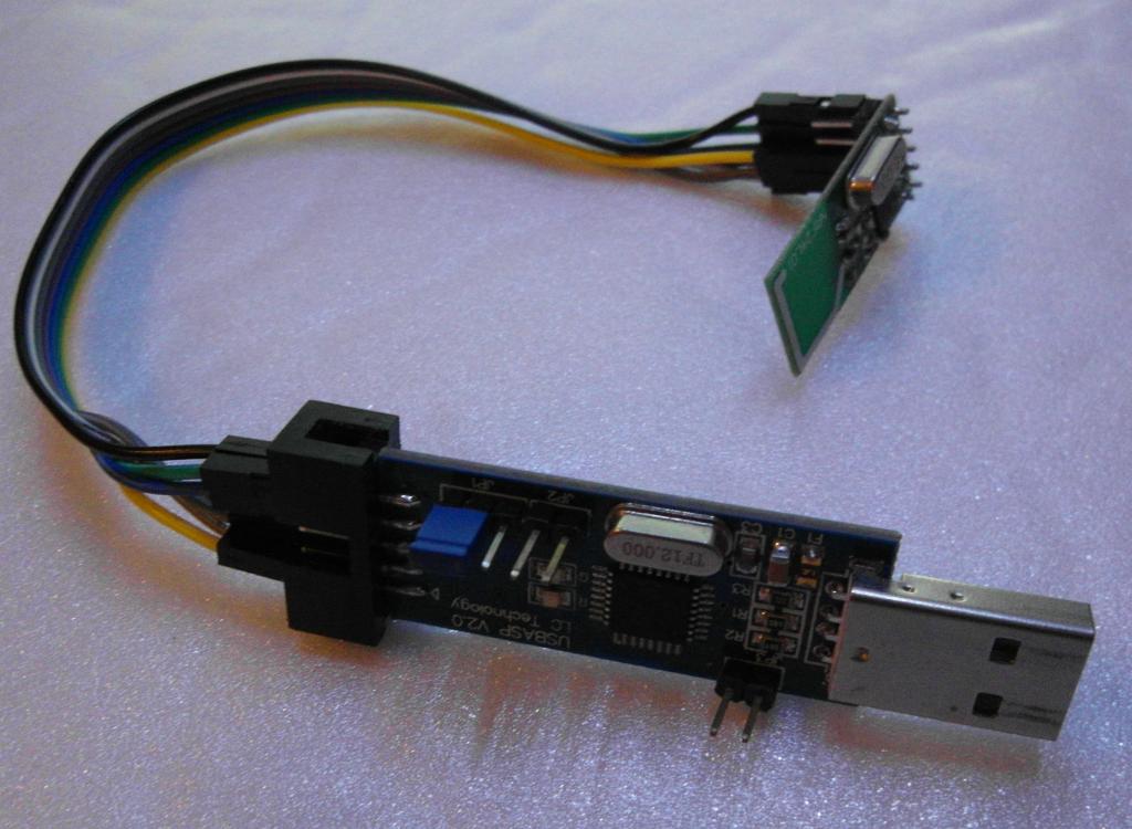
USBasp programmer device
The programmer consists of a small number of parts. The brain of the programmer is the Atmega8 microcontroller, which has only 8 KB of flash memory and 1 KB of RAM (SRAM). It seems to be a weak microcontroller by modern standards, but so much can be done on it. Due to the features of the USB m / c, it works at a frequency 12 MHz Accordingly, when writing your firmware, you must consider this.
USBasp has a 10-pin connector to which 6 pins of the microcontroller are output: PB5 (SCK), PB4 (MISO), PB3 (MOSI, PWM), PB2 (PWM), PD0 (RXD), PD1 (TXD). Power supply 5v or 3.3v which is switched by jumper JP1.
The board has two built-in LEDs on the PC0 and PC1 pins. The PB0, PB1 and PD2 m / k pins are used for USB software, PC2 is connected to jumper JP3. The rest of the microcontroller pins are not soldered.
The device diagram can be found in the archive at the end of the article.
Installing the bootloader on the board
To quickly change the firmware, without third-party programmers can install the bootloader USBaspLoader.Ofitsialnaya project page USBaspLoader
Unfortunately loader takes 2 kb flash memory, but for most applications we have enough remaining 6 kb.
Bootloader installation:
The programming team using Arduino as a programmer:
avrdude -c avrisp -P COM1 -b 19200 -p m8 -U flash:w:boot_m8.hex -U hfuse:w:0xc0:m -U lfuse:w:0x9f:m -U lock:w:0x2f:m
Programming command via another USBasp:
avrdude -c usbasp -p m8 -U flash:w:boot_m8.hex -U hfuse:w:0xc0:m -U lfuse:w:0x9f:m -U lock:w:0x2f:m
After that, you can already upload your firmware without a programmer with the standard command
avrdude -c usbasp -p m8 -U flash:w:имя_файла.hex
In order to “upload” the firmware to a device with USBaspLoader installed, it is necessary to install jumper JP3, which puts the device into programming mode and reset the device by closing the contact closest to the power jumper (JP1) on jumper JP2 to ground.
Using USBasp as a breadboard in Arduino IDE
For firmware in the Arduino IDE (tested on versions 1.0.x), the following text must be entered in the board.txt file:
 atmega8usb.name=ATmega8 USB 12 MHz
 atmega8usb.upload.protocol=arduino
 atmega8usb.upload.maximum_size=6144
 atmega8usb.upload.speed=19200
 atmega8usb.bootloader.low_fuses=0x9f
 atmega8usb.bootloader.high_fuses=0xc0
 atmega8usb.bootloader.path=atmega8
 atmega8usb.bootloader.file=boot_m8.hex
 atmega8usb.bootloader.unlock_bits=0x3F
 atmega8usb.bootloader.lock_bits=0x2F
 atmega8usb.build.mcu=atmega8
 atmega8usb.build.f_cpu=12000000L
 atmega8usb.build.core=arduino
 atmega8usb.build.variant=standard
After that, in the Arduino IDE, you can select the appeared board ATmega8 USB 12 MHz. The firmware is carried out through the menu “download using the programmer”.
Available Arduino number pins: 13 (SCK), 12 (MISO), 11 (MOSI, PWM), 10 PB2 (PWM), 1 (TXD), 0 (RXD). Digital pins 14 and 15 are also available for controlling LEDs on the board.
You can also use the USB interface using the library for the Arduino V-USB, but there are fewer options than in C.
nRF24L01-USB
Allows the exchange of data between nRF24L01 / nRF24LE1 and a computer with an nRF24L01-USB device. Theoretically, up to 22 clients are supported (with a transmission packet of 32 bytes) based on nRF24L01 / nRF24LE1, but so far it has been tested to 3 in practice. The limitation is due to the fact that a buffer is used in the device RAM to receive and send data, and it is known from Atmega8 in total 1kb. The size of the receiving packet can be up to 32 bytes, and the sending size is 4 bytes, this limitation is connected with the way of working with the V-USB library.
The operation of the nRF24L01-USB adapter is based on time sharing, when clients send / receive data at different times. With a large number of customers, the survey time should be longer. For real-time data exchange, the number of clients should be the smallest. So far, the device has some disadvantages, but I think this is solved.
The client utility for managing, reading and sending data works both on Linux and Windows, but so far, unfortunately, compilation is required to configure the received data. For convenience, settings and debugging through the utility, you can change the channel, speed and enable / disable hardware confirmation, work directly with the registers of the radio module.
The device can be used for wireless sensors or control in smart home systems.
By the way, a variant of wireless humidity and temperature sensors based on attiny13 at a frequency of 315 or 433 MHz was previously developed and tested, but this is another topic.
RS232-USB
Based on the USBasp programmer, you can create an RS232-USB adapter device based on the cdc-232 project .
Suitable for programming Arduino boards on which there is no FT232RL chip or other usb-uart converter.
PIO-USB
The 6 pins that are output on the programmer’s connector can be used as regular PIO pins for “pulling” LEDs and reels, as well as reading the logical status of the port. In the archive at the end of the article there is my version of PIO-USB, which also allows you to read the humidity sensor DHT11 / DHT22, as well as broadcast the code to control sockets / chandeliers, if you connect a radio transmitter for 433/315 MHz. A new version is planned, in which the number of connected humidity sensors will increase and bugs will be fixed.
DS18B20-USB
The programmer can be “taught” to work with several DS18B20 temperature sensors. For example, use the USBTemp project .
There are other options for implementing the circuit and firmware of the device, as well as integration with PIO-USB.
Unfortunately, due to the size of the firmware, downloading is not possible via USBaspLoader.
I2C-USB
The device allows you to connect almost any i2c device to your computer. It has been tested on both Linux and Windows XP. The firmware is based on the well-known i2c tiny usb project .
My examples of using the device:
Reading the pressure sensor BMP085.
Management of the chip by the MCP23017 port expander, thereby obtaining almost the same PIO on the computer.
There are a lot of applications: programming EEPROM memory, reading specific specific sensors, controlling the FM receiver.
These, of course, are far from all options for using the programmer in non-standard functioning.
All source codes of third-party projects can be found on their official sites. In the archive at the end of the article there are firmware that are adapted to the conclusions of the USBasp board.
Archive with firmware: usbasp.zip
UPD: Another application of USBasp in the article “Programming nRF24LE1 via Raspberry PI and USBasp” .