How I did a line-interactive UPS (Part 1)
Once there was a task to develop a linear-interactive UPS. This is actually the simplest type of UPS with the “modified sine” output, but additionally having the ability to adjust the output voltage when the input voltage changes. Something like the simplest voltage regulator. The function is idle, but quite useful, allowing not to switch to power from the inverter during short-term failures in the network. Later I will write more about this, but for now I’d like to open this first article with a small cycle. All interested please under the cat.
Part 1
Part 2
Part 3
Let's start with the block diagram of the UPS. It is listed below:
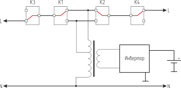
In general, a classic of the genre. The input voltage through relays K3, K1, K2 and K4 passes to the output and feeds the load. In this case, it also enters the main transformer of the UPS, feeds the circuit and charges the battery. The charger is not intentionally allocated to a separate unit, because its function is performed by the inverter, but this will be discussed in more detail next time.
Relays K1 and K2 perform the above autotransformer function. Turning on in different combinations, they operate the UPS transformer in the autotransformer mode and regulate the output voltage.
The above figure shows the state of the relay at the rated voltage of the network.
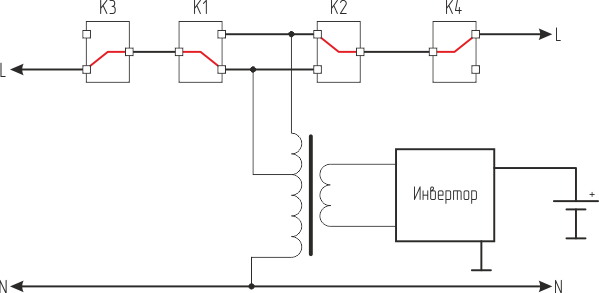
At reduced voltage, the inclusion will be like this:
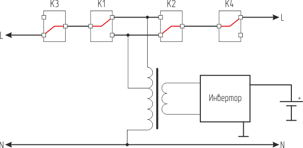
And at elevated levels like this:
As you can see, for now everything is pretty simple. But in order to switch these relays, it is necessary to know the magnitude of the input voltage. Thus, we smoothly proceed to the next part - measurements.
For measurement, we use the following simple scheme (modeled in MicroCap, then fully tested in hardware):

V4, V5 are sources that simulate input and output voltage.
On the opamp assembled simple amplifiers. With R11, R12, a bias voltage of approximately 1.5V is generated.
The resistors are chosen so that at voltages of 270V, the span at the outputs of the opamp is 2.5 V. It is no longer possible to issue a cheap opamp such as the LM358, and we don’t need it.
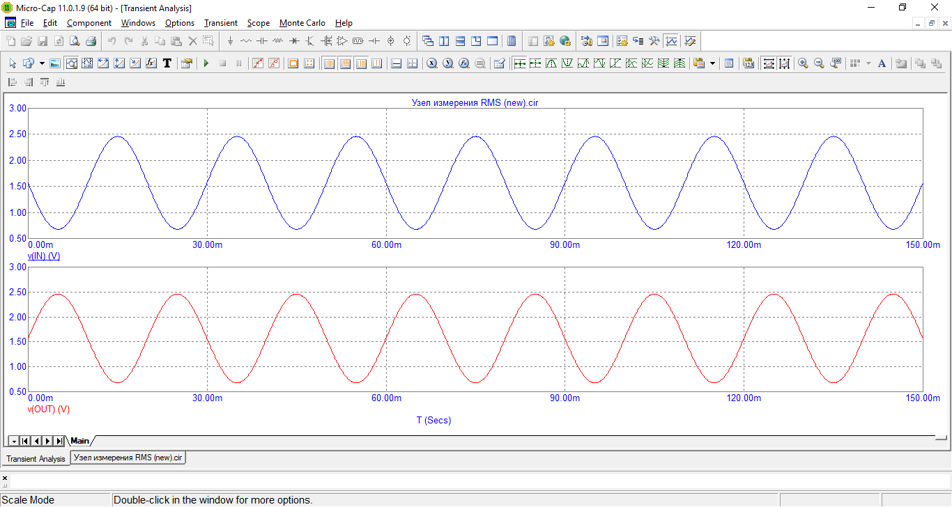
The signal plots are shown below:

There is one trick in the above diagram. This is the use of capacitor C1. Let's look at stress plots, if we exclude it.
This is a situation when there is an input voltage and there is an output:
While there are no differences from the circuit with a capacitor. But let's imagine that V5 is the input voltage. And then suddenly bang, it disappears. We work from the inverter and we have only the output voltage (while we forget about the modified sine wave, now it does not matter). As a result, we get here such epures:

Wow! The operator now gives us a completely different voltage, although in fact nothing has changed! And why? Because there is no AC connection, because no capacitor!
Someone can say, why bother to build this circuit out of parallel-connected capacitor C1 and resistor R13? All to increase the level of protection. After all, we have a measurement node galvanically connected to the input network. R13 reduces current. It is extremely dangerous to plant a phase or zero (it is not known how the user inserts the plug into the outlet) with digital ground. And the presence of a resistor with a capacitor reduces the current to 0.5 mA.
Next, I would like to show the waveforms of the signals after the high-resistance resistors R1 and R4:

And at the output of the opamp:

As you can see, we get a good clean signal suitable for further direct digitization.
In the following articles we will talk about measuring the output current, as well as building an inverter. Very interesting solutions will also be used there!
Part 1
Part 2
Part 3
Introduction
Let's start with the block diagram of the UPS. It is listed below:
In general, a classic of the genre. The input voltage through relays K3, K1, K2 and K4 passes to the output and feeds the load. In this case, it also enters the main transformer of the UPS, feeds the circuit and charges the battery. The charger is not intentionally allocated to a separate unit, because its function is performed by the inverter, but this will be discussed in more detail next time.
Relays K1 and K2 perform the above autotransformer function. Turning on in different combinations, they operate the UPS transformer in the autotransformer mode and regulate the output voltage.
The above figure shows the state of the relay at the rated voltage of the network.
At reduced voltage, the inclusion will be like this:
And at elevated levels like this:
As you can see, for now everything is pretty simple. But in order to switch these relays, it is necessary to know the magnitude of the input voltage. Thus, we smoothly proceed to the next part - measurements.
Measurement of input and output voltage
For measurement, we use the following simple scheme (modeled in MicroCap, then fully tested in hardware):
V4, V5 are sources that simulate input and output voltage.
On the opamp assembled simple amplifiers. With R11, R12, a bias voltage of approximately 1.5V is generated.
The resistors are chosen so that at voltages of 270V, the span at the outputs of the opamp is 2.5 V. It is no longer possible to issue a cheap opamp such as the LM358, and we don’t need it.
The signal plots are shown below:
There is one trick in the above diagram. This is the use of capacitor C1. Let's look at stress plots, if we exclude it.
This is a situation when there is an input voltage and there is an output:
While there are no differences from the circuit with a capacitor. But let's imagine that V5 is the input voltage. And then suddenly bang, it disappears. We work from the inverter and we have only the output voltage (while we forget about the modified sine wave, now it does not matter). As a result, we get here such epures:
Wow! The operator now gives us a completely different voltage, although in fact nothing has changed! And why? Because there is no AC connection, because no capacitor!
Someone can say, why bother to build this circuit out of parallel-connected capacitor C1 and resistor R13? All to increase the level of protection. After all, we have a measurement node galvanically connected to the input network. R13 reduces current. It is extremely dangerous to plant a phase or zero (it is not known how the user inserts the plug into the outlet) with digital ground. And the presence of a resistor with a capacitor reduces the current to 0.5 mA.
Next, I would like to show the waveforms of the signals after the high-resistance resistors R1 and R4:
And at the output of the opamp:
As you can see, we get a good clean signal suitable for further direct digitization.
In the following articles we will talk about measuring the output current, as well as building an inverter. Very interesting solutions will also be used there!