An example of calculating a single-lens in Zemax
- Tutorial
It may happen that someone needs to calculate a simple photo lens for their insidious plans for needs. And since I am an optical engineer by training and a profession (beginner :-), I decided to share a little instruction on calculating a simple single-lens photo lens.

Suppose that our future lens will be in geostationary orbit at an altitude of 35,786 km. The angular field of the lens must be such that the whole Earth falls into it. No more, no less. The receiver will be a photodiode with dimensions of 10mm x 10mm = 100mm2. The diameter of the entrance pupil (in this case, the diameter of the first surface of the first and only optical element) is 20 mm.
To build the optical scheme, we need to determine the required angular field of the system and the focal length.
We know the distance from the surface of the Earth to the entrance pupil of our system and the average diameter of the Earth. From this data, the angular field of the system can be calculated.
The average diameter of the Earth D = 12 742 km (R = 6 371 km)
The distance from the earth's surface to the lens = 35 786 km The
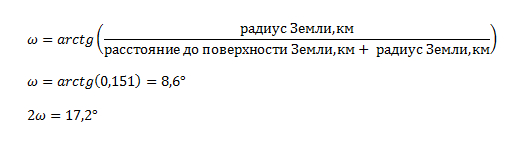
angular field of our system is 17.2 degrees.
Now you need to calculate the required focal length of the system: The
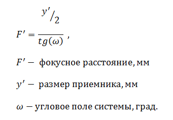
focal length from this formula will be F '= 33.2 mm.
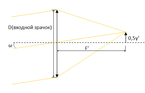
Fig. Schematic diagram
Great! More than half of the work has already been done.
First you need to check the available data.
We know:
- the number of curved surfaces of the system,
- the diameter of the entrance pupil of the system,
- the required focus of the system.
We do not yet know:
- the thickness of the optical component,
- the glass grade of the optical component,
- the wavelength at which the optical system will work.
You can select this data yourself. But imagine that we are working in some advanced enterprise that is exploring space :-)
I was taught at the institute that the minimum thickness of the optical component along the axis should be at least 10% of the diameter. If we calculate the optical component with a small negative focus (most likely it is a biconcave lens), then the axial thickness of 10% of the diameter is quite enough. In our case, we have a collecting lens forming an actual image (an imaginary image in the scattering lens) with a positive focus. Accordingly, it is necessary to choose the thickness of the lens, taking into account the arrows of the deflection of the surfaces, which will increase the thickness of the component along the axis. For a first approximation, we take 20% of the diameter. In our case, the thickness of the component for calculations will be:
Lens thickness = 20mm x 20% = 4mm
Suppose that a radiation resistance specialist recommended the use of radiation-resistant glass. And the thermal specialist recommended using a glass material with the lowest rate of thermal expansion, since the frame for the lens will be made of titanium or superinvar. In general, they have not yet decided.
Having received recommendations, it was decided that quartz glass of the KU-1 brand is perfect. No sooner said than done!
It seems to be eating almost all the data. Karamba! But what about the spectral range of the system? We take the initiative and go to the developers ourselves and get the necessary information. After that we wait a couple of days and do other useful things. On the third day, the developer comes and says that they decided to change the main wavelength for the lens. No sooner said than done! Operating wavelength = 0.644 μm. Now we can continue our optical calculation.
Zemax software makes life easier for optical system designers. This does not mean that the software itself will design a cool optical system for you. But when designing optical systems when it is necessary to analyze a sufficient number of options, Zemax helps to significantly reduce development time. I believe that the program for counters is indispensable. Of course, with one condition that you have purchased the original license ;-)
Now I will not go into details of the description of all the delights of the program, but I will immediately show it in action.
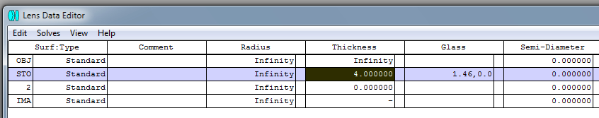
When downloading a program, first of all, you need to familiarize yourself with the Lens Data Editor
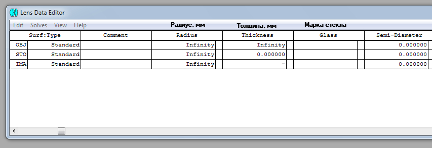
window : This window contains information about the current optical system. The data set is similar to the optical release format, which I personally met at the institute :-)
From the available data at the moment, here we can indicate so far only the number of surfaces for ray tracing, thickness and grade of glass. As a glass brand, we will choose the data representation in the form of a model in which it is necessary to set the refractive index for the selected wavelength for our glass. Since the brand of the selected KU-1 glass is from Russian GOST, the data must be searched for in it (in our case GOST 15130-86 “Optical quartz glass”).
The refractive index for KU-1 glass for a wavelength of 0.644 μm is 1.4567. It is worth noting that this is at a temperature of +20 degrees Celsius. And we have just on board heating up to +20 degrees :-)

Total, at the moment we have:
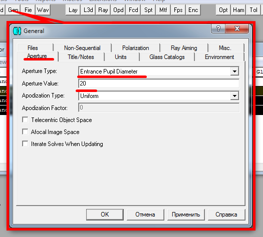
In the General window on the Aperture tabindicate the entrance pupil diameter 20mm:
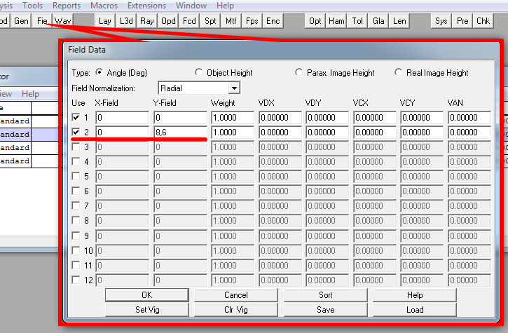
indicate the angular field of the system:
When calculating the system, we will use Optimization , which is built into Zemax.
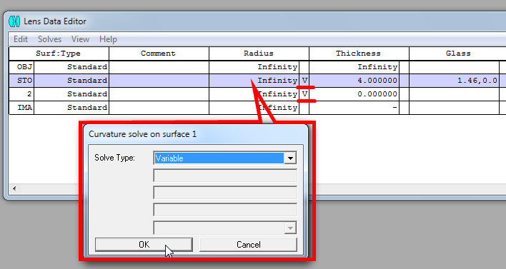
Firstly, we indicate the parameters that we can change during optimization. In our case, these are the radii of curvature of the lens surfaces:
Secondly, it is necessary to form the estimated function of the current system (Default Merit Function).

We form an evaluation function based on RMS. Here, this parameter shows the standard deviation of the wavefront rays during ray tracing.
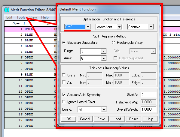
During optimization, we will indicate the only parameter we will strive for - the required focal length. To do this, add the EFFL parameter and specify the following settings:

Now that all the parameters are set, you can use the optimization function.
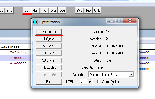
In this window, you can manually control the number of iterations when selecting the best option. Or you can use automatic calculation to find the best option.
We optimize. Click Exit .
Now you can see what happened.

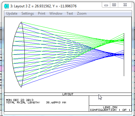
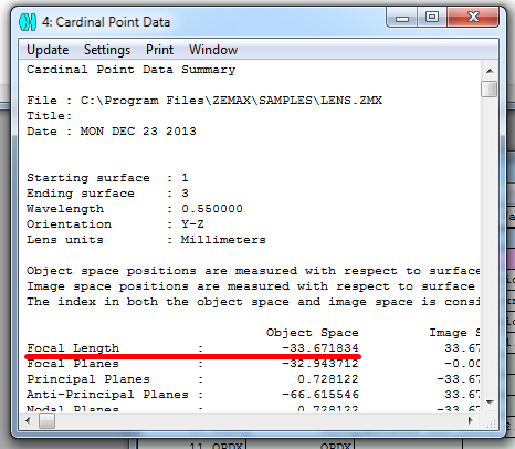
It seems to be nice :-)
But the final focus of the system is 33.67 mm, which is slightly different from the target - 33.2 mm.
The higher the Weight value in the EFFL parameter, the higher the priority of this parameter in the calculation.
With the parameter Weight = 100,000, my optimized focus turned out to be 33.21 mm. I do not give the sequence, since it is similar to the above.
The requirements are met. Hurrah! :-)
PS I have not had time to master the entire functionality of the program. Yes, and optical systems, I did not particularly calculate a lot for the whole time, so excuse me if something is wrong. Comments and comments are welcome :-)
PPS This is my first post, so I did not know which topic is better to post. If not right, then tell me where to transfer. Thanks.
Statement of the problem and initial data
Suppose that our future lens will be in geostationary orbit at an altitude of 35,786 km. The angular field of the lens must be such that the whole Earth falls into it. No more, no less. The receiver will be a photodiode with dimensions of 10mm x 10mm = 100mm2. The diameter of the entrance pupil (in this case, the diameter of the first surface of the first and only optical element) is 20 mm.
Optical design
To build the optical scheme, we need to determine the required angular field of the system and the focal length.
Angular field of the system
We know the distance from the surface of the Earth to the entrance pupil of our system and the average diameter of the Earth. From this data, the angular field of the system can be calculated.
The average diameter of the Earth D = 12 742 km (R = 6 371 km)
The distance from the earth's surface to the lens = 35 786 km The
angular field of our system is 17.2 degrees.
Now you need to calculate the required focal length of the system: The
focal length from this formula will be F '= 33.2 mm.
Fig. Schematic diagram
Great! More than half of the work has already been done.
Collection of additional parameters for calculation
First you need to check the available data.
We know:
- the number of curved surfaces of the system,
- the diameter of the entrance pupil of the system,
- the required focus of the system.
We do not yet know:
- the thickness of the optical component,
- the glass grade of the optical component,
- the wavelength at which the optical system will work.
You can select this data yourself. But imagine that we are working in some advanced enterprise that is exploring space :-)
Optical component thickness
I was taught at the institute that the minimum thickness of the optical component along the axis should be at least 10% of the diameter. If we calculate the optical component with a small negative focus (most likely it is a biconcave lens), then the axial thickness of 10% of the diameter is quite enough. In our case, we have a collecting lens forming an actual image (an imaginary image in the scattering lens) with a positive focus. Accordingly, it is necessary to choose the thickness of the lens, taking into account the arrows of the deflection of the surfaces, which will increase the thickness of the component along the axis. For a first approximation, we take 20% of the diameter. In our case, the thickness of the component for calculations will be:
Lens thickness = 20mm x 20% = 4mm
Glass brand selection
Suppose that a radiation resistance specialist recommended the use of radiation-resistant glass. And the thermal specialist recommended using a glass material with the lowest rate of thermal expansion, since the frame for the lens will be made of titanium or superinvar. In general, they have not yet decided.
Having received recommendations, it was decided that quartz glass of the KU-1 brand is perfect. No sooner said than done!
Wavelength selection
It seems to be eating almost all the data. Karamba! But what about the spectral range of the system? We take the initiative and go to the developers ourselves and get the necessary information. After that we wait a couple of days and do other useful things. On the third day, the developer comes and says that they decided to change the main wavelength for the lens. No sooner said than done! Operating wavelength = 0.644 μm. Now we can continue our optical calculation.
System Calculation Using Zemax
Zemax software makes life easier for optical system designers. This does not mean that the software itself will design a cool optical system for you. But when designing optical systems when it is necessary to analyze a sufficient number of options, Zemax helps to significantly reduce development time. I believe that the program for counters is indispensable. Of course, with one condition that you have purchased the original license ;-)
Now I will not go into details of the description of all the delights of the program, but I will immediately show it in action.
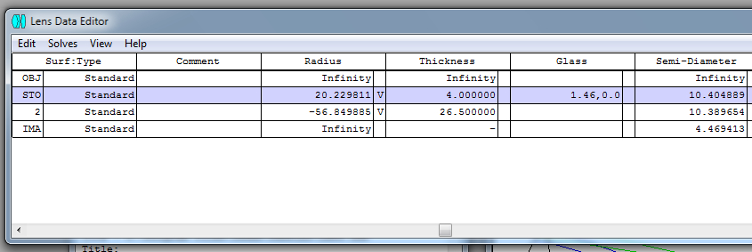
When downloading a program, first of all, you need to familiarize yourself with the Lens Data Editor
window : This window contains information about the current optical system. The data set is similar to the optical release format, which I personally met at the institute :-)
From the available data at the moment, here we can indicate so far only the number of surfaces for ray tracing, thickness and grade of glass. As a glass brand, we will choose the data representation in the form of a model in which it is necessary to set the refractive index for the selected wavelength for our glass. Since the brand of the selected KU-1 glass is from Russian GOST, the data must be searched for in it (in our case GOST 15130-86 “Optical quartz glass”).
The refractive index for KU-1 glass for a wavelength of 0.644 μm is 1.4567. It is worth noting that this is at a temperature of +20 degrees Celsius. And we have just on board heating up to +20 degrees :-)
Total, at the moment we have:
In the General window on the Aperture tabindicate the entrance pupil diameter 20mm:
indicate the angular field of the system:
Setting up automatic optimization
When calculating the system, we will use Optimization , which is built into Zemax.
Firstly, we indicate the parameters that we can change during optimization. In our case, these are the radii of curvature of the lens surfaces:
Secondly, it is necessary to form the estimated function of the current system (Default Merit Function).
We form an evaluation function based on RMS. Here, this parameter shows the standard deviation of the wavefront rays during ray tracing.
During optimization, we will indicate the only parameter we will strive for - the required focal length. To do this, add the EFFL parameter and specify the following settings:
Now that all the parameters are set, you can use the optimization function.
In this window, you can manually control the number of iterations when selecting the best option. Or you can use automatic calculation to find the best option.
We optimize. Click Exit .
Now you can see what happened.
It seems to be nice :-)
But the final focus of the system is 33.67 mm, which is slightly different from the target - 33.2 mm.
How to get the required focus?
The higher the Weight value in the EFFL parameter, the higher the priority of this parameter in the calculation.
With the parameter Weight = 100,000, my optimized focus turned out to be 33.21 mm. I do not give the sequence, since it is similar to the above.
Total
The requirements are met. Hurrah! :-)
PS I have not had time to master the entire functionality of the program. Yes, and optical systems, I did not particularly calculate a lot for the whole time, so excuse me if something is wrong. Comments and comments are welcome :-)
PPS This is my first post, so I did not know which topic is better to post. If not right, then tell me where to transfer. Thanks.