Flow effect in CorelDRAW
- Tutorial
The overflow effect creates a series of objects between two control objects. Control objects can be closed and open curves or a group of objects. If the control objects coincide in shape and color, then the effect creates a series of identical copies, otherwise a gradual transformation of one object to another takes place. Using this interesting property of the tool, you can create volumetric effects or objects of complex shape. In this article, we will consider the technology for constructing the overflow effect and give some examples of its application.
To form the overflow, you must first create two objects that may differ from each other in shape and color. After selecting the Blend tool , draw a line from the center of one shape to the center of another. The tool will automatically create a series of objects between these source shapes. In fig. Figure 1 shows an example of constructing a flow between two figures: a star and a circle. Blue arrows indicate control object markers, red indicate a flow path indicator, green indicates an object’s acceleration marker, and yellow indicates a color acceleration marker. The first and last overflow objects are called controllers, the rest located between them form an overflow group.

Fig. 1. Interactive markers that control the flow effect
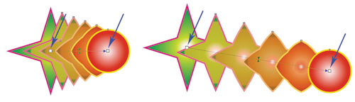
Fig. 2. Changing the position of control objects
Using the following markers, you can configure the effect:

Fig. 3. Change in the acceleration of the object (a) and color (b)
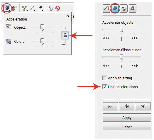
Fig. 4. Linking and disconnecting accelerations: a - on the property panel, b - on the Blend panel
By default, when the overflow effect is assigned, both markers are in the center of the overflow path (see Figure 1) and are interconnected, that is, changing the acceleration of the object and color happens at the same time. To break the connection, click the button with the lock on the tool properties panel or uncheck the Link accelerations checkbox on the Blend docking panel - Fig. 4.
Other settings can be made using the buttons on the tool properties panel or on the Blend panel . Parameters of the Blend Steps (Steps overflow) andBlend Space ( Blend Interval) sets the number of overflow steps and the interval between steps; by default, 20 objects of the group are created (Fig. 5).
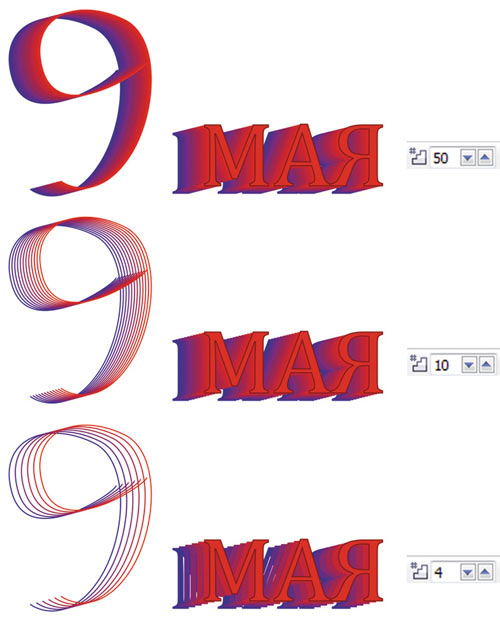
Fig. 5. Examples of using the Blend Steps parameter: а - the value is 50; b - 10; c - 4
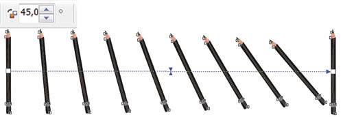
Fig. 6. Example for Blend Direction
Parameter Blend Direction (Direction overflow) to create a flow of a turn, in Fig. 6 the last object of the overflow group is rotated 45 °.
If the direction of flow is not set to 0 °, then the Loop Blend parameter becomes available(Flowing with repetition). Pressing the Loop Blend button performs a rotation effect while simultaneously moving the objects of the flow group relative to the path. In fig. Figure 7 shows two effects with the same settings: the rotation angle is set to –180 ° and the Loop Blend button is pressed . But in the upper figure, both control objects are left unchanged, and in the lower one, one control overflow object (indicated by a red arrow) is reflected horizontally.
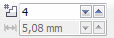
Fig. 7. Examples sharing parameters Blend Direction and Loop Blend
The following three buttons in the toolbar - Direct Blend (Direct overflow), Clockwise Blend (Reallocation clockwise) andCounterclockwise Blend - Responsible for the color transition. The first button, pressed by default, creates the effect of a smooth color transition from one color to another. The remaining buttons allow you to set the color transition through the visible spectrum (Fig. 8).
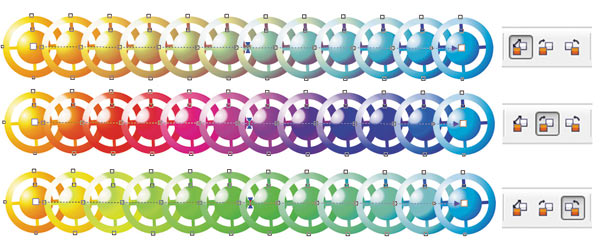
Fig. 8. Variants of color transition
When adjusting the effect of blending, what objects are highlighted is of great importance. If you click the Pick tool(Selection) for one of the control objects, then it will be selected. With the selected control object, you can perform various actions, as with a normal vector object: scale, rotate, move, edit its nodes, reflect horizontally or vertically, etc. After editing this object, the overflow group objects are automatically converted. So, in fig. 9, when the upper control object was rotated, all objects of the overflow group automatically changed.
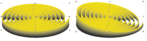
Fig. 9. Editing a control object
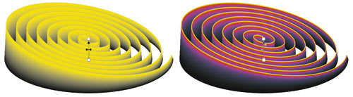
Fig. 10. Editing flow group objects
If using Pick tool(Selection) click on one of the objects of the overflow group, then the whole group will be selected. In this case, we get access to edit the overflow parameters using the buttons on the properties panel of the Blend tool , but first select this tool again (Fig. 10).
Each overflow group object can be assigned as a child object and edited as a control object, which, in turn, will affect the appearance of the overflow effect. Consider an example.
Create a simple flow between the two shapes, then double-click on the group object, which will be the disconnect point. In fig. 11a there are two such objects (they are indicated by green arrows). Then we will shift markers of child objects. In fig. 11b relocated child and one control objects. Note that any child object can be edited as a manager, while the objects of the overflow group will be automatically redrawn (Fig. 11c).

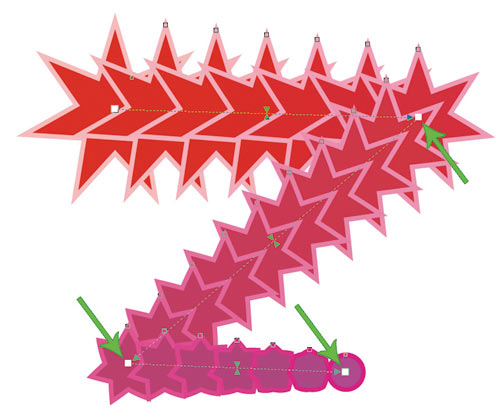
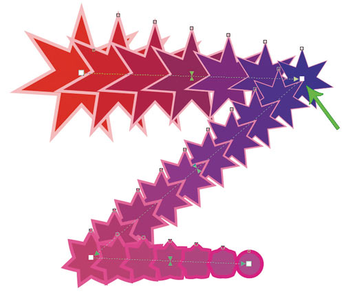
Fig. 11. Overflow with two disconnection points (a); change of position of subsidiaries and managing objects (b); result of editing a child object (c)
To disconnect, you can also use the Split button on the docking Blend panel or on the toolbar. As a result of pressing this button, the mouse pointer is displayed in the form of a curved arrow, which should be clicked on the desired object from the overflow group (Fig. 12).
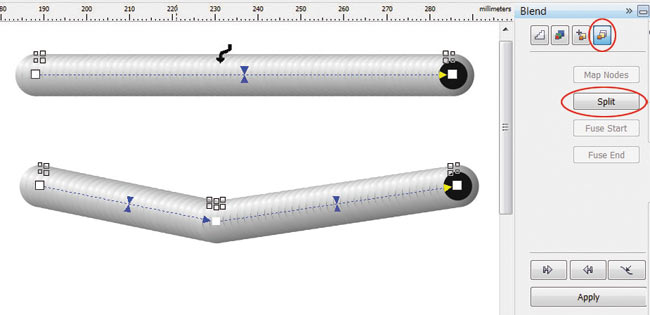
Fig. 12. Using the Split button to disconnect the flow
To connect the flow, double-click on the marker of the child.
Compound overflow is used between three or more objects. You must first prepare control objects, and then sequentially connect them in the mode of the Blend tool . As a result of this, we will get several separate, interconnected flow effects, each of which has its own control objects. Consider an example of drawing a dumbbell.
Let's create some ovals - future control objects, fill them with a fountain fill (Fig. 13a).
Then select the Blend Tool(Overflow) and sequentially connect the ovals from left to right (Fig. 13b). As a result, we get the image shown in Fig. 13th century And at the end of the effect, create a copy of the last control object, flip it horizontally and assign the thinnest outline (Fig. 13d).
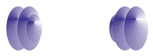

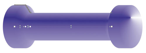
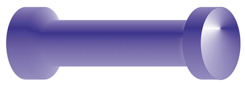
Fig. 13. Source objects for composite overflow (a); the sequence of the connection of the ovals (b); the result of applying the overflow effect (c); dumbbell total image (g)
The overflow effect can be located not only along a straight path or a broken line - you can also use a closed or open curve as a path. This overflow is formed in two stages: first, a simple overflow between two figures is built, and then it is attached to a pre-built curve. Consider an example of drawing a caterpillar.
Create a regular flow between two shapes. We draw a curve along which we are going to arrange the ovals. Then, on the tool’s properties panel or in the docking Blend panel, click the Path Properties button and select the New Path command . As a result, the pointer changes to a curved arrow, which should be clicked on the curve (Fig. 14a).

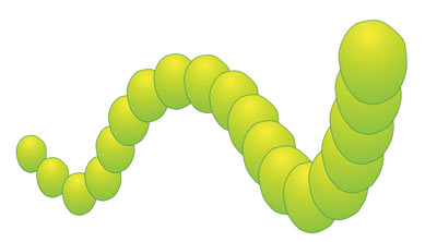
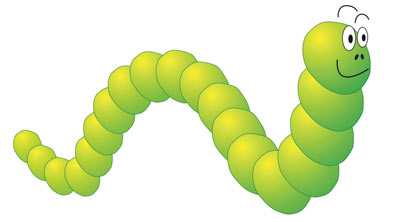
Fig. 14. The process of assigning a new path for easy flow (a); binding flow to an open curve using the New Path command (b); final image of the caterpillar (c)
If the figures are not located along the entire length of the path, simply drag the control objects to the ends of the curve. As a result of our manipulations, the figures should be strung along the entire curve (Fig. 14b).
All usual actions are applicable to overflow along a path: rotation of control objects and group objects, change of acceleration of color and object, repainting of overflow, etc. Having a little edited the obtained effect and having finished the face, we get the finished image of the caterpillar (Fig. 14c).
Note that the overflow can also be automatically placed along the entire path. To do this, check the box.Blend along full path (on the tool properties panel or on the docking Blend panel ) - Fig. 15.
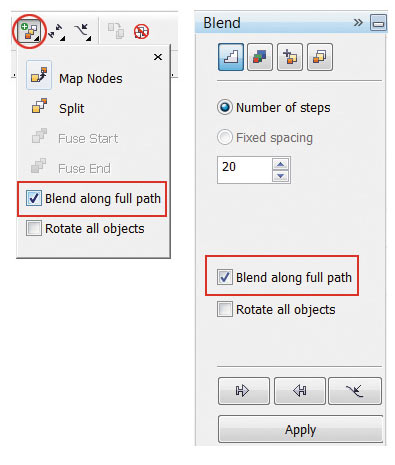
Fig. 15. Automatic placement of overflow along the entire path: a - in the toolbar of the Blend tool; b - in the Blend panel
In addition to rotating objects at an arbitrary angle, it is possible to automatically align the objects of the overflow group according to the orientation of the path itself. To do this, use the second checkbox Rotate all objects on the property panel or in the docked Blend panel (see Figure 15).
In fig. 16a shows a group of ovals strung on an open curve.
Let's make them look like beads. To do this, it is necessary to align each oval along the path so that the thread “pierces” each bead along the long axis of the ellipse. Let us turn each of the control objects in the required manner, but as a result of this, the size of the ovals located in the center of the curve slightly decreases (Fig. 16b). To fix this, check the Rotate all objects box.(Rotate all objects) - Fig. 16th century Now we will reduce the number of objects in the overflow group and move the “thread” to the background (Fig. 16d).
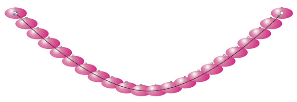
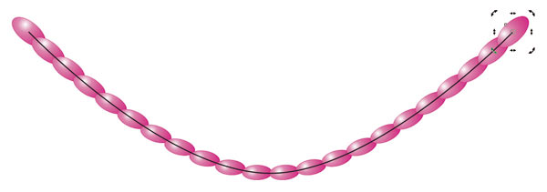
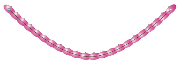
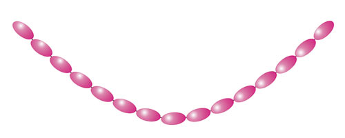
Fig. 16. The result of placing a simple overflow along curve (a); the result of rotation of both control objects (b); the result of setting the checkbox Rotate all objects (in); final image beads (g)
The path on which the flow objects are already strung can be edited as a normal curve. But first you need to select it - for this, the Show Path command is used on the property panel or on the docking Blend panel (Figure). 17.
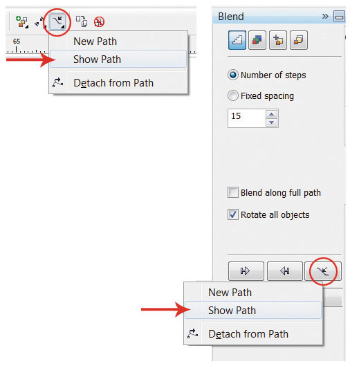
Fig. 17. Selecting a path using the Show Path command: a - in the properties panel of the Blend tool b - in the Blend panel
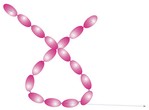
Fig. 18. Example of editing the flow path
After selecting with the path, you can perform various actions, for example, edit nodes and guides of the curve (Fig. 18).
If you want to make the path invisible in the final effect, cancel the outline color for it. And when you need to edit it, run the Show Path command (Show way).
To cancel the flow effect, click the last button on the tool properties panel or choose Effects → Clear Blend .
As you can see, the possibilities of the overflow effect make it a really very useful and indispensable tool for the designer when working with objects in the CorelDRAW editor.
Based on COREL Magazine
Simple overflow
To form the overflow, you must first create two objects that may differ from each other in shape and color. After selecting the Blend tool , draw a line from the center of one shape to the center of another. The tool will automatically create a series of objects between these source shapes. In fig. Figure 1 shows an example of constructing a flow between two figures: a star and a circle. Blue arrows indicate control object markers, red indicate a flow path indicator, green indicates an object’s acceleration marker, and yellow indicates a color acceleration marker. The first and last overflow objects are called controllers, the rest located between them form an overflow group.
Fig. 1. Interactive markers that control the flow effect
Fig. 2. Changing the position of control objects
Using the following markers, you can configure the effect:
- control object markers are used to change the position of the first and last objects in the overflow, moreover, the distance between the objects of the group changes automatically (Fig. 2);
- acceleration markers are used to change the color and distance between group objects. For example, if the object acceleration marker (upper triangle) is shifted to the right, the group of objects will shift to the second control object (circle), and when the color acceleration marker is shifted to the right (lower triangle), the green color of the group objects will prevail over red (Fig. 3).
Fig. 3. Change in the acceleration of the object (a) and color (b)
Fig. 4. Linking and disconnecting accelerations: a - on the property panel, b - on the Blend panel
By default, when the overflow effect is assigned, both markers are in the center of the overflow path (see Figure 1) and are interconnected, that is, changing the acceleration of the object and color happens at the same time. To break the connection, click the button with the lock on the tool properties panel or uncheck the Link accelerations checkbox on the Blend docking panel - Fig. 4.
Other settings can be made using the buttons on the tool properties panel or on the Blend panel . Parameters of the Blend Steps (Steps overflow) andBlend Space ( Blend Interval) sets the number of overflow steps and the interval between steps; by default, 20 objects of the group are created (Fig. 5).
Fig. 5. Examples of using the Blend Steps parameter: а - the value is 50; b - 10; c - 4
Fig. 6. Example for Blend Direction
Parameter Blend Direction (Direction overflow) to create a flow of a turn, in Fig. 6 the last object of the overflow group is rotated 45 °.
If the direction of flow is not set to 0 °, then the Loop Blend parameter becomes available(Flowing with repetition). Pressing the Loop Blend button performs a rotation effect while simultaneously moving the objects of the flow group relative to the path. In fig. Figure 7 shows two effects with the same settings: the rotation angle is set to –180 ° and the Loop Blend button is pressed . But in the upper figure, both control objects are left unchanged, and in the lower one, one control overflow object (indicated by a red arrow) is reflected horizontally.
Fig. 7. Examples sharing parameters Blend Direction and Loop Blend
The following three buttons in the toolbar - Direct Blend (Direct overflow), Clockwise Blend (Reallocation clockwise) andCounterclockwise Blend - Responsible for the color transition. The first button, pressed by default, creates the effect of a smooth color transition from one color to another. The remaining buttons allow you to set the color transition through the visible spectrum (Fig. 8).
Fig. 8. Variants of color transition
When adjusting the effect of blending, what objects are highlighted is of great importance. If you click the Pick tool(Selection) for one of the control objects, then it will be selected. With the selected control object, you can perform various actions, as with a normal vector object: scale, rotate, move, edit its nodes, reflect horizontally or vertically, etc. After editing this object, the overflow group objects are automatically converted. So, in fig. 9, when the upper control object was rotated, all objects of the overflow group automatically changed.
Fig. 9. Editing a control object
Fig. 10. Editing flow group objects
If using Pick tool(Selection) click on one of the objects of the overflow group, then the whole group will be selected. In this case, we get access to edit the overflow parameters using the buttons on the properties panel of the Blend tool , but first select this tool again (Fig. 10).
Multipoint Flow
Each overflow group object can be assigned as a child object and edited as a control object, which, in turn, will affect the appearance of the overflow effect. Consider an example.
Create a simple flow between the two shapes, then double-click on the group object, which will be the disconnect point. In fig. 11a there are two such objects (they are indicated by green arrows). Then we will shift markers of child objects. In fig. 11b relocated child and one control objects. Note that any child object can be edited as a manager, while the objects of the overflow group will be automatically redrawn (Fig. 11c).
Fig. 11. Overflow with two disconnection points (a); change of position of subsidiaries and managing objects (b); result of editing a child object (c)
To disconnect, you can also use the Split button on the docking Blend panel or on the toolbar. As a result of pressing this button, the mouse pointer is displayed in the form of a curved arrow, which should be clicked on the desired object from the overflow group (Fig. 12).
Fig. 12. Using the Split button to disconnect the flow
To connect the flow, double-click on the marker of the child.
Composite overflow
Compound overflow is used between three or more objects. You must first prepare control objects, and then sequentially connect them in the mode of the Blend tool . As a result of this, we will get several separate, interconnected flow effects, each of which has its own control objects. Consider an example of drawing a dumbbell.
Let's create some ovals - future control objects, fill them with a fountain fill (Fig. 13a).
Then select the Blend Tool(Overflow) and sequentially connect the ovals from left to right (Fig. 13b). As a result, we get the image shown in Fig. 13th century And at the end of the effect, create a copy of the last control object, flip it horizontally and assign the thinnest outline (Fig. 13d).
Fig. 13. Source objects for composite overflow (a); the sequence of the connection of the ovals (b); the result of applying the overflow effect (c); dumbbell total image (g)
Flowing along a path
The overflow effect can be located not only along a straight path or a broken line - you can also use a closed or open curve as a path. This overflow is formed in two stages: first, a simple overflow between two figures is built, and then it is attached to a pre-built curve. Consider an example of drawing a caterpillar.
Create a regular flow between two shapes. We draw a curve along which we are going to arrange the ovals. Then, on the tool’s properties panel or in the docking Blend panel, click the Path Properties button and select the New Path command . As a result, the pointer changes to a curved arrow, which should be clicked on the curve (Fig. 14a).
Fig. 14. The process of assigning a new path for easy flow (a); binding flow to an open curve using the New Path command (b); final image of the caterpillar (c)
If the figures are not located along the entire length of the path, simply drag the control objects to the ends of the curve. As a result of our manipulations, the figures should be strung along the entire curve (Fig. 14b).
All usual actions are applicable to overflow along a path: rotation of control objects and group objects, change of acceleration of color and object, repainting of overflow, etc. Having a little edited the obtained effect and having finished the face, we get the finished image of the caterpillar (Fig. 14c).
Note that the overflow can also be automatically placed along the entire path. To do this, check the box.Blend along full path (on the tool properties panel or on the docking Blend panel ) - Fig. 15.
Fig. 15. Automatic placement of overflow along the entire path: a - in the toolbar of the Blend tool; b - in the Blend panel
Rotation of flowing objects along a path
In addition to rotating objects at an arbitrary angle, it is possible to automatically align the objects of the overflow group according to the orientation of the path itself. To do this, use the second checkbox Rotate all objects on the property panel or in the docked Blend panel (see Figure 15).
In fig. 16a shows a group of ovals strung on an open curve.
Let's make them look like beads. To do this, it is necessary to align each oval along the path so that the thread “pierces” each bead along the long axis of the ellipse. Let us turn each of the control objects in the required manner, but as a result of this, the size of the ovals located in the center of the curve slightly decreases (Fig. 16b). To fix this, check the Rotate all objects box.(Rotate all objects) - Fig. 16th century Now we will reduce the number of objects in the overflow group and move the “thread” to the background (Fig. 16d).
Fig. 16. The result of placing a simple overflow along curve (a); the result of rotation of both control objects (b); the result of setting the checkbox Rotate all objects (in); final image beads (g)
Overflow Path Editing
The path on which the flow objects are already strung can be edited as a normal curve. But first you need to select it - for this, the Show Path command is used on the property panel or on the docking Blend panel (Figure). 17.
Fig. 17. Selecting a path using the Show Path command: a - in the properties panel of the Blend tool b - in the Blend panel
Fig. 18. Example of editing the flow path
After selecting with the path, you can perform various actions, for example, edit nodes and guides of the curve (Fig. 18).
If you want to make the path invisible in the final effect, cancel the outline color for it. And when you need to edit it, run the Show Path command (Show way).
Cancel overflow
To cancel the flow effect, click the last button on the tool properties panel or choose Effects → Clear Blend .
As you can see, the possibilities of the overflow effect make it a really very useful and indispensable tool for the designer when working with objects in the CorelDRAW editor.
Based on COREL Magazine