Working with tables in MultiCAD.NET. Part 2. Creating and Editing
In a previous article, we introduced you to an example of using the MultiCAD.NET API table functionality to automatically generate a report on selected objects. We intentionally violate the chronology and today's publication will begin by creating and formatting a simple table. Consider filling the table with data in text and numerical format, as well as the use of formulas. Then we move on to adding blocks and subtable as the contents of the cells and end the article with a description of the use of properties of drawing objects as dynamically changing table data.
Creating and formatting tables
In the MultiCAD.NET API, tables are represented by a class
McTablefrom a namespace Multicad.Symbols.Tables. The following code snippet creates an empty table, and then adds 2 rows and 3 columns to it, starting at position zero:McTable Table1 = new McTable();
int rowCount = 4; int colCount = 5;
Table1.Rows.AddRange(0, rowCount + 1);
Table1.Columns.AddRange(0, colCount);
In the same way, any range of rows and columns can be added to the specified positions.
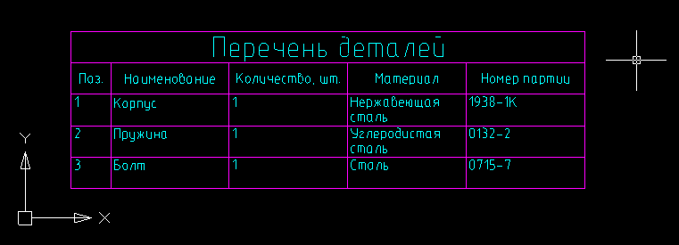
Add the contents for the newly created table and define the format of the cells. For example, the table will store data on the list of parts: serial number in the table, name, batch number, material and quantity. For cells containing the number of units, we will determine the number format, the remaining cells will contain text.
// Sets color and text height that will be used for all table cells by default:
Table1.DefaultCell.TextHeight = 2.5;
Table1.DefaultCell.TextColor = System.Drawing.Color.Aqua;
// The first row is the title, let's merge all its cells and set text alignment and height
System.Drawing.Rectangle rect = new System.Drawing.Rectangle(0, 0, colCount - 1, 0);
Table1.Merge(rect);
Table1[0, 0].HorizontalTextAlign = HorizTextAlign.Center;
Table1[0, 0].VerticalTextAlign = VertTextAlign.Center;
Table1[0, 0].TextHeight = 5;
// Fill up the table
foreach (var cell in Table1.Rows[2].Cells)
{
  cell.VerticalTextAlign = VertTextAlign.Center;
  cell.HorizontalTextAlign = HorizTextAlign.Center;
}
Table1.Columns[0].Width = 10;
Table1[0, 0].Value = "Перечень деталей";
Table1[1, 0].Value = "Поз.";
Table1[1, 1].Value = "Наименование";
Table1[1, 2].Value = "Количество, шт.";
Table1[1, 3].Value = "Материал";
Table1[1, 4].Value = "Номер партии";
Table1[2, 0].Value = "1.";
Table1[2, 1].Value = "Корпус";
Table1[2, 2].Type = CellFormatEnum.Number;
Table1[2, 2].Value = "1";
Table1[2, 3].Value = "Нержавеющая сталь";
Table1[2, 4].Value = "1938-1К";
Table1[3, 0].Value = "2.";
Table1[3, 1].Value = "Пружина";
Table1[3, 2].Type = CellFormatEnum.Number;
Table1[3, 2].Value = "1";
Table1[3, 3].Value = "Углеродистая сталь";
Table1[3, 4].Value = "0132-2";
Table1[4, 0].Value = "3.";
Table1[4, 1].Value = "Болт";
Table1[4, 2].Type = CellFormatEnum.Number;
Table1[4, 2].Value = "1";
Table1[4, 3].Value = "Сталь";
Table1[4, 4].Value = "0715-7";
One of the distinguishing features of tables in MultiCAD.NET is the ability to specify the placement of text in a cell if, when filling out the table, the width or height of the text is larger than the cell size. Using the property,
HorzFitsyou can set the following horizontal inscription modes:HorizontalFitsEnum.None- do not enter text, the text may overlap adjacent cells,HorizontalFitsEnum.Shrink- compress text horizontally (default mode),HorizontalFitsEnum.Wrap- carry over words.
The property
VertFitssets the vertical text fit:VerticalFitsEnum.None- do not enter text, the text may overlap adjacent cells,VerticalFitsEnum.Shrink- reduce the font height (default mode),VerticalFitsEnum.Expand- increase the height of the line,VerticalFitsEnum.AddRows- add pseudo-lines for each line of text.
Of course, after the table is formed, you can edit its structure. For example, add, delete, or copy rows and columns. Add one more record about the Bolt part to the list, move the Quantity column to the last position and delete the column with the serial numbers of the parts:
Table1.Rows.CopyRange(4, 5, 1, true);
Table1.Columns.Move(2,5);
Table1.Columns.Delete(0);

Then we add the ability to take into account the total number of parts in the table using the built-in tabular formula "Sum":
Table1.Rows.AddRange(Table1.Rows.Count, 1);
System.Drawing.Rectangle rect2 = new System.Drawing.Rectangle(0, Table1.Rows.Count - 1, Table1.Columns.Count - 2, 0);
Table1.Merge(rect2);
Table1[Table1.Rows.Count - 1, 0].TextHeight = 5;
Table1[Table1.Rows.Count - 1, 0].Value = "Итого:";
String SummStartCell = Table1[2, Table1.Columns.Count - 1].AddressOfCell();
String SummEndCell = Table1[Table1.Rows.Count - 2, Table1.Columns.Count - 1].AddressOfCell();
Table1[Table1.Rows.Count - 1, Table1.Columns.Count - 1].ValueFormula = "=summ(" + SummStartCell + ":" + SummEndCell + ")";
As a result, our table will look like this:

To summarize data from a range of cells, a string representation of the formula was added to the final cell. In the table editor, the contents of this cell will look like this:

The table editor itself can be called up by double-clicking on the table in the drawing or programmatically - by calling the method
OnEdit()on the table object. Please note that in the example, for the contents of cells with the number of parts, a numerical format was previously set. By default, a format is used
Autothat allows you to determine the data type automatically.Adding a table to a drawing
As a normal primitive, a table can be added to a drawing using one of two methods:
Table.DbEntity.AddToCurrentDocument();- adds a table primitive to the drawing, the coordinates of the upper left corner of the table coincide with the origin. Table.PlaceObject();- interactive object insertion. The user will be prompted to determine the insertion point of the table. Depending on the values of the arguments, the insertion can be performed with a preliminary call to the table editor. A method call without arguments, as well as with a value, McEntity.PlaceFlags.Normalwill invoke the table editor. Add a table to the drawing using interactive selection of the insertion point, without calling the table editor:
Table1.PlaceObject(McEntity.PlaceFlags.Silent);
Using Blocks and Subtables as Cell Content
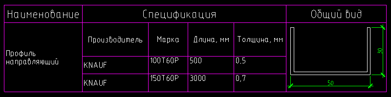
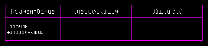
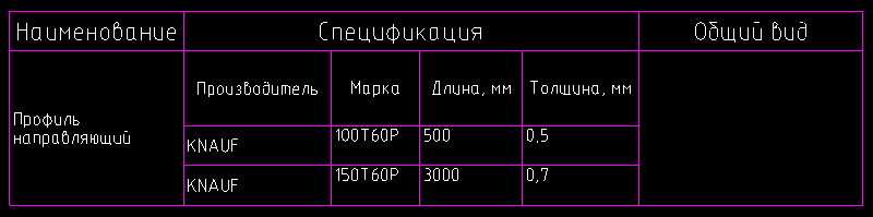
In MultiCAD.NET tables, in addition to ordinary text and numeric data, blocks and other tables can be used as cell contents. Consider this possibility by the example of creating a table that will describe the elements of the metal profile. The profile type will be indicated in the first column, its specification in the second, profile image in the third:
Suppose that the profile type specification is stored in the form of a table of the following form:

A general view of the various profiles in an external file as separate blocks:

Add to the main profile picture table and its specification.
Subtables Insert
To insert sub
McTable.InsertSubtable(ref McTable inTable, int row, int col, InsertionModeEnum mode);inTable-tables, use the method - the table to be inserted row, col- the row and column number of the cell into which the insert will be performed mode- the table insert mode. The insertion modes can be as follows:
InSingleCell- the table will be inserted into a separate cell. In this case, the structure of the resulting table will be changed in accordance with the structure of the inserted table. CellByCell- the table will be inserted "cell into cell", starting with the upper left. The resulting table will contain those cells that are common to the structures of both tables. Over- the table will be inserted on top. Cell sizes of both tables are not changed. Insert the profile specification table in a separate cell of the main table:
Table1.InsertSubtable(ProfileTable1, 1, 1, InsertionModeEnum.InSingleCell);
Blocks as cell contents
To insert a block, use the
EmbedBlock()class method Cell, which allows you to embed the block in a separate cell by specifying the block ID, its name or the name of the block and the name of the file that contains it: bool EmbedBlock(int row, int col, McObjectId Id); bool EmbedBlock(int row, int col, ref String name); bool EmbedBlock(int row, int col, ref String name, ref String fileName); Insert the image of the guide profile, which is stored in an external file as a block:
Table1[1, 0].Value = "Профиль направляющий";
Table1[1, 2].EmbedBlock("Profile_03", "C:\\Profiles.dwg");
Retrieving object properties in a table
Another useful feature of the table API in MultiCAD.NET is the binding of primitives to the table. After the object is attached to the table, you can use its properties as the contents of the cell using formulas. The following code fragment attaches a closed polyline to the table and receives as the cell content (0, 0) the value of the area bounded by the polyline:
String object = Table1.AttachObject(polyline.ID);
Table1[0, 0].ValueFormula = object + ".\"Geometry.Area\"";
The binding of objects to the table allows you to dynamically track changes: when the properties of the attached object change, the contents of the corresponding cell will also change.
Discussion of the article is also available on our forum: forum.nanocad.ru/index.php?showtopic=6511 .
Translation of the article into English: Tables in MultiCAD.NET. Part 2: Creating and modifying .
See also:
Working with tables in MultiCAD.NET. Part 1. Creating a report based on the template
Working with tables in MultiCAD.NET. Part 3. External table files and data exchange with Microsoft Excel