How easy it is for an artisan to dream with a 3D core
How a 3D geometric kernel is used when developing applications for CAD, says Valery Golovanev, an analyst and programmer, an application developer for KOMPAS-3D. With a lyrical introduction and deep immersion in the world of mechanical transmissions.
My great-great-great-great-grandfather Efim Stepanovich (a plowman, a cooper and a joiner), my great-grandfather Trifon Efimovich (a plowman and a carpenter) and my grandfather Mikhail Trifonovich (a blacksmith, a carpenter, a joiner, a cooper) were masterful. And I am a master person. Engineer and amateur carpenter.
It is difficult for any craftsman ... It is difficult without interesting tasks, it is difficult when there are not enough opportunities for their implementation. In the nature of a real artisan person, set himself tasks, sometimes seemingly not feasible, and implement them.
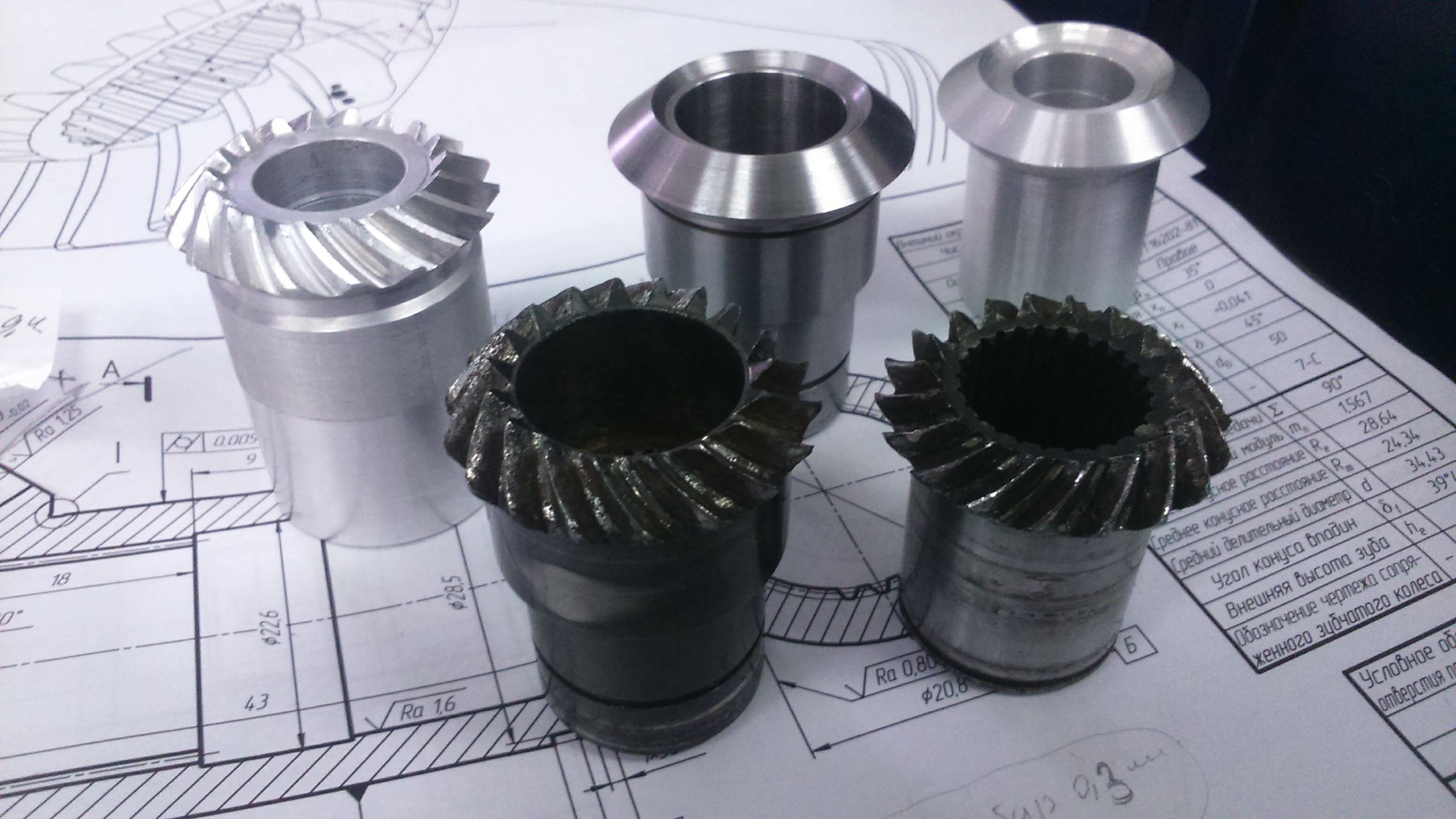
When six years ago, in the summer of 2012, I returned to my brainchild - the KOMPAS-Shaft design library for bodies of rotation (now the application “Shafts and mechanical 3D transmissions” for KOMPAS-3D), then I printed a pair of circular teeth with my tooth on the IP stamp . At that moment I only dreamed that someday I could make them in 3D - it was rather a kind of symbol. With age, you treat the signs and symbols of fate more carefully ... The goal was materialized!
How did it all start? With desire! I really wanted to give the designer real 3D-models of mechanical gears, and not some kind of “similarity”, so that you can:
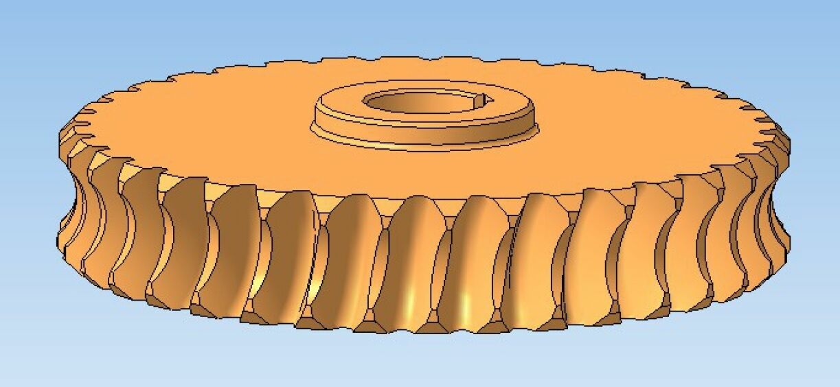
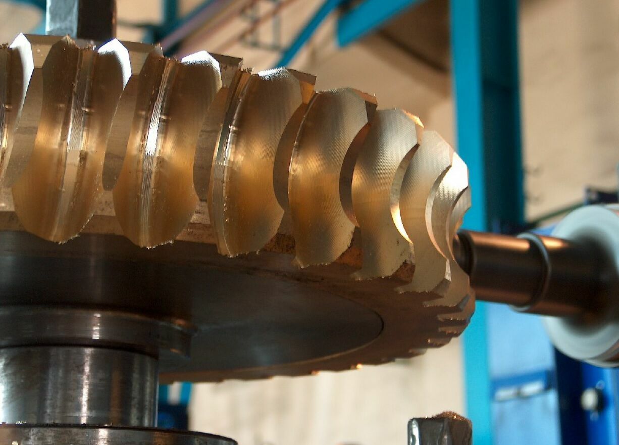
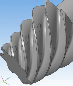
It took about three years and in the spring of 2015 I decided to make a real worm wheel using the API KOMPAS. The principle of implementation in this task was clear to me for a long time: it is necessary to sweep the workpiece with a tool, that is, an imitation of machining in KOMPAS-3D. Not to say that it was easy. Cutting a set of multiple tool positions is incorrect and long. It is necessary to form a set of surfaces of tool positions and create an envelope surface of the cutout along them. Which in general happened, but it worked very slowly.
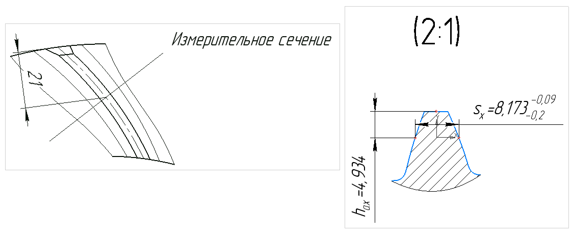
In addition, it was necessary to add realism to the process, that is, to take into account the tolerances in the formation of 3D geometry. In general, having solved one problem, I wanted more - greater accuracy, measurements of the worm wheel tooth and the formation of callouts in the drawings with the profile of this tooth (and suddenly toolmakers want to make measuring templates?). By the way, in the same year, at the Kazzincmash plant, according to my models, two pairs of worm wheels were manufactured, which were successfully put into work units and received positive feedback.
Go ahead! In the fall of 2015, with the filing (or kick-off) of Vladimir Panchenko, head of the KOMPAS-3D Application, and under the care of Alexey Sultanov, I began to learn programming on the C3D core, on which KOMPAS-3D was built. The goal is to get freedom! And I got it. I was no longer limited by the number of operations and procedures performed. Everything happened fast enough. At the exit, I had a body - an array of cuts from the worm wheel blank. Well, then everything is simple: the Boolean operation and the worm wheel is ready. Nikolay Golovanov, Head of C3D Labs Development

This was followed by cylindrical external engagement. It would seem simple, but meanwhile, in the case of a helical wheel and the screw cut operation in API KOMPAS-3D, it was also built long enough. Now these gears can be formed with a real backing.
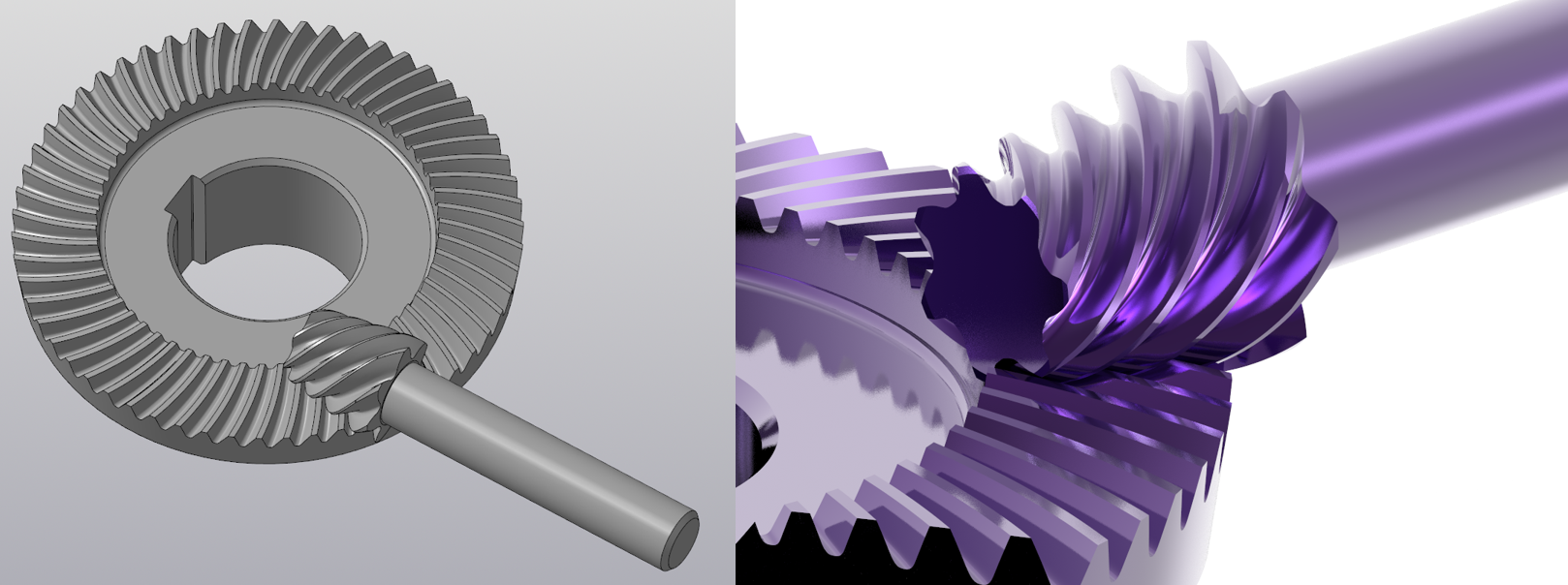
Well, at the end of 2015 started the process of working on the ridges with a circular tooth.
The algorithm at that time was worked out by the API COMPAS. The first models with not very good geometry were formed before the day of pure time. Here, one sweeping surfaces did not do. The conical bevel gears were created, and it was necessary to form a wheel, having processed it with a prototype gear-cutting head. Then, using the obtained 3D geometry, form and save a prototype of a gear tool, remove controlled dimensions from all of this and transfer them to a drawing. Further, already on the gear, given that it turned out to be perfectly round, it was necessary to localize the contact, i.e., to ensure the correct position and size of the contact patch in the gear.
Difficult and very interesting task. Occasionally, Nikolai Golovanov and his team ruled according to my remarks the C3D functional. Thus, my horses were also a good test for the core. Nikolay Golovanov, Head of C3D Labs Development
Konichki on my models were made repeatedly at different enterprises and work in real nodes. Improved localization algorithm.

But it was hard to stop at that. I did not like this localization. It was too difficult to provide it. And in the spring of 2018 came the idea of a more “simple” method of localization. Actually, the idea is not mine, I spied it in the materials of the Klingelnberg company - they have it called profile and lengthwise crowning .
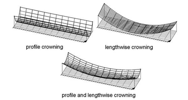
I called it "make a tooth with a mound", which is what happened. In each section of the profile of the notch, its recalculation was made, and the mound was a success. Localization coefficients have become simpler and easier to understand.
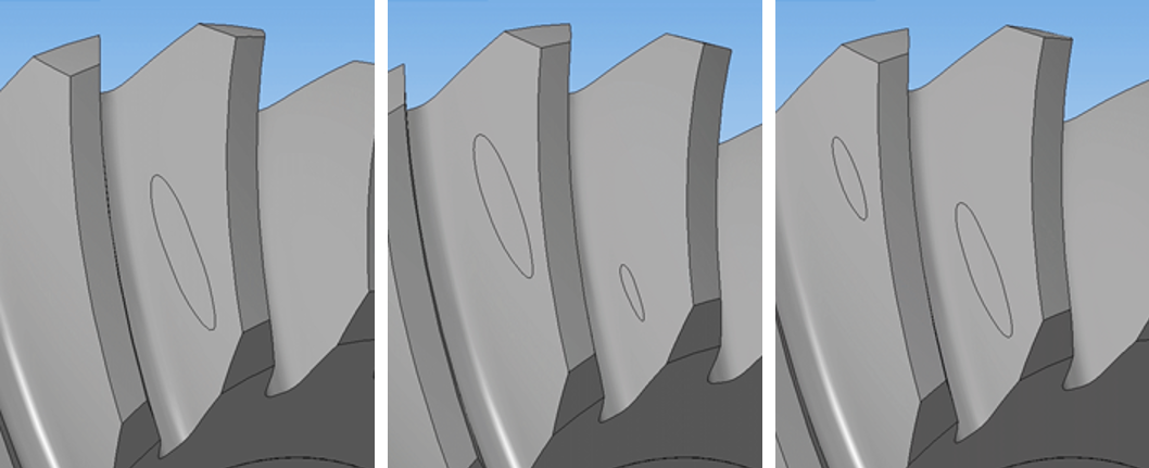
Briefly about the result: a contact patch, and this is a set of instant contact sites on a gear tooth in one cycle of its rotation = 360 / number of gear teeth, NOW ALWAYS is in the middle of the active tooth surface (at the top of the hillock), its size is more than 60% the entire surface.
To make them, however, so far it will turn out only on the CNC, but in the future, additive technologies will also catch up.
Well, the curtain ... This year, the dream transfer is realized, my most difficult dream today is the hypoid gears. Much that had to be done for this ... Six years on the way back to the development of CAD. Although in fact the way began in 1991 with a custom project to create software for calculating bevel gears with a circular tooth.
Naturally, the tooth "knoll" is implemented in them. Vladimir Panchenko, Head of KOMPAS-3D Application Division, ASCON

The most usual operations are used from the core's functional: create a plane, construct a sketch / surface / intersection of surfaces, etc.
For example, consider the sequence of operations necessary to form a 3D model of a tapered wheel cutout with circular teeth (namely wheels, not gear wheels):
What else does a craftsman need in this case? Spatial imagination, fantasy and the ability to dream in the end! Vladimir Panchenko, Head of KOMPAS-3D Application Division, ASCON
 Valery Golovanev , engineer-analyst and programmer, Kurgan, pos. Teply Stan.
My great-great-great-great-grandfather Efim Stepanovich (a plowman, a cooper and a joiner), my great-grandfather Trifon Efimovich (a plowman and a carpenter) and my grandfather Mikhail Trifonovich (a blacksmith, a carpenter, a joiner, a cooper) were masterful. And I am a master person. Engineer and amateur carpenter.
It is difficult for any craftsman ... It is difficult without interesting tasks, it is difficult when there are not enough opportunities for their implementation. In the nature of a real artisan person, set himself tasks, sometimes seemingly not feasible, and implement them.
When six years ago, in the summer of 2012, I returned to my brainchild - the KOMPAS-Shaft design library for bodies of rotation (now the application “Shafts and mechanical 3D transmissions” for KOMPAS-3D), then I printed a pair of circular teeth with my tooth on the IP stamp . At that moment I only dreamed that someday I could make them in 3D - it was rather a kind of symbol. With age, you treat the signs and symbols of fate more carefully ... The goal was materialized!
From the worm wheel to hypoid gear in KOMPAS-3D
How did it all start? With desire! I really wanted to give the designer real 3D-models of mechanical gears, and not some kind of “similarity”, so that you can:
- Produce a gear or worm wheel or sprocket using a 3D model. Or konchku with a circular tooth, or (about a dream ...) a hypoid pair.
- To see in the 3D-assembly not conditional “crocosybras”, but real models.
- And further ... And why, in fact, it is necessary to focus in mechanical gears on the possibility (limitation) of the usual technology? It is wrong to infringe a design with technology. It is necessary to make the right gear with the optimal 3D-geometry of the active working surfaces from the point of view of operation, and the technology should ensure their production. And this technology, called additive, already exists! Modern industrial 3D printers make it possible for metal to print fully loaded products, and experiments go far: details created by an additive method soon will be an ordinary phenomenon in a machine-building product, if not mass, then in small-scale - for sure.
It took about three years and in the spring of 2015 I decided to make a real worm wheel using the API KOMPAS. The principle of implementation in this task was clear to me for a long time: it is necessary to sweep the workpiece with a tool, that is, an imitation of machining in KOMPAS-3D. Not to say that it was easy. Cutting a set of multiple tool positions is incorrect and long. It is necessary to form a set of surfaces of tool positions and create an envelope surface of the cutout along them. Which in general happened, but it worked very slowly.
In addition, it was necessary to add realism to the process, that is, to take into account the tolerances in the formation of 3D geometry. In general, having solved one problem, I wanted more - greater accuracy, measurements of the worm wheel tooth and the formation of callouts in the drawings with the profile of this tooth (and suddenly toolmakers want to make measuring templates?). By the way, in the same year, at the Kazzincmash plant, according to my models, two pairs of worm wheels were manufactured, which were successfully put into work units and received positive feedback.
Go ahead! In the fall of 2015, with the filing (or kick-off) of Vladimir Panchenko, head of the KOMPAS-3D Application, and under the care of Alexey Sultanov, I began to learn programming on the C3D core, on which KOMPAS-3D was built. The goal is to get freedom! And I got it. I was no longer limited by the number of operations and procedures performed. Everything happened fast enough. At the exit, I had a body - an array of cuts from the worm wheel blank. Well, then everything is simple: the Boolean operation and the worm wheel is ready. Nikolay Golovanov, Head of C3D Labs Development

Some applications of the KOMPAS-3D system, including the application “Shafts and mechanical 3D transmissions”, work directly with the geometric core C3D. This allows application developers to approach their tasks more flexibly by expanding the functionality (working with low-level functions) and building geometric objects.
If you are writing an application for KOMPAS-3D and you want to use C3D features directly, it makes sense to contact the kernel that is built into KOMPAS-3D itself. This method has the only restriction: it is necessary to use only C ++, since COMPASS itself is written in this language. If you decide to work with a separate copy of the kernel within your own application, then C # and, in some cases, JavaScript will be available to you.
This was followed by cylindrical external engagement. It would seem simple, but meanwhile, in the case of a helical wheel and the screw cut operation in API KOMPAS-3D, it was also built long enough. Now these gears can be formed with a real backing.
Well, at the end of 2015 started the process of working on the ridges with a circular tooth.
The algorithm at that time was worked out by the API COMPAS. The first models with not very good geometry were formed before the day of pure time. Here, one sweeping surfaces did not do. The conical bevel gears were created, and it was necessary to form a wheel, having processed it with a prototype gear-cutting head. Then, using the obtained 3D geometry, form and save a prototype of a gear tool, remove controlled dimensions from all of this and transfer them to a drawing. Further, already on the gear, given that it turned out to be perfectly round, it was necessary to localize the contact, i.e., to ensure the correct position and size of the contact patch in the gear.
Difficult and very interesting task. Occasionally, Nikolai Golovanov and his team ruled according to my remarks the C3D functional. Thus, my horses were also a good test for the core. Nikolay Golovanov, Head of C3D Labs Development
Recently, the geometric core C3D underwent a substantial processing of Loft-surfaces, built on sections. They were used to simulate the contact points of gears.
Konichki on my models were made repeatedly at different enterprises and work in real nodes. Improved localization algorithm.
But it was hard to stop at that. I did not like this localization. It was too difficult to provide it. And in the spring of 2018 came the idea of a more “simple” method of localization. Actually, the idea is not mine, I spied it in the materials of the Klingelnberg company - they have it called profile and lengthwise crowning .
I called it "make a tooth with a mound", which is what happened. In each section of the profile of the notch, its recalculation was made, and the mound was a success. Localization coefficients have become simpler and easier to understand.
Briefly about the result: a contact patch, and this is a set of instant contact sites on a gear tooth in one cycle of its rotation = 360 / number of gear teeth, NOW ALWAYS is in the middle of the active tooth surface (at the top of the hillock), its size is more than 60% the entire surface.
What it gives:
- transmissions will be more durable and reliable
- reduced noise in the transmission
- transmission will be less sensitive to mounting errors.
To make them, however, so far it will turn out only on the CNC, but in the future, additive technologies will also catch up.
Well, the curtain ... This year, the dream transfer is realized, my most difficult dream today is the hypoid gears. Much that had to be done for this ... Six years on the way back to the development of CAD. Although in fact the way began in 1991 with a custom project to create software for calculating bevel gears with a circular tooth.
Naturally, the tooth "knoll" is implemented in them. Vladimir Panchenko, Head of KOMPAS-3D Application Division, ASCON

The use of the nucleus in the application "Shafts and mechanical transmissions" prompted the recall of Kazzincmash. It was obvious to me that it was possible to build quickly, it remained only to convince Valery of this. An aggravating circumstance was that Valery did not like C ++, and the use of C3D functions in the context of KOMPAS-3D is possible only in this programming language. I had to do the layout, thanks to Alexey Sultanov.
A simple translation of the code into the forehead immediately gave a tangible gain in speed: the exact model of the worm wheel tooth was built in 10 seconds. The worm wheel was built on the API for about an hour.
Well, after Valery's skill allowed to create and konchiki with a circular tooth.
That's how we raised the project "Shafts and mechanical transmissions" to a whole new level.
How the 3D core works in mechanical gear modeling
The most usual operations are used from the core's functional: create a plane, construct a sketch / surface / intersection of surfaces, etc.
For example, consider the sequence of operations necessary to form a 3D model of a tapered wheel cutout with circular teeth (namely wheels, not gear wheels):
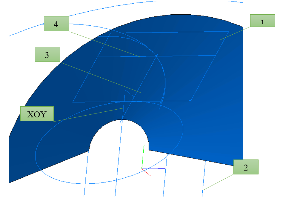
- We form the surfaces of the cones - the separating cone, the cone of the peaks and the cone of the depressions. To do this, planes are created at the corresponding calculated distances, and sketches of circles of calculated diameters are built on them, and cones are already drawn along them.
- We build the points of the centers of the divisor cone and the cone of the depressions.
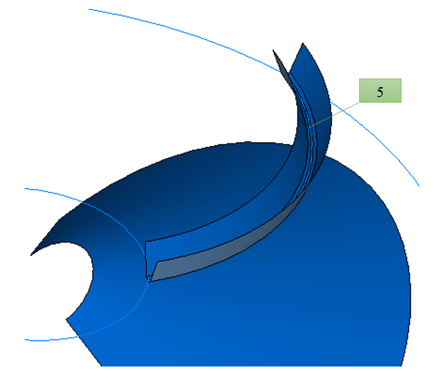
- Next, a tangent plane to the cone of the troughs (1) and a plane along the midpoint of the wheel in the trough (2) are formed. The intersection of the plane (1) and the XOY plane forms the axis of intersection (3), and the intersection of the plane (2) and the plane (1) forms the axis of intersection (4).
- At the intersection of these axes there will be a point through which the top of the gear-cutting head passes.
- From this point, knowing the average angle of inclination of the teeth (just at this point), we calculate the center of the gear-cutting head.
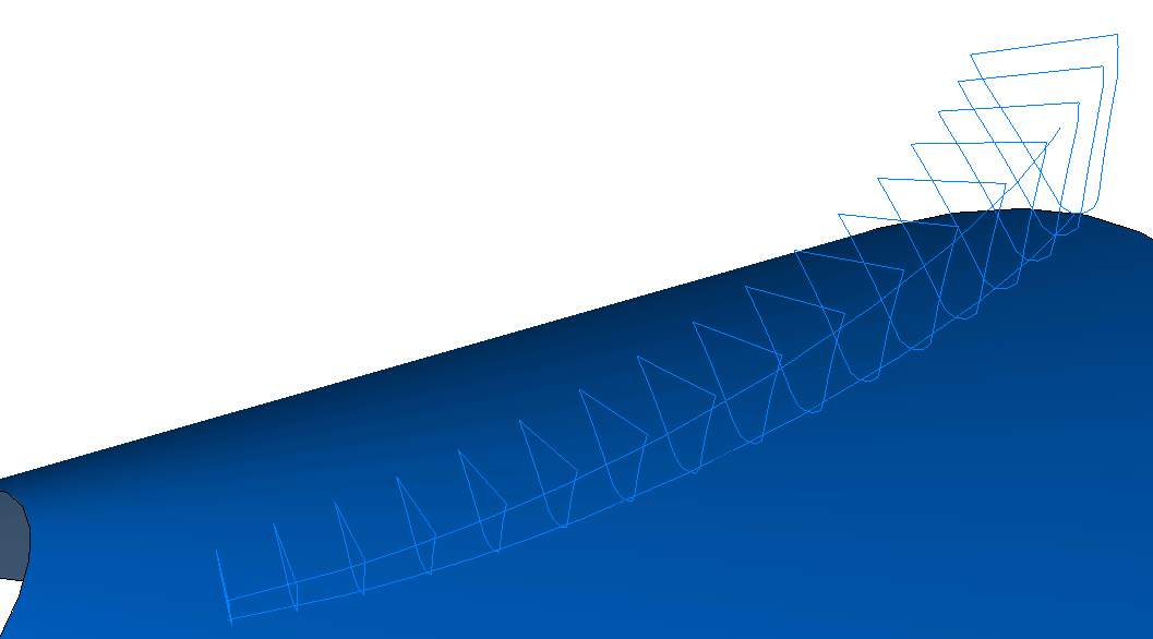
- The projections of the half-arc of the gear-cutting head onto the cones of the depressions (5) and the dividing cone will be our guides. On this guide (5) the base surface of the cutout will be built (loft in three sections with the calculated profile of the gear cutter).
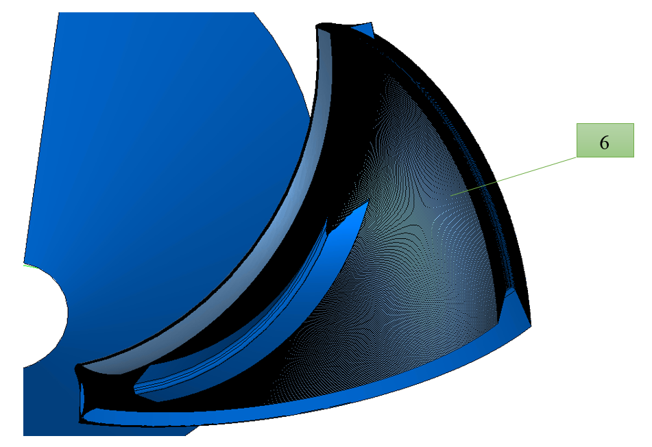
- Further, having a procedure for performing a similar operation at different angles of swing of the gear-cutting head when machining the wheel, we obtain an array of cut surfaces (6).
- After that, in a sufficient number of sections (not less than 20) in normal planes to the guide (the projection of the half-arc of the gear-cutting head on the dividing cone) will be obtained sets of intersection lines of the array of surfaces.
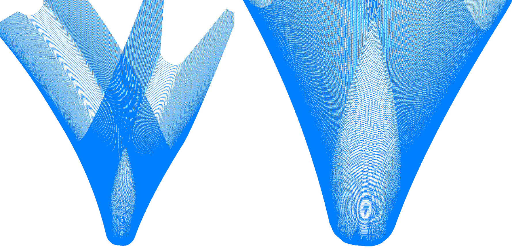
- Mathematical processing of the obtained set of intersection lines will allow us to obtain their envelope, which will be one of the sections of the actual tooth cut-out of the wheel.
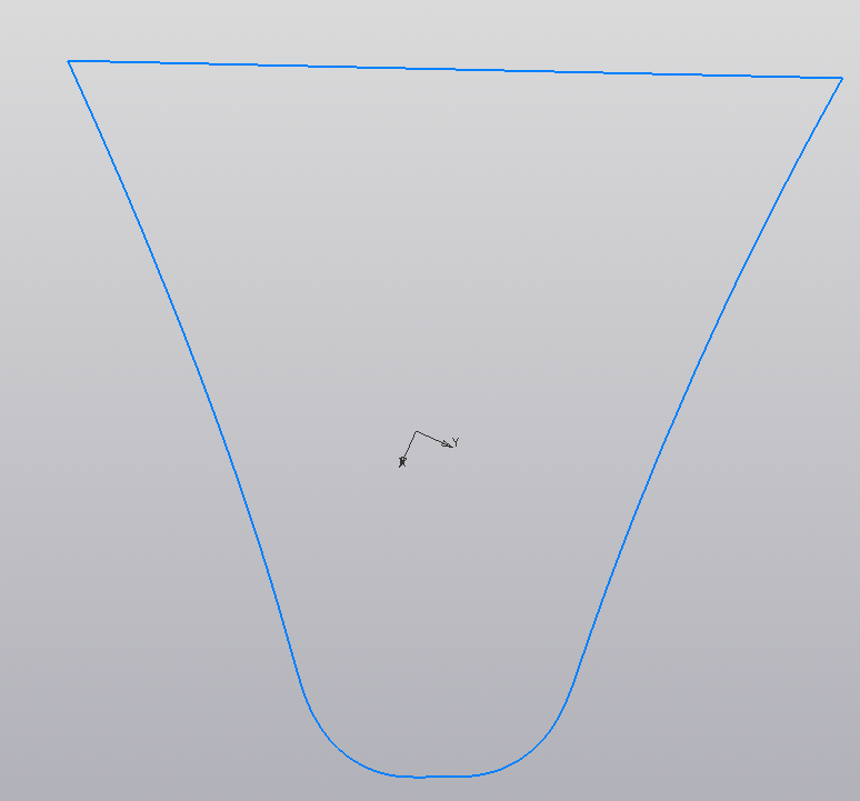
- The totality of these sections of the cut-outs will be the final loft - cut-out of the tooth of the wheel.
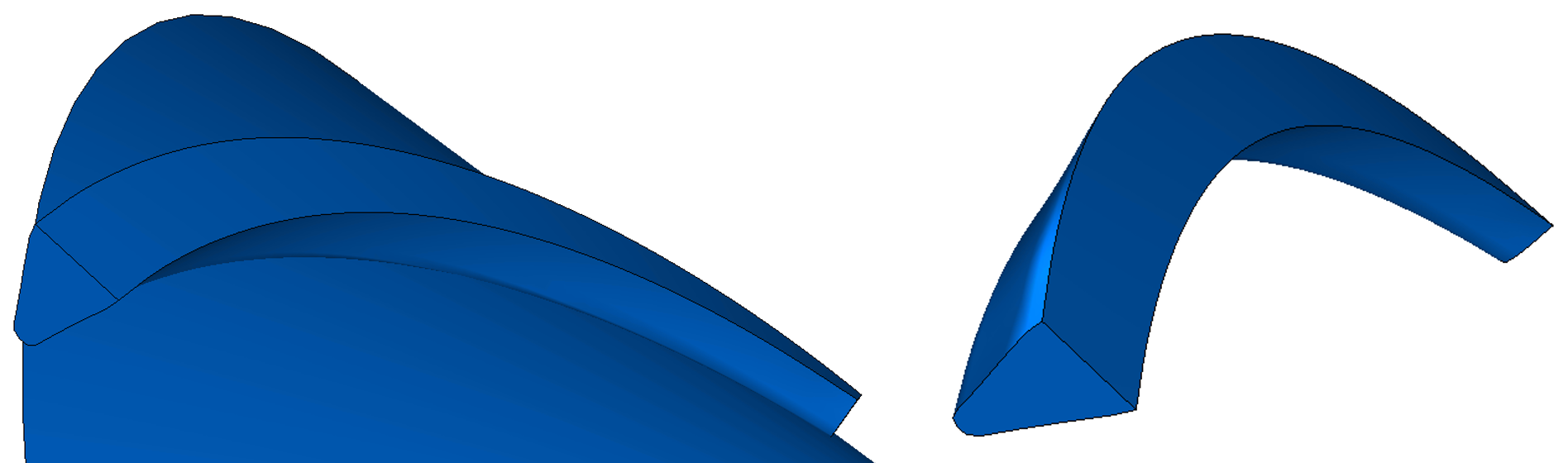

- The resulting geometry will be automatically removed (a tooth is built, a section is made with a cutting plane and calculated on it) the control dimensions, the tooth profile itself, and all this is transferred to the drawing.
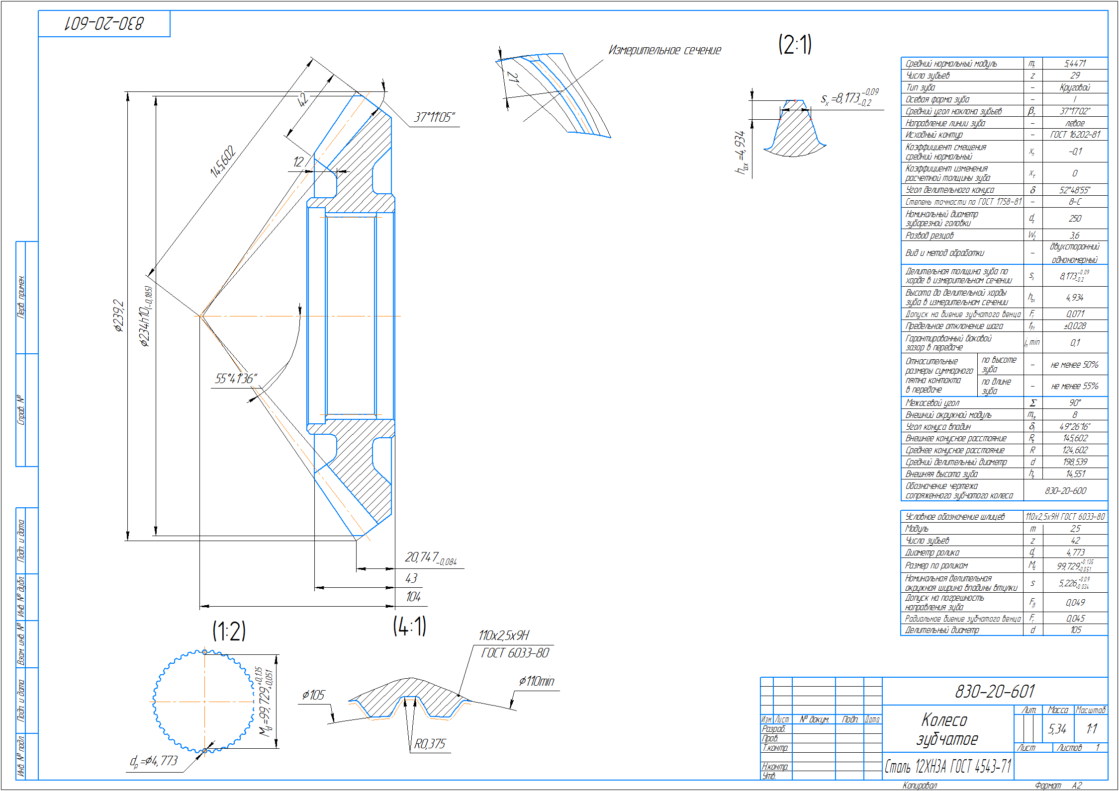
- Everything is quite simple, though in this particular case and without considering the “small” nuances of mathematical calculations hidden from the eyes of readers.
What else does a craftsman need in this case? Spatial imagination, fantasy and the ability to dream in the end! Vladimir Panchenko, Head of KOMPAS-3D Application Division, ASCON
What is faster API KOMPAS-3D or C3D? The question sounds paradoxical. C3D is the geometric core of KOMPAS-3D! As the core works, so does KOMPAS-3D. But on closer examination, especially in the context of an application developer, everything falls into place.
The standard scheme for the developer looks like this. Calling the API function KOMPAS-3D leads to the addition of an object to the document model, and then C3D is called to create the geometry. Then, in a chain, in reverse order, the data is returned back to the API, and here in the hands of the developer the interface of the created object.
At the same time, something happens with the data at each step: in the API they are packaged in COM, in the document model they are checked for correctness in the current context, and attributes and drawing data are added. Of course, all these actions are optimized and take very little time. If the developer needs to get a cylindrical shaft step, then he creates a sketch and an extrusion operation in KOMPAS-3D - just two objects and two chaining. But the situation is fundamentally changing in the case of the geometry for a bevel gear with a circular tooth. To do this, you need to create a lot of auxiliary curves, surfaces (and all this is not analytical cylinders and cones, but NURBS), their intersections. Data pumping begins to take significant time already. The core will be mostly idle. To avoid temporary losses interaction with the API and the document model is minimized - add an operation with the body and accept the body that is modeled in C3D. We get one run in C3D and optimally create all auxiliary geometry on the stack, intersect what we need and get the result. Only the kernel works and works very quickly.
 Valery Golovanev , engineer-analyst and programmer, Kurgan, pos. Teply Stan.