A simple 4-color multi-channel garland based on the ATTINY13A microcontroller
As the people say - prepare a sled in the summer ...
Surely for the New Year you decorate the Christmas tree with all kinds of garlands, and most likely they have long ago become boring with the monotony of their flashing. I would like to do something so that wink, just like in the capital's Christmas trees, blinked, only on a smaller scale. Or, in extreme cases, hang it on the window so that this beauty directly illuminates the city from the 5th floor.
But alas, there are no such garlands on sale.
Actually, it was precisely this problem that had to be solved two years ago. Moreover, because of laziness from the idea to implementation, 2 years passed as usual, and everything was done in the last month. Actually, you will have more time (or I don’t understand anything in human psychology, and everything will be done exactly the same in the last 2 weeks before the new year?).
The result was a fairly simple design of separate modules with LEDs, and one common one that transmits commands from a computer to the network of these modules.
The first version of the module was conceived in such a way that they were connected to the network via two wires, so that there was less confusion and all that didn’t grow together, as a result, a rather powerful and high-speed switch was required to switch the power of even a small number of modules - an obvious bust for simplicity of design, therefore the third wire is not so convenient, but it is much easier to organize a data transmission channel.
How it works.
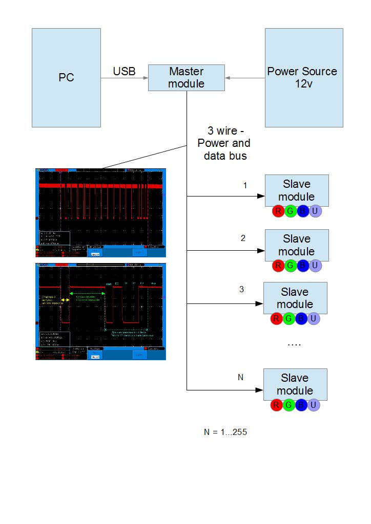
The developed network is capable of addressing up to 254 slave modules, which will be called SLAVE hereinafter - they are connected by only 3 wires, as you might have guessed - two wires are + 12V power, the common and the third are signal.
they have a simple scheme:
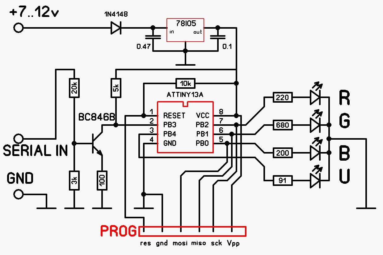
As you can see, it supports 4 channels - Red, Green, Blue and Purple.
True, according to the results of practical testing, purple is clearly visible only near but how! Also, due to the fact that the colors are too far from each other, color mixing can only be seen from 10 meters, if you use RGB LEDs, the situation will be slightly better.
In order to simplify the design, I also had to abandon quartz stabilization - firstly, the extra output takes away and secondly, the cost of the quartz resonator is quite noticeable and thirdly - there is no urgent need for it.
A protective cascade is assembled on the transistor so that the controller port does not knock out the static - the line can still be quite long, in the extreme case only the transistor will suffer. The cascade is designed in MicroCap and has an approximate response threshold of about 7 volts and a weak dependence of the threshold on temperature.
Naturally, in the best traditions, all modules respond to the address number 255 - so you can turn them off all at once with one command.
A module called MASTER is also connected to the network - it is an intermediary between a PC and a network of slave SLAVE modules. Among other things, it is a source of exemplary time for synchronizing slave modules in the absence of quartz stabilization in them.
Scheme:
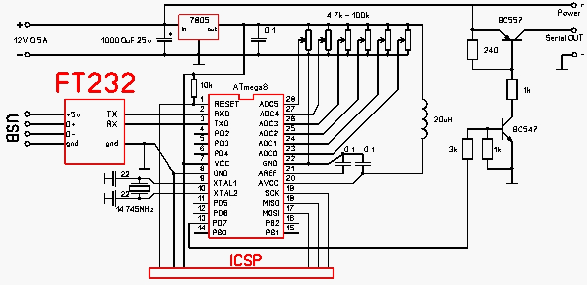
There are optional potentiometers in the circuit - they can be used in a PC program for convenient and quick adjustment of the desired parameters, at the moment this is implemented only in a test program in the form of the ability to assign any of the 4 channels to any of the potentiometers. The circuit is connected to a PC via a USB-UART interface converter on an FT232 chip.
An example of a packet issued to the network:

Its beginning:

Electrical characteristics of the signal: log.0 corresponds to +9 ... 12V, and log.1 corresponds to 0 ... 5V.
As you can see, the data is transmitted sequentially, with a fixed speed of 4 bits. This is due to the necessary margin for error in the data reception rate - SLAVE modules do not have quartz stabilization, and this approach guarantees data reception when the transmission rate deviates up to + -5% in excess of those that are compensated by the software method based on measuring the calibrated interval at the beginning of data transfer which gives resistance to the departure of the reference frequency by another + -10%.
Actually, the algorithm of the MASTER module is not so interesting (it is quite simple - we receive data on UART and forward it to a network of slaves), all the most interesting solutions are implemented in SLAVE modules, which actually allow you to adjust to the transmission speed.
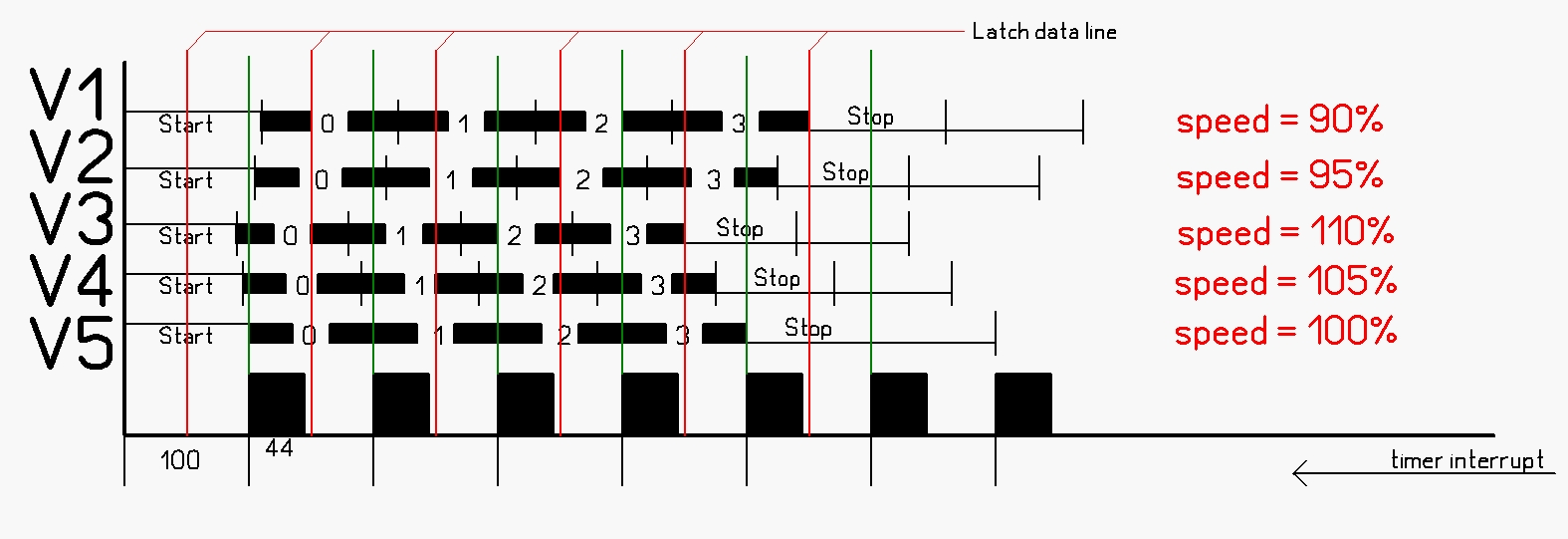
The main and most important algorithm is the implementation of 4-channel 8-bit PWM software that allows you to control 4 LEDs with 256 gradations of brightness of each of them. The implementation of this algorithm in hardware also determines the data transfer speed in the network - for software convenience, one bit is transmitted for each step of the PWM operation. A preliminary implementation of the algorithm showed that it runs for 44 cycles, so it was decided to use a timer configured to interrupt every 100 cycles - this way the interruption is guaranteed to be executed before the next one and to execute part of the main program code.
At a selected internal oscillator clock frequency of 4.8 MHz, interruptions occur at a frequency of 48 kHz - this is the bit rate of the network of slaves and the PWM is filled at the same speed - as a result, the frequency of the PWM signal is 187.5 Hz, which is enough to not notice the flickering of the LEDs. Also, in the interrupt handler, after the execution of the algorithm responsible for the PWM generation, the data bus status is fixed - it turns out approximately in the middle of the timer overflow interval, this simplifies data reception. At the beginning of receiving the next 4-bit packet, the timer is reset to zero, this is necessary for more accurate synchronization of reception and resistance to deviation of the reception speed.
The result is the following picture:
An interesting implementation of the tuning algorithm for the transmission speed. At the beginning of the transmission, MASTER generates a pulse with a duration of 4 bits of log.0, according to which all slave modules determine the necessary reception speed using a simple algorithm:
st_syn_delay = 60 - a constant that determines the maximum duration of the start pulse, which is taken about 2 times the nominal value (for reliability). The
experimental method established the dependence of the received number in tmp2 when the clock frequency deviates from the nominal value:
4.3Mhz (-10%) 51 units (0x33) corresponds to 90 clock ticks to return the reception speed to the nominal
4.8Mhz (+ 00%) 43 units (0x2B) - corresponds to 100 clock
ticks ( nominal) 5.3Mhz (+ 10%) 35 units (0x23) - corresponds to 110 clock ticks to return to the nominal receiving rate
on these Dunn m were calculated correction coefficients timer interrupt period (in this way adapts reception rate controller available clock frequency):
Y (x) = 110-x * 20/16
x = tmp2 - 35 = (0, 1, 2, 3, 4, 5, 6, 7, 8, 9, 10, 11, 12, 13, 14, 15, 16)
Y (x) = (110, 108.75 , 107.5, 106.25, 105, 103.75, 102.5, 101.25, 100, 98.75, 97.5, 96.25, 95, 93.75, 92.5, 91.25, 90)
The numbers are rounded to the nearest integer and entered in the EEPROM.
If you keep the line in logical state “1” when applying voltage to the module, the calibration subroutine will turn on, which will allow you to measure the period of the PWM signal with a frequency meter or an oscilloscope without correction and judge the deviation of the module controller clock frequency from the nominal one based on measurements, with a strong deviation of more than 15% correction of the calibration constant of the built-in RC generator may be required. Although the manufacturer promises calibration at the factory and a deviation from the nominal no more than 10%.
At the moment, a program on Delphi has been developed allowing to reproduce a previously composed pattern for 8 modules with a given speed. As well as a utility for working with a separate module (including reassignment of the module address).
Firmware.
for the SLAVE module, it is only necessary to flash the fuses CKSEL1 = 0, and SUT0 = 0. The rest should be left unbroken. Flash the contents of the EEPROM from the RGBU-slave.eep file, if necessary, you can immediately set the desired module address on the network - the 0th byte of the EEPROM, by default it is flashed as $ FE = 254, the address 0x13 contains the calibration constant of the built-in RC generator of the controller, at a frequency of 4.8 MHz it does not load automatically; therefore, it is necessary to read the factory calibration value and write to this cell as a programmer - this value is individual for each controller; if the frequency deviates from the nominal value, calibration can be changed through this cell agivaya factory values.
for the MASTER module, it is only necessary to flash the fuses SUT0 = 0, BOOTSZ0 = 0, BOOTSZ1 = 0, CKOPT = 0. The rest should be left unbroken.
Finally, a small demonstration of a garland located on the balcony:
In fact, the functionality of the garland is determined by the program on the PC - you can make color music, stylish iridescent lighting in the room (if you add LED drivers and use powerful LEDs) - etc. What I plan to do in the future. The plans include a grid of 12 modules with 3-watt RGB LEDs, and room lighting based on pieces of 12-volt RGB tape (only field-effect transistors are needed to switch the tape to each module for 3 pieces or 4 if you add a piece of purple tape other than the original will not be).
To manage the network, you can write your own program, even in BASIC - the main thing that the selected programming language should do is be able to connect to immortal COM ports and configure their parameters. Instead of a USB interface, you can use an adapter with RS232 - this gives the potential to control lighting effects from a wide range of devices that can generally be programmed.
The protocol for exchanging with the MASTER device is quite simple - we send a command and expect an answer about its success or failure, if there is no answer for more than a few milliseconds - there are problems with the connection or operation of the MASTER device, in which case it is necessary to carry out the reconnection procedure.
The following commands are currently available:
0x54; symbol "T" - command "test" - test the connection, the response should be 0x2B.
0x40; the "@" symbol is the upload and transfer command. After giving the command you need to wait for the answer "?" 6 data bytes follow:
+0: Slave address 0..255
+1: Device command
0x21 - bytes 2 ... 5 contain the brightness on the channels that must be applied immediately.
0x14 - set a timeout after which the brightness across all channels will be
reset to 0 if no commands are received during this time. The timeout value is in the red channel cell, i.e. in a byte with an offset of +2. the value 0-255 corresponds to a timeout of 0-25.5 seconds by default, timeout = 5 seconds (recorded in the EEPROM during firmware, it can also be changed in the byte with an offset of +1).
0x5A - change device address.
The procedure for changing the address for reliability should be performed three times - only then the new address will be applied and registered in the EEPROM. In this case, one must be careful - if you register two devices with the same address, they will respond synchronously, and they can be "split" only by physically disconnecting the excess modules from the network and changing the address of the remaining one, or by the programmer. The value of the new address is transmitted in the red channel cell - i.e. in a byte with an offset of +2.
+2: Red brightness 0 ... 255
+3: Green brightness 0 ... 255
+4: Blue brightness 0 ... 255
+5: Purple brightness 0 ... 255
0x3D; the symbol "=" is the "ADC" command. After giving the command you need to wait for the answer "?" then 1 byte should be transferred - the ADC channel number 0..7 in binary form (ASCII digits 0..9 are also suitable in this quality, since the most significant 4 bits are ignored).
In response, the command returns 2 bytes of the measurement result in the range 0 ... 1023
Possible answers to the commands:
0x3F; character "?" - readiness for data entry, means that the device is ready to receive the arguments of the
0x2B command; character "+" Answer - command executed
0x2D; symbol "-" Answer - the command is not defined or erroneous.
More details can be fished out from the sources located on the github, there are also the latest versions of ready-made firmware: github.com/Alexeyslav/RGBU_light
Surely for the New Year you decorate the Christmas tree with all kinds of garlands, and most likely they have long ago become boring with the monotony of their flashing. I would like to do something so that wink, just like in the capital's Christmas trees, blinked, only on a smaller scale. Or, in extreme cases, hang it on the window so that this beauty directly illuminates the city from the 5th floor.
But alas, there are no such garlands on sale.
Actually, it was precisely this problem that had to be solved two years ago. Moreover, because of laziness from the idea to implementation, 2 years passed as usual, and everything was done in the last month. Actually, you will have more time (or I don’t understand anything in human psychology, and everything will be done exactly the same in the last 2 weeks before the new year?).
The result was a fairly simple design of separate modules with LEDs, and one common one that transmits commands from a computer to the network of these modules.
The first version of the module was conceived in such a way that they were connected to the network via two wires, so that there was less confusion and all that didn’t grow together, as a result, a rather powerful and high-speed switch was required to switch the power of even a small number of modules - an obvious bust for simplicity of design, therefore the third wire is not so convenient, but it is much easier to organize a data transmission channel.
How it works.
The developed network is capable of addressing up to 254 slave modules, which will be called SLAVE hereinafter - they are connected by only 3 wires, as you might have guessed - two wires are + 12V power, the common and the third are signal.
they have a simple scheme:
As you can see, it supports 4 channels - Red, Green, Blue and Purple.
True, according to the results of practical testing, purple is clearly visible only near but how! Also, due to the fact that the colors are too far from each other, color mixing can only be seen from 10 meters, if you use RGB LEDs, the situation will be slightly better.
In order to simplify the design, I also had to abandon quartz stabilization - firstly, the extra output takes away and secondly, the cost of the quartz resonator is quite noticeable and thirdly - there is no urgent need for it.
A protective cascade is assembled on the transistor so that the controller port does not knock out the static - the line can still be quite long, in the extreme case only the transistor will suffer. The cascade is designed in MicroCap and has an approximate response threshold of about 7 volts and a weak dependence of the threshold on temperature.
Naturally, in the best traditions, all modules respond to the address number 255 - so you can turn them off all at once with one command.
A module called MASTER is also connected to the network - it is an intermediary between a PC and a network of slave SLAVE modules. Among other things, it is a source of exemplary time for synchronizing slave modules in the absence of quartz stabilization in them.
Scheme:
There are optional potentiometers in the circuit - they can be used in a PC program for convenient and quick adjustment of the desired parameters, at the moment this is implemented only in a test program in the form of the ability to assign any of the 4 channels to any of the potentiometers. The circuit is connected to a PC via a USB-UART interface converter on an FT232 chip.
An example of a packet issued to the network:
Its beginning:
Electrical characteristics of the signal: log.0 corresponds to +9 ... 12V, and log.1 corresponds to 0 ... 5V.
As you can see, the data is transmitted sequentially, with a fixed speed of 4 bits. This is due to the necessary margin for error in the data reception rate - SLAVE modules do not have quartz stabilization, and this approach guarantees data reception when the transmission rate deviates up to + -5% in excess of those that are compensated by the software method based on measuring the calibrated interval at the beginning of data transfer which gives resistance to the departure of the reference frequency by another + -10%.
Actually, the algorithm of the MASTER module is not so interesting (it is quite simple - we receive data on UART and forward it to a network of slaves), all the most interesting solutions are implemented in SLAVE modules, which actually allow you to adjust to the transmission speed.
The main and most important algorithm is the implementation of 4-channel 8-bit PWM software that allows you to control 4 LEDs with 256 gradations of brightness of each of them. The implementation of this algorithm in hardware also determines the data transfer speed in the network - for software convenience, one bit is transmitted for each step of the PWM operation. A preliminary implementation of the algorithm showed that it runs for 44 cycles, so it was decided to use a timer configured to interrupt every 100 cycles - this way the interruption is guaranteed to be executed before the next one and to execute part of the main program code.
At a selected internal oscillator clock frequency of 4.8 MHz, interruptions occur at a frequency of 48 kHz - this is the bit rate of the network of slaves and the PWM is filled at the same speed - as a result, the frequency of the PWM signal is 187.5 Hz, which is enough to not notice the flickering of the LEDs. Also, in the interrupt handler, after the execution of the algorithm responsible for the PWM generation, the data bus status is fixed - it turns out approximately in the middle of the timer overflow interval, this simplifies data reception. At the beginning of receiving the next 4-bit packet, the timer is reset to zero, this is necessary for more accurate synchronization of reception and resistance to deviation of the reception speed.
The result is the following picture:
An interesting implementation of the tuning algorithm for the transmission speed. At the beginning of the transmission, MASTER generates a pulse with a duration of 4 bits of log.0, according to which all slave modules determine the necessary reception speed using a simple algorithm:
LDI    tmp2, st_syn_delay
DEC    tmp2          ;<+
BREQ   bad_sync      ; |
SBIC   PINB, cmd_port; |
RJMP   PC-0x0003     ;-+
st_syn_delay = 60 - a constant that determines the maximum duration of the start pulse, which is taken about 2 times the nominal value (for reliability). The
experimental method established the dependence of the received number in tmp2 when the clock frequency deviates from the nominal value:
4.3Mhz (-10%) 51 units (0x33) corresponds to 90 clock ticks to return the reception speed to the nominal
4.8Mhz (+ 00%) 43 units (0x2B) - corresponds to 100 clock
ticks ( nominal) 5.3Mhz (+ 10%) 35 units (0x23) - corresponds to 110 clock ticks to return to the nominal receiving rate
on these Dunn m were calculated correction coefficients timer interrupt period (in this way adapts reception rate controller available clock frequency):
Y (x) = 110-x * 20/16
x = tmp2 - 35 = (0, 1, 2, 3, 4, 5, 6, 7, 8, 9, 10, 11, 12, 13, 14, 15, 16)
Y (x) = (110, 108.75 , 107.5, 106.25, 105, 103.75, 102.5, 101.25, 100, 98.75, 97.5, 96.25, 95, 93.75, 92.5, 91.25, 90)
The numbers are rounded to the nearest integer and entered in the EEPROM.
If you keep the line in logical state “1” when applying voltage to the module, the calibration subroutine will turn on, which will allow you to measure the period of the PWM signal with a frequency meter or an oscilloscope without correction and judge the deviation of the module controller clock frequency from the nominal one based on measurements, with a strong deviation of more than 15% correction of the calibration constant of the built-in RC generator may be required. Although the manufacturer promises calibration at the factory and a deviation from the nominal no more than 10%.
At the moment, a program on Delphi has been developed allowing to reproduce a previously composed pattern for 8 modules with a given speed. As well as a utility for working with a separate module (including reassignment of the module address).
Firmware.
for the SLAVE module, it is only necessary to flash the fuses CKSEL1 = 0, and SUT0 = 0. The rest should be left unbroken. Flash the contents of the EEPROM from the RGBU-slave.eep file, if necessary, you can immediately set the desired module address on the network - the 0th byte of the EEPROM, by default it is flashed as $ FE = 254, the address 0x13 contains the calibration constant of the built-in RC generator of the controller, at a frequency of 4.8 MHz it does not load automatically; therefore, it is necessary to read the factory calibration value and write to this cell as a programmer - this value is individual for each controller; if the frequency deviates from the nominal value, calibration can be changed through this cell agivaya factory values.
for the MASTER module, it is only necessary to flash the fuses SUT0 = 0, BOOTSZ0 = 0, BOOTSZ1 = 0, CKOPT = 0. The rest should be left unbroken.
Finally, a small demonstration of a garland located on the balcony:
In fact, the functionality of the garland is determined by the program on the PC - you can make color music, stylish iridescent lighting in the room (if you add LED drivers and use powerful LEDs) - etc. What I plan to do in the future. The plans include a grid of 12 modules with 3-watt RGB LEDs, and room lighting based on pieces of 12-volt RGB tape (only field-effect transistors are needed to switch the tape to each module for 3 pieces or 4 if you add a piece of purple tape other than the original will not be).
To manage the network, you can write your own program, even in BASIC - the main thing that the selected programming language should do is be able to connect to immortal COM ports and configure their parameters. Instead of a USB interface, you can use an adapter with RS232 - this gives the potential to control lighting effects from a wide range of devices that can generally be programmed.
The protocol for exchanging with the MASTER device is quite simple - we send a command and expect an answer about its success or failure, if there is no answer for more than a few milliseconds - there are problems with the connection or operation of the MASTER device, in which case it is necessary to carry out the reconnection procedure.
The following commands are currently available:
0x54; symbol "T" - command "test" - test the connection, the response should be 0x2B.
0x40; the "@" symbol is the upload and transfer command. After giving the command you need to wait for the answer "?" 6 data bytes follow:
+0: Slave address 0..255
+1: Device command
0x21 - bytes 2 ... 5 contain the brightness on the channels that must be applied immediately.
0x14 - set a timeout after which the brightness across all channels will be
reset to 0 if no commands are received during this time. The timeout value is in the red channel cell, i.e. in a byte with an offset of +2. the value 0-255 corresponds to a timeout of 0-25.5 seconds by default, timeout = 5 seconds (recorded in the EEPROM during firmware, it can also be changed in the byte with an offset of +1).
0x5A - change device address.
The procedure for changing the address for reliability should be performed three times - only then the new address will be applied and registered in the EEPROM. In this case, one must be careful - if you register two devices with the same address, they will respond synchronously, and they can be "split" only by physically disconnecting the excess modules from the network and changing the address of the remaining one, or by the programmer. The value of the new address is transmitted in the red channel cell - i.e. in a byte with an offset of +2.
+2: Red brightness 0 ... 255
+3: Green brightness 0 ... 255
+4: Blue brightness 0 ... 255
+5: Purple brightness 0 ... 255
0x3D; the symbol "=" is the "ADC" command. After giving the command you need to wait for the answer "?" then 1 byte should be transferred - the ADC channel number 0..7 in binary form (ASCII digits 0..9 are also suitable in this quality, since the most significant 4 bits are ignored).
In response, the command returns 2 bytes of the measurement result in the range 0 ... 1023
Possible answers to the commands:
0x3F; character "?" - readiness for data entry, means that the device is ready to receive the arguments of the
0x2B command; character "+" Answer - command executed
0x2D; symbol "-" Answer - the command is not defined or erroneous.
More details can be fished out from the sources located on the github, there are also the latest versions of ready-made firmware: github.com/Alexeyslav/RGBU_light