MultiClet: mastering SPI as an example of working with LCD
In early May, I became the proud owner of the LDM-MCp debugging kit . A couple of months he was gathering dust on the table, there was a lot of work, a vacation was brewing. Having returned, with renewed vigor, a bright head and zeal to feel and do something, but certainly not work, hands themselves reached for a new toy. I installed the SDK for Linux, I connected everything.
Immediately after connecting, the system joyfully detected a paired FTDI device, creating two ttyUSBx devices at once. And here is the dilemma - either use the Serial console, or be able to upload firmware - the bundled bootloader works directly with the FTDI device. I had to draw scripts on my knee for the “correct” loading of the ftdi_sio module. Kneeling proved to be in the use of Python bindings to the ftd2xx library. The general point is to unload the module, block FTDI used for firmware, and at the same time load the module back. Then the core module can block the remaining FTDI for UART.
The simple "Hello, world!" With flashing LEDs started working immediately, it was only found that after flashing Linux mc-ploader, it was necessary to additionally reset the board or wait until WDT worked.
Once in the winter I ordered myself a pair of HY28A SPI screens , but they only arrived with our mail in May. Here, the solution itself came up - to start from the screen. Armed with the SYSCLK DX USB logic analyzer, I got to study specs on the GPIO and SPIx registers in the MCp processor and tinker with SPI examples.
On the LDM board, two out of three SPIs were already involved. One for the ADC, the second for the microSD slot. All MCp peripherals consist of GPIO registers, which also have alternative functions, whether it is a network interface (MAC / MDIO), UART, USB, or I2C.
First of all, it is necessary to configure an alternative function via bit fields for the remaining unused SPI0. To work, we need to connect a couple of header files:
Now we need to set the parameters of the SPI bus itself:
To select a slave, SS0-SS2 lines are used. Active is considered the LOW state. Sampling is carried out through the SPIxSS register: “1” sets the value HIGH, and “0” sets the value LOW.
With configuration SPI more or less figured out. Let's move on to the display.

The pinout is quite simple. We need to connect the pins 3v3_IN, GND, SCK, CS, SDO (aka MISO), SDI (aka MOSI) and nRESET with BL_CTRL. Using the BL_CTRL line and PWM, you can control the brightness of the LED backlight. The backlight is already rather weak, incl. just feed it from 3v3. The nRESET signal line is used during the screen reset / initialization procedure. To do this, we need to configure another GPIO output:

In order to convey something, we must announce our intentions. To do this, before each sending of commands, we need to select the slave device. We have one thing - LCD. The command to write to the SPI port for our 8-bit packages will look like this:
Work with the LCD comes down to issuing commands to set the position (X, Y) or limiting the scanning area, and then sequentially recorded data will fill the specified area. For example, drawing rectangles is done by sequentially writing WxHwords of color value, thereby optimizing the number of issued commands. SPI is not a fast bus; slaves can operate at frequencies up to 25 MHz. Therefore, it will not work to show the video - for this purpose it is necessary to use a parallel bus. There is no double buffer either. Everything that is issued by SPI is recorded in the internal memory of the display driver and, upon subsequent scanning, is displayed on the screen. Welcome to the days of Turbo Pascal with the graph module! T.ch. the screen in SPI mode is good for displaying statics or a rarely changing picture.
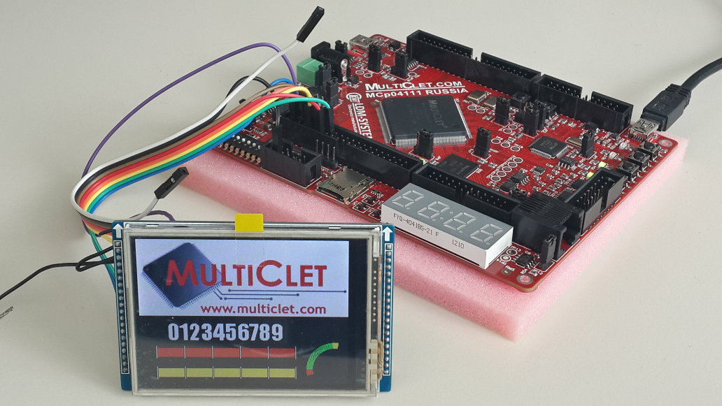
In my test program, I generated fonts and a picture in the RLE sequence using the lcd-image-converter program. True, I had to modify the algorithm for generating RLE sequences, the most optimal when working with 32-bit words. The original code produced something "inedible."
Having enclosed everything a bit with functions for drawing sectors, circles, rectangles with lines, you can get this result:

Quest one
Immediately after connecting, the system joyfully detected a paired FTDI device, creating two ttyUSBx devices at once. And here is the dilemma - either use the Serial console, or be able to upload firmware - the bundled bootloader works directly with the FTDI device. I had to draw scripts on my knee for the “correct” loading of the ftdi_sio module. Kneeling proved to be in the use of Python bindings to the ftd2xx library. The general point is to unload the module, block FTDI used for firmware, and at the same time load the module back. Then the core module can block the remaining FTDI for UART.
Hello world! - too commonplace
The simple "Hello, world!" With flashing LEDs started working immediately, it was only found that after flashing Linux mc-ploader, it was necessary to additionally reset the board or wait until WDT worked.
Once in the winter I ordered myself a pair of HY28A SPI screens , but they only arrived with our mail in May. Here, the solution itself came up - to start from the screen. Armed with the SYSCLK DX USB logic analyzer, I got to study specs on the GPIO and SPIx registers in the MCp processor and tinker with SPI examples.
Sound setting
On the LDM board, two out of three SPIs were already involved. One for the ADC, the second for the microSD slot. All MCp peripherals consist of GPIO registers, which also have alternative functions, whether it is a network interface (MAC / MDIO), UART, USB, or I2C.
First of all, it is necessary to configure an alternative function via bit fields for the remaining unused SPI0. To work, we need to connect a couple of header files:
#include
#include
…
GPIOB->BPS = 0x07F; Now we need to set the parameters of the SPI bus itself:
SPI0->SS = 0x07; // выставляем сигнал CS в логическую единицу
SPI0->CR = 0x37710000;| Bit | Value | Description |
|---|---|---|
| 29th | 1 | Polarization. SCK status in standby mode. We use the HIGH signal. |
| 28 | 1 | The phase of the clock. We read data in recession. |
| 27 | 0 | Ban divisor by 16. We want maximum speed. With a processor frequency of 80MHz, the SPI bus frequency will be 20MHz |
| 26 | 1 | The transmission bit sequence is LSB or MSB. We use MSB. |
| 25 | 1 | The operating mode of our SPI: “0” - slave, “1” - master. |
| 24 | 1 | This bit turns on the SPI block. |
| 23-20 | 0111 | Data word length. We want 8 bits (0x3 - 0xf - 4-16 bits respectively). For 32 bits, the field value must be zero. |
| 19-16 | 0001 | Sets the pre-selector mode. At zero, there were problems with the clock. T.ch. I chose "1". |
To select a slave, SS0-SS2 lines are used. Active is considered the LOW state. Sampling is carried out through the SPIxSS register: “1” sets the value HIGH, and “0” sets the value LOW.
With configuration SPI more or less figured out. Let's move on to the display.
The pinout is quite simple. We need to connect the pins 3v3_IN, GND, SCK, CS, SDO (aka MISO), SDI (aka MOSI) and nRESET with BL_CTRL. Using the BL_CTRL line and PWM, you can control the brightness of the LED backlight. The backlight is already rather weak, incl. just feed it from 3v3. The nRESET signal line is used during the screen reset / initialization procedure. To do this, we need to configure another GPIO output:
GPIOB->DIR |= 0x100; // Задаём 8-ой вывод GPIOB как OUTPUT
GPIOB->OUT &= ~0x100; // Переводим вывод в состояние LOWSPI: First Steps
In order to convey something, we must announce our intentions. To do this, before each sending of commands, we need to select the slave device. We have one thing - LCD. The command to write to the SPI port for our 8-bit packages will look like this:
#define SPI_CS_LOW  SPI0->SS = 0x06  /* объявляем макросы по выбору активной линии */
#define SPI_CS_HI   SPI0->SS = 0x07 /* … и сбросу выбора */
int SPI_WRITE(int data)
{
    /* Не забываем, что наш байт надо положить в старший байт регистра TX, т.к. у нас MSB */
    SPI0->TX = ((uint32_t)data) << 24;
    /* Ждём пока данные передаются */
    while(SPI_ST_TIP(SPI0) == 1);
    /* Ждём наличие данных */
    /* Возможно, ещё стоит проверить на заполненность буфера (SPI_ST_NF) */
    while(SPI_ST_NE(SPI0) == 0);
    /*
     * Читаем значение регистра RX.
     * Стоим напомнить, что одновременно с передачей битов происходит чтение,
     * чем мы и будем пользоваться далее.
     */
    return SPI0->RX;
}Work with the LCD comes down to issuing commands to set the position (X, Y) or limiting the scanning area, and then sequentially recorded data will fill the specified area. For example, drawing rectangles is done by sequentially writing WxHwords of color value, thereby optimizing the number of issued commands. SPI is not a fast bus; slaves can operate at frequencies up to 25 MHz. Therefore, it will not work to show the video - for this purpose it is necessary to use a parallel bus. There is no double buffer either. Everything that is issued by SPI is recorded in the internal memory of the display driver and, upon subsequent scanning, is displayed on the screen. Welcome to the days of Turbo Pascal with the graph module! T.ch. the screen in SPI mode is good for displaying statics or a rarely changing picture.
In my test program, I generated fonts and a picture in the RLE sequence using the lcd-image-converter program. True, I had to modify the algorithm for generating RLE sequences, the most optimal when working with 32-bit words. The original code produced something "inedible."
Having enclosed everything a bit with functions for drawing sectors, circles, rectangles with lines, you can get this result: