About color spaces
I am a programmer by education, but at work I had to deal with image processing. And then an amazing and unexplored world of color spaces opened up for me. I don’t think that designers and photographers will learn something new for themselves, but perhaps this knowledge will turn out to be at least useful to someone, and at best interesting.
The main task of color models is to make it possible to set colors in a unified way. In fact, color models define specific coordinate systems that allow you to uniquely determine the color.
The most popular today are the following color models: RGB (used mainly in monitors and cameras), CMY (K) (used in printing), HSI (widely used in machine vision and design). There are many other models. For example, CIE XYZ (standard models), YCbCr, etc. The following is a brief overview of these color models.
From Grassmann's law, the idea of an additive (i.e. based on a mixture of colors from directly emitting objects) color reproduction model arises. For the first time, such a model was proposed by James Maxwell in 1861, but it received the greatest distribution much later.
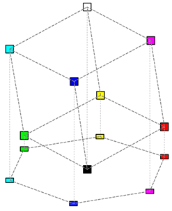
In the RGB model (from the English red - red, green - green, blue - blue), all colors are obtained by mixing three basic (red, green and blue) colors in various proportions. The share of each base color in the final one can be perceived as a coordinate in the corresponding three-dimensional space, therefore this model is often called a color cube. In Fig. 1 shows a color cube model.
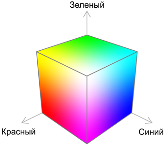
Most often, the model is built so that the cube is single. The points corresponding to the base colors are located at the vertices of the cube lying on the axes: red - (1; 0; 0), green - (0; 1; 0), blue - (0; 0; 1). In this case, the secondary colors (obtained by mixing two basic) are located at other vertices of the cube: cyan - (0; 1; 1), magenta - (1; 0; 1) and yellow - (1; 1; 0). Black and white colors are located at the origin (0; 0; 0) and at the point farthest from the origin (1; 1; 1). Fig. shows only the vertices of the cube.

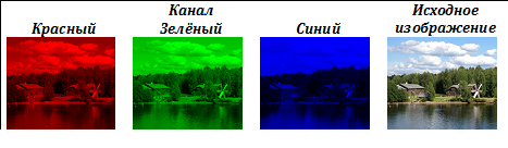
Color images in the RGB model are built from three separate image channels. In Tab. shows the decomposition of the original image into color channels.
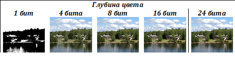
In the RGB model, a certain number of bits is allocated for each color component, for example, if 1 byte is allocated for each component, then 2 ^ (3 * 8) ≈16 million colors can be encoded using this model. In practice, such coding is redundant, because most people are unable to distinguish so many colors. Often limited to so-called High Color mode in which 5 bits are allocated for each component coding. Some applications use a 16-bit mode in which 5 bits are allocated for encoding the R and B components, and 6 bits for encoding the G component. This mode, firstly, takes into account a person’s higher sensitivity to green color, and secondly, it allows more efficient use of computer architecture features. The number of bits allocated for encoding a single pixel is called color depth. In Tab.
The subtractive model CMY (from the English cyan - cyan, magenta - magenta, yellow - yellow) is used to obtain hard copies (print) of images, and is in some way the antipode of the RGB color cube. If in the RGB model the base colors are the colors of the light sources, then the CMY model is the color absorption model.
For example, paper coated with a yellow dye does not reflect blue light, i.e. we can say that the yellow dye subtracts blue from the reflected white light. Similarly, a blue dye subtracts red from the reflected light, and a purple dye subtracts green. That is why this model is called subtractive. The conversion algorithm from the RGB model to the CMY model is very simple:
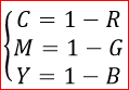
It is assumed that RGB colors are in the range [0; 1]. It is easy to see that to obtain black in the CMY model, it is necessary to mix cyan, magenta and yellow in equal proportions. This method has two serious drawbacks: firstly, the black obtained as a result of mixing will look lighter than the “real” black, and secondly, this leads to significant dye costs. Therefore, in practice, the CMY model is expanded to the CMYK model, adding black to the three colors.
The RGB and CMY (K) color models discussed earlier are quite simple in terms of hardware implementation, but they have one significant drawback. It is very difficult for a person to operate with the colors specified in these models, because a person, when describing colors, does not use the content in the described color of the basic components, but in slightly different categories.
Most often, people operate with the following concepts: color tone, saturation and lightness. At the same time, talking about the color tone, usually they mean exactly the color. Saturation indicates how much the color described is diluted with white (pink, for example, is a mixture of red and white). The concept of lightness is the most difficult to describe, and with some assumptions, lightness can be understood as light intensity.
If we consider the projection of the RGB cube in the direction of the white-black diagonal, we get a hexagon:
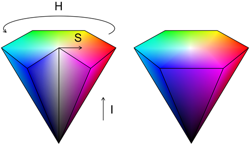
All the gray colors (lying on the diagonal of the cube) are then projected to the center point. To use this model to encode all the colors available in the RGB model, you need to add the vertical axis of lightness (or intensity) (I). The result is a hexagonal cone:
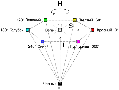
In this case, the tone (H) is set by the angle relative to the axis of red color, the saturation (S) characterizes the purity of the color (1 means absolutely pure color, and 0 corresponds to a shade of gray). It is important to understand that hue and saturation are not defined at zero intensity.
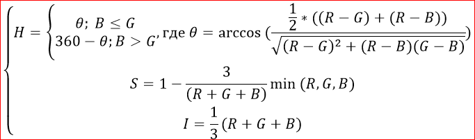
The conversion algorithm from RGB to HSI can be performed using the following formulas:
The HSI color model is very popular among designers and artists, as This system provides direct control of tone, saturation and brightness. The same properties make this model very popular in machine vision systems. In Tab. Shows the image changes with increasing and decreasing intensity, tone (rotation is performed ± 50 °) and saturation.

In order to unify, an international standard color model was developed. As a result of a series of experiments, the International Lighting Commission (CIE) determined the addition curves of the primary (red, green, and blue) colors. In this system, each visible color corresponds to a certain ratio of primary colors. At the same time, in order for the developed model to reflect all the colors visible by a person, a negative number of basic colors had to be introduced. To get away from negative values of CIE, introduced the so-called unrealistic or imaginary primary colors: X (imaginary red), Y (imaginary green), Z (imaginary blue).
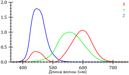
When describing the color, the values of X, Y, Z are called standard main excitations, and the coordinates obtained on their basis are called standard color coordinates. The standard addition curves X (λ), Y (λ), Z (λ) (see Fig.) Describe the sensitivity of the average observer to standard excitations:
In addition to standard color coordinates, the concept of relative color coordinates is often used, which can be calculated using the following formulas:
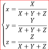
Easy note that x + y + z = 1, which means that to uniquely specify the relative coordinates, any pair of values is sufficient, and the corresponding color space can be represented in the form of a two-dimensional graph: The
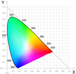
set of colors specified by this method bom, called the CIE triangle.
It is easy to notice that the CIE triangle describes only the color tone, but does not describe the brightness in any way. To describe the brightness, an additional axis is introduced, passing through a point with coordinates (1/3; 1/3) (the so-called white point). The result is the CIE color body (see. Fig.):
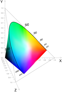
This body contains all the colors that are visible to the average observer. The main disadvantage of this system is that using it, we can only state the coincidence or difference of two colors, but the distance between two points of this color space does not correspond to the visual perception of the color difference.
The main goal in developing CIELAB was to eliminate the nonlinearity of the CIE XYZ system in terms of human perception. The acronym LAB usually refers to the CIE L * a * b * color space, which is currently the international standard.
In the CIE L * a * b system, the L coordinate means lightness (ranging from 0 to 100), and the a, b coordinates indicate the position between green-magenta and blue-yellow. The formulas for translating coordinates from CIE XYZ to CIE L * a * b * are given below:
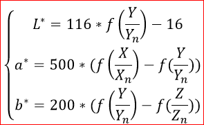
where (Xn, Yn, Zn) are the coordinates of the white point in the CIE XYZ space, and
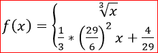
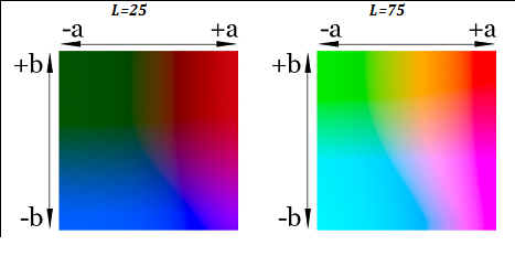
Fig. Sections of the color body CIE L * a * b * are presented for two values of lightness:
Compared to the CIE XYZ system, the Euclidean distance (√ ((L1-L2) ^ 2 + (a1 ^ * - a2 ^ *) ^ 2 + (b1 ^ * - b2 ^ *) ^ 2)) in the CIE L * system * b * matches the color difference perceived by a person much better, however, the extremely complex CIEDE2000 is the standard formula for color difference.
In the YIQ and YUV color systems, color information is represented as a luminance signal (Y) and two color difference signals (IQ and UV, respectively).
The popularity of these color systems is due primarily to the advent of color television. Because the Y component essentially contains the original image in grayscale, the signal in the YIQ system could be received and correctly displayed both on old black-and-white televisions, and on new color ones.
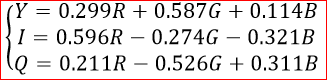
The second, perhaps more important plus, of these spaces is the separation of information about the color and brightness of the image. The fact is that the human eye is very sensitive to changes in brightness, and much less sensitive to changes in color. This allows you to transfer and store color information with reduced depth. It is on this feature of the human eye that the most popular image compression algorithms are built today (including jpeg). The following formulas can be used to translate from RGB to YIQ:
The main task of color models is to make it possible to set colors in a unified way. In fact, color models define specific coordinate systems that allow you to uniquely determine the color.
The most popular today are the following color models: RGB (used mainly in monitors and cameras), CMY (K) (used in printing), HSI (widely used in machine vision and design). There are many other models. For example, CIE XYZ (standard models), YCbCr, etc. The following is a brief overview of these color models.
RGB color cube
From Grassmann's law, the idea of an additive (i.e. based on a mixture of colors from directly emitting objects) color reproduction model arises. For the first time, such a model was proposed by James Maxwell in 1861, but it received the greatest distribution much later.
In the RGB model (from the English red - red, green - green, blue - blue), all colors are obtained by mixing three basic (red, green and blue) colors in various proportions. The share of each base color in the final one can be perceived as a coordinate in the corresponding three-dimensional space, therefore this model is often called a color cube. In Fig. 1 shows a color cube model.
Most often, the model is built so that the cube is single. The points corresponding to the base colors are located at the vertices of the cube lying on the axes: red - (1; 0; 0), green - (0; 1; 0), blue - (0; 0; 1). In this case, the secondary colors (obtained by mixing two basic) are located at other vertices of the cube: cyan - (0; 1; 1), magenta - (1; 0; 1) and yellow - (1; 1; 0). Black and white colors are located at the origin (0; 0; 0) and at the point farthest from the origin (1; 1; 1). Fig. shows only the vertices of the cube.
Color images in the RGB model are built from three separate image channels. In Tab. shows the decomposition of the original image into color channels.
In the RGB model, a certain number of bits is allocated for each color component, for example, if 1 byte is allocated for each component, then 2 ^ (3 * 8) ≈16 million colors can be encoded using this model. In practice, such coding is redundant, because most people are unable to distinguish so many colors. Often limited to so-called High Color mode in which 5 bits are allocated for each component coding. Some applications use a 16-bit mode in which 5 bits are allocated for encoding the R and B components, and 6 bits for encoding the G component. This mode, firstly, takes into account a person’s higher sensitivity to green color, and secondly, it allows more efficient use of computer architecture features. The number of bits allocated for encoding a single pixel is called color depth. In Tab.
Subtractive CMY and CMYK models
The subtractive model CMY (from the English cyan - cyan, magenta - magenta, yellow - yellow) is used to obtain hard copies (print) of images, and is in some way the antipode of the RGB color cube. If in the RGB model the base colors are the colors of the light sources, then the CMY model is the color absorption model.
For example, paper coated with a yellow dye does not reflect blue light, i.e. we can say that the yellow dye subtracts blue from the reflected white light. Similarly, a blue dye subtracts red from the reflected light, and a purple dye subtracts green. That is why this model is called subtractive. The conversion algorithm from the RGB model to the CMY model is very simple:
It is assumed that RGB colors are in the range [0; 1]. It is easy to see that to obtain black in the CMY model, it is necessary to mix cyan, magenta and yellow in equal proportions. This method has two serious drawbacks: firstly, the black obtained as a result of mixing will look lighter than the “real” black, and secondly, this leads to significant dye costs. Therefore, in practice, the CMY model is expanded to the CMYK model, adding black to the three colors.
Color Space Hue, Saturation, Intensity (HSI)
The RGB and CMY (K) color models discussed earlier are quite simple in terms of hardware implementation, but they have one significant drawback. It is very difficult for a person to operate with the colors specified in these models, because a person, when describing colors, does not use the content in the described color of the basic components, but in slightly different categories.
Most often, people operate with the following concepts: color tone, saturation and lightness. At the same time, talking about the color tone, usually they mean exactly the color. Saturation indicates how much the color described is diluted with white (pink, for example, is a mixture of red and white). The concept of lightness is the most difficult to describe, and with some assumptions, lightness can be understood as light intensity.
If we consider the projection of the RGB cube in the direction of the white-black diagonal, we get a hexagon:
All the gray colors (lying on the diagonal of the cube) are then projected to the center point. To use this model to encode all the colors available in the RGB model, you need to add the vertical axis of lightness (or intensity) (I). The result is a hexagonal cone:
In this case, the tone (H) is set by the angle relative to the axis of red color, the saturation (S) characterizes the purity of the color (1 means absolutely pure color, and 0 corresponds to a shade of gray). It is important to understand that hue and saturation are not defined at zero intensity.
The conversion algorithm from RGB to HSI can be performed using the following formulas:
The HSI color model is very popular among designers and artists, as This system provides direct control of tone, saturation and brightness. The same properties make this model very popular in machine vision systems. In Tab. Shows the image changes with increasing and decreasing intensity, tone (rotation is performed ± 50 °) and saturation.
Model CIE XYZ
In order to unify, an international standard color model was developed. As a result of a series of experiments, the International Lighting Commission (CIE) determined the addition curves of the primary (red, green, and blue) colors. In this system, each visible color corresponds to a certain ratio of primary colors. At the same time, in order for the developed model to reflect all the colors visible by a person, a negative number of basic colors had to be introduced. To get away from negative values of CIE, introduced the so-called unrealistic or imaginary primary colors: X (imaginary red), Y (imaginary green), Z (imaginary blue).
When describing the color, the values of X, Y, Z are called standard main excitations, and the coordinates obtained on their basis are called standard color coordinates. The standard addition curves X (λ), Y (λ), Z (λ) (see Fig.) Describe the sensitivity of the average observer to standard excitations:
In addition to standard color coordinates, the concept of relative color coordinates is often used, which can be calculated using the following formulas:
Easy note that x + y + z = 1, which means that to uniquely specify the relative coordinates, any pair of values is sufficient, and the corresponding color space can be represented in the form of a two-dimensional graph: The
set of colors specified by this method bom, called the CIE triangle.
It is easy to notice that the CIE triangle describes only the color tone, but does not describe the brightness in any way. To describe the brightness, an additional axis is introduced, passing through a point with coordinates (1/3; 1/3) (the so-called white point). The result is the CIE color body (see. Fig.):
This body contains all the colors that are visible to the average observer. The main disadvantage of this system is that using it, we can only state the coincidence or difference of two colors, but the distance between two points of this color space does not correspond to the visual perception of the color difference.
Model CIELAB
The main goal in developing CIELAB was to eliminate the nonlinearity of the CIE XYZ system in terms of human perception. The acronym LAB usually refers to the CIE L * a * b * color space, which is currently the international standard.
In the CIE L * a * b system, the L coordinate means lightness (ranging from 0 to 100), and the a, b coordinates indicate the position between green-magenta and blue-yellow. The formulas for translating coordinates from CIE XYZ to CIE L * a * b * are given below:
where (Xn, Yn, Zn) are the coordinates of the white point in the CIE XYZ space, and
Fig. Sections of the color body CIE L * a * b * are presented for two values of lightness:
Compared to the CIE XYZ system, the Euclidean distance (√ ((L1-L2) ^ 2 + (a1 ^ * - a2 ^ *) ^ 2 + (b1 ^ * - b2 ^ *) ^ 2)) in the CIE L * system * b * matches the color difference perceived by a person much better, however, the extremely complex CIEDE2000 is the standard formula for color difference.
TV color difference color systems
In the YIQ and YUV color systems, color information is represented as a luminance signal (Y) and two color difference signals (IQ and UV, respectively).
The popularity of these color systems is due primarily to the advent of color television. Because the Y component essentially contains the original image in grayscale, the signal in the YIQ system could be received and correctly displayed both on old black-and-white televisions, and on new color ones.
The second, perhaps more important plus, of these spaces is the separation of information about the color and brightness of the image. The fact is that the human eye is very sensitive to changes in brightness, and much less sensitive to changes in color. This allows you to transfer and store color information with reduced depth. It is on this feature of the human eye that the most popular image compression algorithms are built today (including jpeg). The following formulas can be used to translate from RGB to YIQ: