Scalable networks in Openstack. Part 2: VlanManager
Author: Piotr Siwczak
In the first part of the article I described the main mode of network operation in OpenStack, in particular, the network manager FlatManager and its addition, FlatDHCPManager. In this article I will talk about VlanManager. While flat-mode managers are designed for simple and small deployments, VlanManager is suitable for large internal clouds and public clouds. As the name suggests, VlanManager relies on the use of virtual local area networks (“virtual LANs”). The purpose of virtual LANs is to divide the physical network into separate broadcast domains (so that groups of nodes in different virtual networks do not see each other). VlanManager is trying to fix two main drawbacks of network managers, namely:
-Lack of scalability (managers working in flat mode rely on a single L2 broadcast domain for all OpenStack installations)
-Lack of user isolation (a single pool of IP addresses that is used by all users)
In this article, I focus on VlanManager, which uses network mode with multiple nodes in OpenStack. Outside the sandbox, this is safer than single-node mode, since multi-node mode does not suffer from a single failure resulting from the operation of a separate instance of the nova-network service on the entire openstack cluster. However, it is possible to use VlanManager in single-node mode. (You can read more about the correlation of the “multi-node” and “single-node” modes here ).
When working with managers in flat mode during the network setup process, the administrator usually performs the following actions:
-Creates one large network with fixed IP addresses (usually with a network mask of 16 or less bits), which is shared by all users:
-Creates users
-After of how users create their instances, assigns each a free IP address from a common pool of IP addresses.
Typically, in this mode, instances are allocated to IP addresses as follows:
tenant_1:

tenant_2:

We see that instances tenant_1 and tenant_2 are on the same IP network, 10.0.0.0.
If using VlanManager, the administrator acts as follows:
-Creates a new user, writes tenantID
-Creates a dedicated fixed ip-network for a new user: -After creating a user instance, an IP address from a private pool of IP addresses will be automatically assigned. Thus, in comparison with FlatDHCPManager, we additionally define two things for the network: -Network connection with a specific user (--project_id =). Thus, IP addresses from the network cannot be taken by anyone except the user. - Allocation of a separate virtual network for this network (--vlan = 102).
From this moment, as soon as the user creates a new virtual machine, it automatically receives the IP address from the allocated pool. It is also placed on a dedicated vlan virtual network, which is automatically created and supported by the OpenStack platform. Thus, if we created two different networks for two users, the situation is as follows:
tenant_1:

tenant2: It is

clearly seen that user instances are in different pools of IP addresses. But how are virtual networks supported?
VlanManager does three things here:
-Creates a dedicated bridge for the user's network on the compute node.
-Creates a vlan interface on top of the physical network interface eth0 of the compute node.
- Starts and configures the dnsmasq process corresponding to the bridge so that the user instance can be loaded from it.
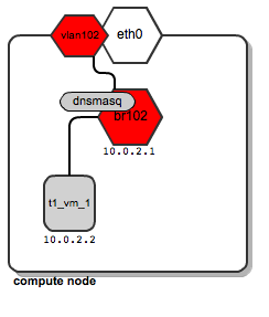
Let's assume that a user called “t1” creates his instance of t1_vm_1 . It hits one of the computing nodes. This is what the network diagram looks like:

We see that a dedicated “br102” bridge with a vlan interface called “vlan102” was created. In addition, a dnsmasq process has been created that listens on the address 10.0.2.1. When an instance of instance t1_vm_1 is loaded, it receives its address from the dnsmasq process based on a static lease (for details on how dnsmasq is managed by the OpenStack platform, see the previous article ).
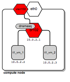
Now, let's assume that user “t1” creates another instance called t1_vm_2 , and he accidentally ends up on the same compute node as the previous created instance:

Both instances are connected to the same bridge, as they belong to the same user, and thus they are in the same dedicated network users. In addition, they receive their DHCP configuration from a single dnsmasq server.
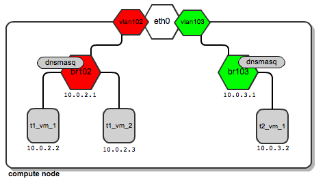
Now, imagine that the user “t2” creates his first instance . It also ends up on the same computing node as user “t1”. In addition, a dedicated bridge, vlan interface, and dnsmasq process are configured for its network:

Thus, it turns out that depending on the number of users, it is quite normal for you to have a sufficiently large number of network bridges and dnsmasq processes, and all work on the same computing node.
There is nothing strange in this situation - OpenStack will automatically manage all of them. In contrast to the use of managers in flat mode, here both instances of users are located on different bridges that are not connected to each other. This will provide traffic separation at the L2 level. In the case of the “t1” user, ARP broadcasts transmitted on br102 and then on vlan102 are not visible on br103 and vlan103, and vice versa.
Above, we talked about how this works on a single computing node. Most likely you will use several computing nodes. Usually we strive for the greatest number of computing nodes. Then, most likely, the user “t1 ″ will be distributed among several computing nodes. This means that a dedicated network must also be distributed between several computing nodes. However, it must satisfy two requirements:
- Communication of instances of t1, which are located on different physical computer nodes
, must be ensured; -The network t1, distributed across several computing nodes, must be isolated from other user networks.
Typically, compute nodes are connected to the network with a single cable. We would like several users to share this channel without seeing each other's traffic.
There is a technology that satisfies this requirement - Vlan tagging (802.1q). Technically, each Ethernet frame is supplemented by a 12-bit field called VID (Vlan ID), which has a vlan number. Frames that have the same Vlan tag belong to the same L2 translation domain; thus, devices with traffic tagged with the same Vlan ID can communicate.
Therefore, it is clear that you can isolate user networks by tagging them with different Vlan IDs.
How does it work in practice? Take a look at the diagrams above.
Traffic for the user “t1” leaves the compute node via the interface “vlan102 ″. Vlan102 is a virtual interface connected to eth0. Its sole purpose is to tag frames with the number “102 ″ using the 802.1q protocol.
Traffic for the user “t2” leaves the compute node via the interface “vlan103 ″, which is tagged with 103. Since the stream has different vlan tags, the traffic“ t1′s ”does not intersect with the traffic“ t2 '.
They have no idea about each other, although they both use the same physical interface eth0, and then the ports and trunk of the switch.
Then we need to tell the switch that the tagged traffic needs to be transmitted on its ports. This is achieved by putting this switch port in trunk mode (as opposed to the default “access” mode). In short, the trunk allows the switch to transmit frames tagged with VLANs; For more information on vlan trunks, see this article (802.1q). At this time, the switch is configured by the system administrator . Openstack does not perform this configuration on its own. Not all switches support vlan trunking. This must be checked before purchasing the switch.
Also, if you use devstack + virtualboxFor experimenting with VlanManager in a virtual environment, make sure you select “PCNET - Fast III” as the adapter for connecting to your VLAN.
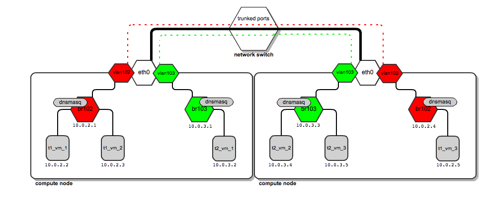
Having done this, we come to the following communication model: The

thick black line from the computing nodes to the switch is a physical channel (cable). Vlan traffic with tags 102 and 103 (red and green dashed lines) is transferred over the same cable. Traffic does not mix (two lines never intersect).
What does the traffic look like when the user “t1” wants to send a packet from 10.0.2.2 to 10.0.2.5?
-Package goes from 10.0.2.2 to the br102 bridge and up to vlan102, where tag 102 is assigned to it.
-Traffic passes behind a switch that processes vlan tags. Once it reaches the second compute node, its vlan tag is examined.
-Based on the results of the study, the computing node decides to send it to the vlan102 interface.
-Vlan102 removes the Vlan ID field from the packet so that the packet can reach instances (instances do not have a tagged interface).
-Then it goes through br102 and reaches the address 10.0.2.5.
Configuring VlanManager
To configure the VlanManager network settings in OpenStack, put the following lines in the nova.conf file:
#We point OpenStack to use VlanManager here:
network_manager = nova.network.manager.VlanManager
#Interface on which virtual vlan interfaces will be created:
vlan_interface = eth0
#The first tag number for private vlans
# (in this case, vlan numbers lower than 100 can serve our
#internal purposes and will not be consumed by tenants):
vlan_start = 100
In any case, VlanManager is the most sophisticated networking model that is currently offered by OpenStack. L2 scalability and traffic isolation for different users are provided.
However, this manager has its limitations. For example, for each user network, it assigns IP pools (L3 level) to vlan networks (L2 level) (remember? Each user's network is determined by a pair of ip + vlan pools). Thus, it is impossible to make two different users use the same IP addressing scheme independently in different L2 domains.
In addition, the vlan tag field is only 12 bits long, which allows a maximum of 4096 vlan to be created. This means that you can have no more than 4096 potential users, not so many in the cloud.
These limitations will still be circumvented by emerging solutions such as Quantum , the new network manager for the OpenStack platform and software-defined networking .
In the next article in this series, I will explain how floating ip addresses work.
Original article in English
In the first part of the article I described the main mode of network operation in OpenStack, in particular, the network manager FlatManager and its addition, FlatDHCPManager. In this article I will talk about VlanManager. While flat-mode managers are designed for simple and small deployments, VlanManager is suitable for large internal clouds and public clouds. As the name suggests, VlanManager relies on the use of virtual local area networks (“virtual LANs”). The purpose of virtual LANs is to divide the physical network into separate broadcast domains (so that groups of nodes in different virtual networks do not see each other). VlanManager is trying to fix two main drawbacks of network managers, namely:
-Lack of scalability (managers working in flat mode rely on a single L2 broadcast domain for all OpenStack installations)
-Lack of user isolation (a single pool of IP addresses that is used by all users)
In this article, I focus on VlanManager, which uses network mode with multiple nodes in OpenStack. Outside the sandbox, this is safer than single-node mode, since multi-node mode does not suffer from a single failure resulting from the operation of a separate instance of the nova-network service on the entire openstack cluster. However, it is possible to use VlanManager in single-node mode. (You can read more about the correlation of the “multi-node” and “single-node” modes here ).
Differences between managers working in “flat” mode and VlanManager
When working with managers in flat mode during the network setup process, the administrator usually performs the following actions:
-Creates one large network with fixed IP addresses (usually with a network mask of 16 or less bits), which is shared by all users:
nova-manage network create --fixed_range_v4=10.0.0.0/16 --label=public-Creates users
-After of how users create their instances, assigns each a free IP address from a common pool of IP addresses.
Typically, in this mode, instances are allocated to IP addresses as follows:
tenant_1:

tenant_2:

We see that instances tenant_1 and tenant_2 are on the same IP network, 10.0.0.0.
If using VlanManager, the administrator acts as follows:
-Creates a new user, writes tenantID
-Creates a dedicated fixed ip-network for a new user: -After creating a user instance, an IP address from a private pool of IP addresses will be automatically assigned. Thus, in comparison with FlatDHCPManager, we additionally define two things for the network: -Network connection with a specific user (--project_id =). Thus, IP addresses from the network cannot be taken by anyone except the user. - Allocation of a separate virtual network for this network (--vlan = 102).
nova-manage network create --fixed_range_v4=10.0.1.0/24 --vlan=102 \

 --project_id="tenantID"
From this moment, as soon as the user creates a new virtual machine, it automatically receives the IP address from the allocated pool. It is also placed on a dedicated vlan virtual network, which is automatically created and supported by the OpenStack platform. Thus, if we created two different networks for two users, the situation is as follows:
tenant_1:

tenant2: It is

clearly seen that user instances are in different pools of IP addresses. But how are virtual networks supported?
How VlanManager configures network settings
VlanManager does three things here:
-Creates a dedicated bridge for the user's network on the compute node.
-Creates a vlan interface on top of the physical network interface eth0 of the compute node.
- Starts and configures the dnsmasq process corresponding to the bridge so that the user instance can be loaded from it.
Let's assume that a user called “t1” creates his instance of t1_vm_1 . It hits one of the computing nodes. This is what the network diagram looks like:

We see that a dedicated “br102” bridge with a vlan interface called “vlan102” was created. In addition, a dnsmasq process has been created that listens on the address 10.0.2.1. When an instance of instance t1_vm_1 is loaded, it receives its address from the dnsmasq process based on a static lease (for details on how dnsmasq is managed by the OpenStack platform, see the previous article ).
Now, let's assume that user “t1” creates another instance called t1_vm_2 , and he accidentally ends up on the same compute node as the previous created instance:

Both instances are connected to the same bridge, as they belong to the same user, and thus they are in the same dedicated network users. In addition, they receive their DHCP configuration from a single dnsmasq server.
Now, imagine that the user “t2” creates his first instance . It also ends up on the same computing node as user “t1”. In addition, a dedicated bridge, vlan interface, and dnsmasq process are configured for its network:

Thus, it turns out that depending on the number of users, it is quite normal for you to have a sufficiently large number of network bridges and dnsmasq processes, and all work on the same computing node.
There is nothing strange in this situation - OpenStack will automatically manage all of them. In contrast to the use of managers in flat mode, here both instances of users are located on different bridges that are not connected to each other. This will provide traffic separation at the L2 level. In the case of the “t1” user, ARP broadcasts transmitted on br102 and then on vlan102 are not visible on br103 and vlan103, and vice versa.
Support for user networks across multiple compute nodes
Above, we talked about how this works on a single computing node. Most likely you will use several computing nodes. Usually we strive for the greatest number of computing nodes. Then, most likely, the user “t1 ″ will be distributed among several computing nodes. This means that a dedicated network must also be distributed between several computing nodes. However, it must satisfy two requirements:
- Communication of instances of t1, which are located on different physical computer nodes
, must be ensured; -The network t1, distributed across several computing nodes, must be isolated from other user networks.
Typically, compute nodes are connected to the network with a single cable. We would like several users to share this channel without seeing each other's traffic.
There is a technology that satisfies this requirement - Vlan tagging (802.1q). Technically, each Ethernet frame is supplemented by a 12-bit field called VID (Vlan ID), which has a vlan number. Frames that have the same Vlan tag belong to the same L2 translation domain; thus, devices with traffic tagged with the same Vlan ID can communicate.
Therefore, it is clear that you can isolate user networks by tagging them with different Vlan IDs.
How does it work in practice? Take a look at the diagrams above.
Traffic for the user “t1” leaves the compute node via the interface “vlan102 ″. Vlan102 is a virtual interface connected to eth0. Its sole purpose is to tag frames with the number “102 ″ using the 802.1q protocol.
Traffic for the user “t2” leaves the compute node via the interface “vlan103 ″, which is tagged with 103. Since the stream has different vlan tags, the traffic“ t1′s ”does not intersect with the traffic“ t2 '.
They have no idea about each other, although they both use the same physical interface eth0, and then the ports and trunk of the switch.
Then we need to tell the switch that the tagged traffic needs to be transmitted on its ports. This is achieved by putting this switch port in trunk mode (as opposed to the default “access” mode). In short, the trunk allows the switch to transmit frames tagged with VLANs; For more information on vlan trunks, see this article (802.1q). At this time, the switch is configured by the system administrator . Openstack does not perform this configuration on its own. Not all switches support vlan trunking. This must be checked before purchasing the switch.
Also, if you use devstack + virtualboxFor experimenting with VlanManager in a virtual environment, make sure you select “PCNET - Fast III” as the adapter for connecting to your VLAN.
Having done this, we come to the following communication model: The

thick black line from the computing nodes to the switch is a physical channel (cable). Vlan traffic with tags 102 and 103 (red and green dashed lines) is transferred over the same cable. Traffic does not mix (two lines never intersect).
What does the traffic look like when the user “t1” wants to send a packet from 10.0.2.2 to 10.0.2.5?
-Package goes from 10.0.2.2 to the br102 bridge and up to vlan102, where tag 102 is assigned to it.
-Traffic passes behind a switch that processes vlan tags. Once it reaches the second compute node, its vlan tag is examined.
-Based on the results of the study, the computing node decides to send it to the vlan102 interface.
-Vlan102 removes the Vlan ID field from the packet so that the packet can reach instances (instances do not have a tagged interface).
-Then it goes through br102 and reaches the address 10.0.2.5.
Configuring VlanManager
To configure the VlanManager network settings in OpenStack, put the following lines in the nova.conf file:
#We point OpenStack to use VlanManager here:
network_manager = nova.network.manager.VlanManager
#Interface on which virtual vlan interfaces will be created:
vlan_interface = eth0
#The first tag number for private vlans
# (in this case, vlan numbers lower than 100 can serve our
#internal purposes and will not be consumed by tenants):
vlan_start = 100
Conclusion
In any case, VlanManager is the most sophisticated networking model that is currently offered by OpenStack. L2 scalability and traffic isolation for different users are provided.
However, this manager has its limitations. For example, for each user network, it assigns IP pools (L3 level) to vlan networks (L2 level) (remember? Each user's network is determined by a pair of ip + vlan pools). Thus, it is impossible to make two different users use the same IP addressing scheme independently in different L2 domains.
In addition, the vlan tag field is only 12 bits long, which allows a maximum of 4096 vlan to be created. This means that you can have no more than 4096 potential users, not so many in the cloud.
These limitations will still be circumvented by emerging solutions such as Quantum , the new network manager for the OpenStack platform and software-defined networking .
In the next article in this series, I will explain how floating ip addresses work.
Original article in English
