Cutting into two equal parts, the second part of the second part
The first part
The first part of the second part The
May holidays continue, the number of uses of the word "part" goes off the line of text, and we, dear readers, will finally finish off the case of turning with the center inside the figure.
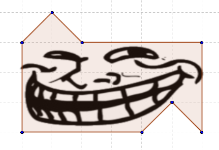
First, we use the property of the far boundary section. If this sentence is a meaningless set of letters for you, you should familiarize yourself with the previous two parts. If not, then here is a beautiful color picture, which is, in fact, a continuation of a similar picture from the previous part. Let me remind you: each of the colored areas is the geometrical place of the points for which, if they were the center of rotation, the boundary section would consist of a single vertex painted with the corresponding color. Since the cross section cannot consist of a single point (see Lemma 1), the center of rotation can be located only on the boundary between the regions. Thus, the set of possible positions of the center of rotation narrows to a set of segments. Next, we will try to narrow it to an empty set.

Due to the lack of an internal border (and the criterion associated with it), we cannot deal with this case as famously as with the case of a center outside the figure. However, we can still do something. Let's start with the following reasoning: take a secant of a slightly smaller radius than the outer boundary. Then the cross section (at least in the case of this particular figure) will consist of two or more small-small arcs. Since their angular measure will be less than the angle of rotation, when displayed from B to C, there is nothing left for them but to switch to each other. Accordingly, if we have exactly two small arcs, it means that these arcs must have equal angular measure. We show that in the case of our figure, this criterion is systematically violated.
Take an arbitrary point O on the segment i and designate it as the center. Draw a secant with a slightly smaller radius than the outer boundary. Then the section will consist of two rather small arcs: LP and QS. In this case, QS = QR + RS. However, LP = QR by virtue of symmetry. Therefore, LP ≠ QS, and therefore, the point O cannot be the center of rotation.

We can crank out a similar focus with segments j, k, m, p. For the purposes of at least some intelligibility, I removed everything superfluous from the drawing, but all the same, not a damn thing, since, as mentioned above, the arcs are very, very small. The dotted arcs are obviously parts of the secants; in bold, in fact, sections are highlighted. Dotted line segments are those tricky line segments that, similarly to the case of line i, separate a piece equal to the other line from one of the section arcs, thereby showing that the entire first arc will be larger than the second.

There remains a segment n for which it is not so convenient to show the inequality of small arcs. In view of this, we need to slightly expand the existing mathematical apparatus by adding the following lemma to it:
Lemma 3. For each point of the figure A, its image or prototype also belongs to the figure A.
What does this lemma give us? And the fact that it is sufficient to find a point that belongs to our figure, but when you turn on the appropriate angle and counterclockwise ceases to belong to it. Such a finding would mean that this turn is not good.
For these dirty goals, we take the point K. If we move the center of rotation O along the segment n, then the images of the point K when turning the plus or minus angle POQ will move along the corresponding bold arcs of the corresponding dashed circles (here it is useful to clarify that the points P and Q is the boundary section for the center lying on the segment n, and, accordingly, the angle POQ is just the angle of rotation). It is easy to see that these arcs never intersect with the figure A 0 . Therefore, the center of rotation cannot be located on the segment n.
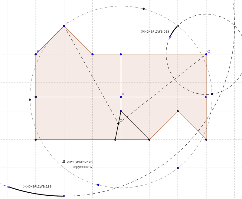
Also pay attention to the dashed-dotted circle on which the point P is located and five more nameless points are marked (the end of the “thick arc times” does not count, it got there by accident). The fact is that the point X, which is located in the center of the figure, is special. For her, the boundary section will not consist of two, but already of four points - respectively, the proof based on "small arcs" does not work for her. However, the proof based on Lemma 3 works wonderfully. The five unnamed points on the dashed-dotted circle are the images of the point P for all possible rotations corresponding to the boundary section corresponding to the point X (I apologize for misusing the word “corresponding”). None of these images fall into the figure A 0 - therefore, the point X is also excluded.
There is another special point with a special boundary section. I give attentive readers the right to find her and prove that she also cannot be the center of the turn. It is not difficult.
If the figure A 0 can be cut into two equal figures B and C, then B does not translate into C either by parallel transfer or by rotation. All that remains is sliding symmetry. The last article of the series, in which I will analyze this case, will be published on May 9, which would symbolize the final victory over a task that has done so much rustle in its time.
The first part of the second part The
May holidays continue, the number of uses of the word "part" goes off the line of text, and we, dear readers, will finally finish off the case of turning with the center inside the figure.
Case 2.2: the center of rotation inside the figure
First, we use the property of the far boundary section. If this sentence is a meaningless set of letters for you, you should familiarize yourself with the previous two parts. If not, then here is a beautiful color picture, which is, in fact, a continuation of a similar picture from the previous part. Let me remind you: each of the colored areas is the geometrical place of the points for which, if they were the center of rotation, the boundary section would consist of a single vertex painted with the corresponding color. Since the cross section cannot consist of a single point (see Lemma 1), the center of rotation can be located only on the boundary between the regions. Thus, the set of possible positions of the center of rotation narrows to a set of segments. Next, we will try to narrow it to an empty set.
Due to the lack of an internal border (and the criterion associated with it), we cannot deal with this case as famously as with the case of a center outside the figure. However, we can still do something. Let's start with the following reasoning: take a secant of a slightly smaller radius than the outer boundary. Then the cross section (at least in the case of this particular figure) will consist of two or more small-small arcs. Since their angular measure will be less than the angle of rotation, when displayed from B to C, there is nothing left for them but to switch to each other. Accordingly, if we have exactly two small arcs, it means that these arcs must have equal angular measure. We show that in the case of our figure, this criterion is systematically violated.
Take an arbitrary point O on the segment i and designate it as the center. Draw a secant with a slightly smaller radius than the outer boundary. Then the section will consist of two rather small arcs: LP and QS. In this case, QS = QR + RS. However, LP = QR by virtue of symmetry. Therefore, LP ≠ QS, and therefore, the point O cannot be the center of rotation.
We can crank out a similar focus with segments j, k, m, p. For the purposes of at least some intelligibility, I removed everything superfluous from the drawing, but all the same, not a damn thing, since, as mentioned above, the arcs are very, very small. The dotted arcs are obviously parts of the secants; in bold, in fact, sections are highlighted. Dotted line segments are those tricky line segments that, similarly to the case of line i, separate a piece equal to the other line from one of the section arcs, thereby showing that the entire first arc will be larger than the second.
There remains a segment n for which it is not so convenient to show the inequality of small arcs. In view of this, we need to slightly expand the existing mathematical apparatus by adding the following lemma to it:
Lemma 3. For each point of the figure A, its image or prototype also belongs to the figure A.
Proof: Obvious. Let the point belong to figure B, then its image belongs to figure C and, therefore, figure A. Similarly, if the point belongs to figure C.
What does this lemma give us? And the fact that it is sufficient to find a point that belongs to our figure, but when you turn on the appropriate angle and counterclockwise ceases to belong to it. Such a finding would mean that this turn is not good.
For these dirty goals, we take the point K. If we move the center of rotation O along the segment n, then the images of the point K when turning the plus or minus angle POQ will move along the corresponding bold arcs of the corresponding dashed circles (here it is useful to clarify that the points P and Q is the boundary section for the center lying on the segment n, and, accordingly, the angle POQ is just the angle of rotation). It is easy to see that these arcs never intersect with the figure A 0 . Therefore, the center of rotation cannot be located on the segment n.
Also pay attention to the dashed-dotted circle on which the point P is located and five more nameless points are marked (the end of the “thick arc times” does not count, it got there by accident). The fact is that the point X, which is located in the center of the figure, is special. For her, the boundary section will not consist of two, but already of four points - respectively, the proof based on "small arcs" does not work for her. However, the proof based on Lemma 3 works wonderfully. The five unnamed points on the dashed-dotted circle are the images of the point P for all possible rotations corresponding to the boundary section corresponding to the point X (I apologize for misusing the word “corresponding”). None of these images fall into the figure A 0 - therefore, the point X is also excluded.
There is another special point with a special boundary section. I give attentive readers the right to find her and prove that she also cannot be the center of the turn. It is not difficult.
Conclusion
If the figure A 0 can be cut into two equal figures B and C, then B does not translate into C either by parallel transfer or by rotation. All that remains is sliding symmetry. The last article of the series, in which I will analyze this case, will be published on May 9, which would symbolize the final victory over a task that has done so much rustle in its time.