Dangerous Entertainment: A Simple Cockcroft-Walton High Voltage Generator

Good afternoon, dear Khabrovites.
This post will be small and not very educational, but it may be interesting to someone. In it, I will tell you how to make a very small, completely SMD-capable and easily scalable Cockcroft-Walton generator , or simply a voltage multiplier, which receives N volt variables at the input and produces x * N volt constants at the output, where x is the number steps.
I warn you: since there are capacitors at the output (actually, like at the input, there is nothing except for capacitors and diodes in it), the current shock will most likely prove fatal for you . Assemble the scheme at your own risk and only if you understand what you are doing. I do not bear any responsibility for your life, health and psyche.
Not afraid? Then move on.
Background and Background
Actually, the background is very simple - this high-voltage generator is one of the simplest circuitry, does not contain huge coils, unlike the Tesla Transformer, and is very easy to assemble. The results, of course, are also less impressive than those of Tesla - at the output we have not a high voltage of a high frequency, but simply a high voltage. Therefore, firstly, you can’t wait for beautiful corona discharges, and secondly, unlike Tesla, the discharge of the Cockcroft-Walton generator is devoid of skin effect, therefore, it is most likely fatal. Great care should be taken.
In general, once I assembled a multiplier for myself according to the traditional scheme (we will consider a bit later), from large capacitors and diodes, which looked like this:
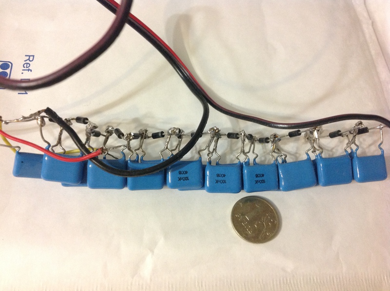
It had 15 steps, capacitors at 400V x 0.1uF and diodes at 1000V x 1A. In order to power it, I assembled a small inverter from a 220V-> 6V transformer lying around at hand, which, judging by the spark, gave out more kilovolts at the output, due to which the diodes were constantly flying out (the capacitors turned out to be more tenacious, but occasionally died and they are).
The spark at the exit was about 5 mm, it easily pierced the paper and sounded like a shot from a pistol with pistols (I think many had this in childhood ...).
To achieve more impressive results, it was necessary to increase the number of steps, which, with this design, I did not want to do at all - the sausage made of capacitors was already too large. In general, having fun with punching pieces of paper, I abandoned my multiplier.
But after a couple of years I saw in the smd.ru store just amazing, in my opinion, capacitors. Those who work with people like my friend Aregus every day , they, of course, were not new. But for me, an SMD capacitor rated at 1000V and 0.1uF, after a hefty 400V conder from my old multiplier, seemed like a miracle. Therefore, I could not restrain myself and spread a small multiplier board.
If you watch a video on youtube for the Cockcroft – Walton generator , you can find, of course, much more spectacular results with a multi-voltage output. However, they are all assembled on hefty condors for installation in holes and, most often, just hang in the air just like my first generator. I bred my board so that it was:
1) small sizes
2) fully SMD
3) easily scalable.
The result was a board measuring 35x45 mm, with mounts in the corners under a standard rack. There are 10 steps on the board, the maximum input voltage is up to 500V. The board can withstand more, but then the diodes periodically die. If we take the breakdown voltage of air at 30 KV / cm, then the maximum that it gave out is several discharges of 10-15 KV, after which one of the diodes was knocked out. When working in the nominal mode, this, of course, does not happen - it can be powered, for example, from 220V, having received about 3111V at the output without damage to its components. And, most importantly - you can easily make a dozen of these boards, make a tower of them using racks, and get a multiplier of 100 times.
Consider the circuitry of the board.
Iron
Circuit board is very simple.

This is a typical scheme of the Cockcroft-Walton generator, a voltage multiplier that is well described on Wikipedia.
The mechanism of its operation is also described there:
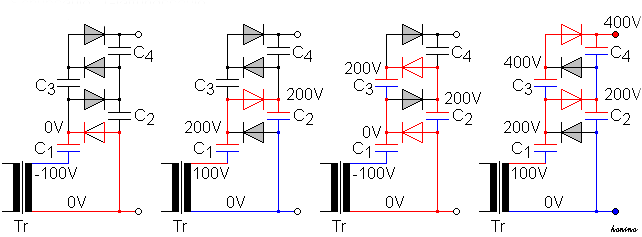
Thanks to the diodes, the capacitors are charged in turn to double the supply voltage, respectively, at the output we have a voltage increased by N times, where N is the number of capacitors in the circuit. Of course, capacitors should be selected so that they withstand this double voltage, therefore, because capacitors in the circuit are designed for 1000V, the maximum that you can apply to them without fear of failure is 500V. For an even count, I took 10 steps.
Next, I spread the board:

Top side
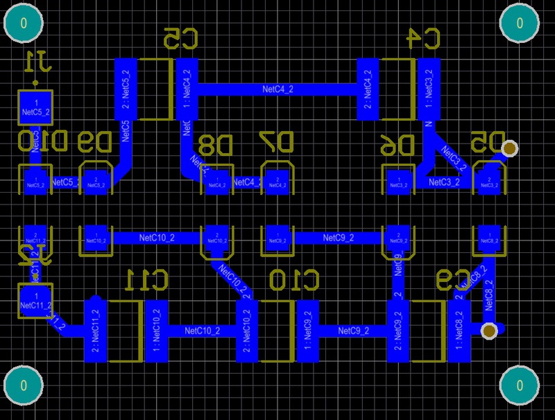
bottom side
It was possible, in principle, to reduce the size even more, but I decided not to grind it so that it would not inadvertently break through where it was not necessary.
The tracks were specially made thicker, because the lack of space by virtue of the previous paragraph did not experience. In general, it is easy to make a board with LUT or the photoresistive method at home.
But since I still needed to order several boards for work, I placed three modules of the multiplier on the same workpiece, since they almost did not take up space.
results
As a result, such a wonderful board came to me from production:

In the already mentioned store, I bought 10 capacitors and 10 diodes (actually a few more, with a margin, and for good reason - I still could not resist and powered the multiplier from my inverter, voltage the output of which is clearly higher than that for which capacitors and diodes are designed, as a result of which the input diode is knocked out after three or four discharges).

After assembly, we get such a module:
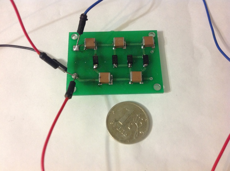
It is surrounded by my old inverter shown in the very first photo of the article.
For a long time I did not dare to connect it to 220 volts - apparently, it affected that I was a digital camera and never once had a high voltage.
I really did not want to shoot myself from the generator, which he himself had assembled, on the day of his twenty-fifth birthday. But in the end, I still overpowered myself and powered the module from the outlet, turning on in series with the kettle, which acted as current-limiting resistance - with a kettle power of 1 kW, the maximum current that would flow, in the case of a short circuit in the circuit, would be no more than 4.5 A.
Fortunately, the scheme worked the first time because of its simplicity.
Below is a video of work. Unfortunately, my camera cannot capture normally short, but bright discharges and normally capture the accompanying sound. But, if you look in HD, you can clearly see how the discharges pierce through a piece of paper.
For those who do not want to watch video in HD for this - a photo of a broken piece of paper (broken many times in the upper right corner):

By the way, the video is probably imperceptible, but it’s clearly visible in the live video that when a piece of paper is inserted between the electrodes, the spark acquires a reddish hue - apparently due to burning out substance.
In general, capacitors and diodes cost me 200-300 rubles (15 pieces of both), now I don’t remember exactly, but they don’t write the price on the site.
The production of the board cost me 2,600 rubles in Moscow Resonite . But it should be remembered that, firstly, there were six boards in the order, only three of which were multiplier boards. The total size of the workpiece was about 100x200 mm.
And secondly, out of these 2,600 rubles, 1800 cost preparation for production and 350 cost delivery, so the boards themselves came out very cheaply. I think there will be many who disagree, but at this price for boards, I just don’t have a chance to tinker with their manufacture at home - now I prefer to work to the maximum on breadboards, accumulate several different boards, and then order them all at once.
In future plans to order the same dozen of these boards and assemble a tower for 30+ kilovolts.
That's all for me, take care and be careful with high voltage.