Developing a WP8 Game Using Netduino
- Transfer
We came across an interesting article from a Windows Phone application developer and decided to share it with you.
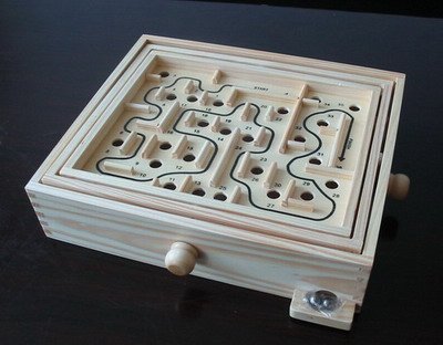
When I was a kid, my parents gave me a wooden maze game. I really liked her. I do not think that the labyrinth itself ever worried me, but the tilt mechanism was intriguing and very simple.
Later, I remembered this game and decided to find this game online and my old maze in the pantry.
Now there are a lot of similar games using the phone’s accelerometer, but their graphics are poor. That's why I made a photorealistic version ;-)
The goal was to make a maze that combines old-school and modern versions of the game. So I used the phone to control the tilt of the physical maze via Bluetooth with Netduino. The labyrinth is a simple model printed on a 3D printer and tilted by two servos. The bonus from adding a switch at the end was the feedback from the phone, letting you know about the end of the game.
• 2 fairly powerful servos. I used Turnigy TGY-9018MG Metal Gear Servo from HobbyKing
• Bluetooth module
• Netduino
• Small square maze
• 10 kOhm resistor
• Conductive material ball
Before going into technical details, it is worth understanding the tilting mechanism. The description below may be confusing because it is difficult to explain. So if you feel that you are confused, look at the pictures below, it will become clearer.
Tilt in two directions is implemented by analogy with a wooden game. One servo is attached to the inside of the toy, then a second servo is attached to the outer casing. It is worth noting that in the wooden maze, as many as three boxes are placed one on the other, as can be seen in the first picture of the post. I used the same theory, but simplified it somewhat. The lower part of both axes will not be truly horizontal, which means that the maze will essentially rotate around a conditional inner core.
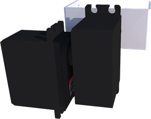
So we just have two servos located at an angle of 90 degrees relative to each other. The first will rotate the second. And the second, in turn, will rotate the stand attached to the labyrinth itself. Below are two pictures illustrating the above.

And to make it even clearer, here's how it looks in action:
To connect the drives I just pulled them tightly with an elastic band. I glued the bottom servo to the old drive mount and secured it to a flat base.
I had to suffer a little with the labyrinth model, but, anyway, the model at the end of the post is quite working, you can print it on your own printer if you wish. I printed it in the size of 9 by 9 cm, because This is the largest size my Makerbot Thing-O-Matic can print.
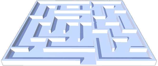
To create the model, I first went to www.mazegenerator.net and created a 9x9 maze there. Then I imported the result into SketchUp, drew the lines and built up the walls. I made the walls so high that the ball did not fall out of the maze, but also did not get stuck.
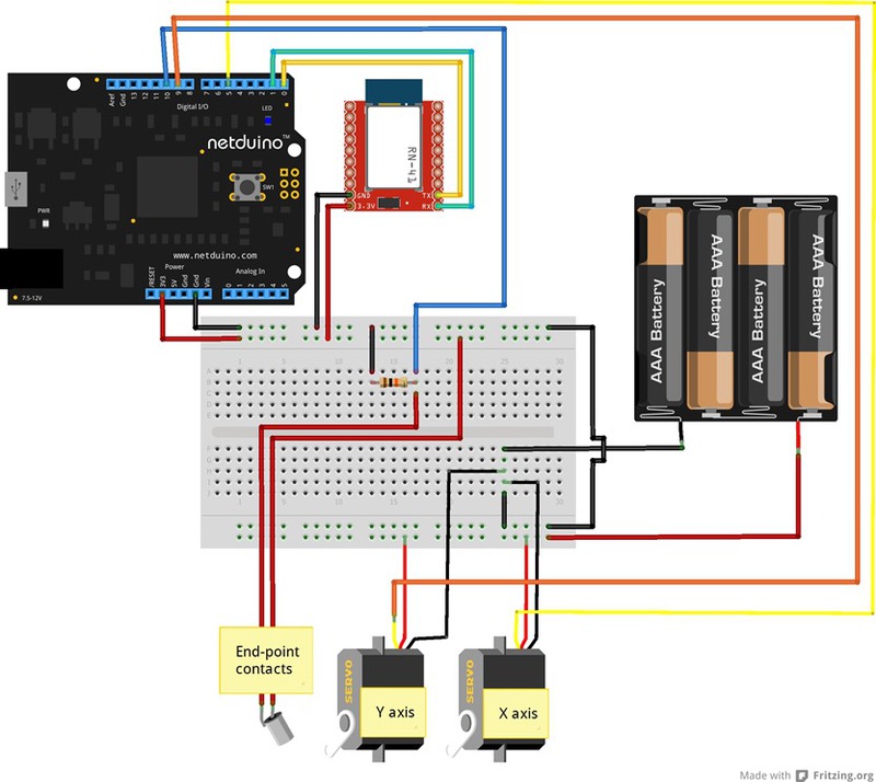
The electronic part is not so complicated.
Note: common wires are positioned to be more visible.
In this case, he joins as well as in my previous projects. The code is exactly the same, so details can be found here:
blog.roguecode.co.za/Post/ControllingaNetduinooverBluetoothwithWP8
blog.roguecode.co.za/Post/MoreNetduino%2bWP8%2bBluetoothfun-3Dreconstruction
blog.roguecode.co.za/Post/ Netduino% 2bSonar% 2bWP8% 2bBluetooth-Controllingsoundwithyourmind
I started this section by directly connecting the servos to the Netduino power connector. I understand that, in general, this is not recommended, as this leads to a large expenditure of energy, but for launching the concept this should be acceptable.
In addition, I had other problems besides power consumption - as soon as the servos started, the Bluetooth module was turned off. This is quite understandable by noise / interference, but I have not come across such a way that it affects any other component so explicitly.
So I connected them to the 4.8V battery pack. It is important to remember that you must connect the battery ground to the Netduino. Signal wires go to the PWM contacts.
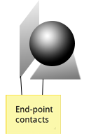
To make the contacts of the end point of the maze, I cut two metal strips and placed one horizontally at the end point, and the second vertically, with a small gap relative to the first. When the ball reaches the end of the maze, it closes the contact between the two pads and activates the switch.
After adding the Bluetooth code (via the links above), the rest becomes quite simple.
To begin with, we install both servos, Bluetooth and a switch on the pad at the end of the maze. To understand how and why switches work on Netduino, follow the link . Then align the servos so that the maze is horizontal.
In an ideal world in which they do not hold on rubber bands, both values will be 90 degrees. The class of drives is taken here .
The code in the event handler will cause the switch to trip when the ball closes the contacts. But, since we do not want this to work over and over again, we will make sure that the current game is running (using the isRunning bool).
In the final part of the code, Netduino processes messages from the phone.
When a player presses the GO button on the phone, the “start” command is sent via Bluetooth. So we set bool to true to show that the game has started.
If the message is not a start message, then we know that these are accelerometer values. As will be understood from the telephone part of the code, we send this data as values along the X and Y axes. The code separates them, then converts them to int values and installs servos. As mentioned earlier, I add a little bias because my drives are not fully calibrated in level.
The phone code is completely simple. Here are the basic functions that it performs:
- Send "start" when the GO button is pressed
- Display a timer
- Send accelerometer values along the X and Y axes
- Display the final game time when receiving "done"
And here is the code for each of them:
Send " start "when the GO button is pressed and display the timer
It should be noted that using DispatcherTimer at such a high frequency is probably not the best idea. And it should not be used except when it is really necessary.
Send accelerometer values along X and Y axes
Those who used MathHelper.Clamp in XNA should learn the functionality. It simply stops the value from exceeding or decreasing beyond the set limit. The code inside Dispatcher takes a few visual steps to show the angle in the UI.
Display the final time after receiving “done”.
That's all, in essence. See source for examples of BT and UI.
The zip file contains the solution for Netduino, the solution for WP8, and the STL model for printing.
Share your projects that used WP8!
When I was a kid, my parents gave me a wooden maze game. I really liked her. I do not think that the labyrinth itself ever worried me, but the tilt mechanism was intriguing and very simple.
Later, I remembered this game and decided to find this game online and my old maze in the pantry.
Now there are a lot of similar games using the phone’s accelerometer, but their graphics are poor. That's why I made a photorealistic version ;-)
The goal was to make a maze that combines old-school and modern versions of the game. So I used the phone to control the tilt of the physical maze via Bluetooth with Netduino. The labyrinth is a simple model printed on a 3D printer and tilted by two servos. The bonus from adding a switch at the end was the feedback from the phone, letting you know about the end of the game.
What we need:
• 2 fairly powerful servos. I used Turnigy TGY-9018MG Metal Gear Servo from HobbyKing
• Bluetooth module
• Netduino
• Small square maze
• 10 kOhm resistor
• Conductive material ball
Mechanism:
Before going into technical details, it is worth understanding the tilting mechanism. The description below may be confusing because it is difficult to explain. So if you feel that you are confused, look at the pictures below, it will become clearer.
Tilt in two directions is implemented by analogy with a wooden game. One servo is attached to the inside of the toy, then a second servo is attached to the outer casing. It is worth noting that in the wooden maze, as many as three boxes are placed one on the other, as can be seen in the first picture of the post. I used the same theory, but simplified it somewhat. The lower part of both axes will not be truly horizontal, which means that the maze will essentially rotate around a conditional inner core.
So we just have two servos located at an angle of 90 degrees relative to each other. The first will rotate the second. And the second, in turn, will rotate the stand attached to the labyrinth itself. Below are two pictures illustrating the above.
And to make it even clearer, here's how it looks in action:
To connect the drives I just pulled them tightly with an elastic band. I glued the bottom servo to the old drive mount and secured it to a flat base.
Labyrinth:
I had to suffer a little with the labyrinth model, but, anyway, the model at the end of the post is quite working, you can print it on your own printer if you wish. I printed it in the size of 9 by 9 cm, because This is the largest size my Makerbot Thing-O-Matic can print.
To create the model, I first went to www.mazegenerator.net and created a 9x9 maze there. Then I imported the result into SketchUp, drew the lines and built up the walls. I made the walls so high that the ball did not fall out of the maze, but also did not get stuck.
Netduino:
The electronic part is not so complicated.
Note: common wires are positioned to be more visible.
Bluetooth module:
In this case, he joins as well as in my previous projects. The code is exactly the same, so details can be found here:
blog.roguecode.co.za/Post/ControllingaNetduinooverBluetoothwithWP8
blog.roguecode.co.za/Post/MoreNetduino%2bWP8%2bBluetoothfun-3Dreconstruction
blog.roguecode.co.za/Post/ Netduino% 2bSonar% 2bWP8% 2bBluetooth-Controllingsoundwithyourmind
Drives
I started this section by directly connecting the servos to the Netduino power connector. I understand that, in general, this is not recommended, as this leads to a large expenditure of energy, but for launching the concept this should be acceptable.
In addition, I had other problems besides power consumption - as soon as the servos started, the Bluetooth module was turned off. This is quite understandable by noise / interference, but I have not come across such a way that it affects any other component so explicitly.
So I connected them to the 4.8V battery pack. It is important to remember that you must connect the battery ground to the Netduino. Signal wires go to the PWM contacts.
End point of the maze:
To make the contacts of the end point of the maze, I cut two metal strips and placed one horizontally at the end point, and the second vertically, with a small gap relative to the first. When the ball reaches the end of the maze, it closes the contact between the two pads and activates the switch.
The code:
After adding the Bluetooth code (via the links above), the rest becomes quite simple.
static SerialPort bt;
      static string buffer = "";
      static Servo servoX;
      static Servo servoY;
      static InterruptPort endStopPort;
      static bool isRunning = false;
      public static void Main()
      {
          servoX = new Servo(Pins.GPIOPIND5);
          servoY = new Servo(Pins.GPIOPIND9);
          bt = new SerialPort(SerialPorts.COM1, 9600, Parity.None, 8, StopBits.One);
          bt.Open();
          endStopPort = new InterruptPort(Pins.GPIOPIND10, false, Port.ResistorMode.Disabled, Port.InterruptMode.InterruptEdgeLevelHigh);
          endStopPort.OnInterrupt += new NativeEventHandler(endStopPortOnInterrupt);
      bt.DataReceived += new SerialDataReceivedEventHandler(btDataReceived);
          servoX.Degree = 90;
          servoY.Degree = 105;
          while (true)
          {
              //do some other stuff here
              Thread.Sleep(1000);
          }
      }
  static void endStopPort_OnInterrupt(uint data1, uint data2, DateTime time)
      {
          if (isRunning)
          {
              isRunning = false;
              byte[] bytes = Encoding.UTF8.GetBytes("done|");
              bt.Write(bytes, 0, bytes.Length);
          }
          Thread.Sleep(1);
          endStopPort.ClearInterrupt();
      }
To begin with, we install both servos, Bluetooth and a switch on the pad at the end of the maze. To understand how and why switches work on Netduino, follow the link . Then align the servos so that the maze is horizontal.
In an ideal world in which they do not hold on rubber bands, both values will be 90 degrees. The class of drives is taken here .
The code in the event handler will cause the switch to trip when the ball closes the contacts. But, since we do not want this to work over and over again, we will make sure that the current game is running (using the isRunning bool).
In the final part of the code, Netduino processes messages from the phone.
private static void DoSomething(string buffer)
        {
            if (buffer == "start")
            {
                isRunning = true;
            }
            else
            {
                string[] split = buffer.Split(new char[] { ',' });
                if (split.Length == 2)
                {
                    int x = int.Parse(split[0]);
                    int y = int.Parse(split[1]);
                    servoX.Degree = x + 3;
                    servoY.Degree = y + 12;
                    Debug.Print(x + " " + y);
                }
            }
        }
When a player presses the GO button on the phone, the “start” command is sent via Bluetooth. So we set bool to true to show that the game has started.
If the message is not a start message, then we know that these are accelerometer values. As will be understood from the telephone part of the code, we send this data as values along the X and Y axes. The code separates them, then converts them to int values and installs servos. As mentioned earlier, I add a little bias because my drives are not fully calibrated in level.
WP8:
The phone code is completely simple. Here are the basic functions that it performs:
- Send "start" when the GO button is pressed
- Display a timer
- Send accelerometer values along the X and Y axes
- Display the final game time when receiving "done"
And here is the code for each of them:
Send " start "when the GO button is pressed and display the timer
private void goBtnClick1(object sender, RoutedEventArgs e)
{
    Write("start");
    secTxt.Text = "";
    msText.Text = "";
    startedDT = DateTime.Now;
    TimeSpan timeTaken;
    _timer = new DispatcherTimer { Interval = new TimeSpan(0, 0, 0, 0, 51) };
    _timer.Tick += (s, ev) =>
        {
            timeTaken = DateTime.Now.Subtract(startedDT);
            secTxt.Text = timeTaken.Seconds.ToString();
            msText.Text = timeTaken.Milliseconds.ToString();
        };
    _timer.Start();
    goBtn.Visibility = System.Windows.Visibility.Collapsed;
    stopBtn.Visibility = System.Windows.Visibility.Visible;
    timerDisplayContainer.Visibility = System.Windows.Visibility.Visible;
}
It should be noted that using DispatcherTimer at such a high frequency is probably not the best idea. And it should not be used except when it is really necessary.
Send accelerometer values along X and Y axes
 void accReadingChanged(Accelerometer sender, AccelerometerReadingChangedEventArgs args)
        {
            Write(Convert(args.Reading.AccelerationX) + "," + Convert(-args.Reading.AccelerationY) + "|");
            Dispatcher.BeginInvoke(() =>
                {
                    xRight.Opacity = args.Reading.AccelerationX * 2;
                    xLeft.Opacity = -args.Reading.AccelerationX * 2;
                    yTop.Opacity = args.Reading.AccelerationY * 2;
                    yBottom.Opacity = -args.Reading.AccelerationY * 2;
                });
        }
private string Convert(double val)
        {
            return ((int)((Clamp((val * 2d), -1, 1) * 10) + 90)).ToString();
            //first double it so full range is -45deg to 45deg
        //clamp the above value to the max of -1 and 1
            //then multiple by the max angle we want the servos to goto
            //then add 90 because servos go from 0 to 180, not -90 to 90
        }
private double Clamp(double value, double min, double max)
        {
            return value < min ? min : value > max ? max : value;
        }
Those who used MathHelper.Clamp in XNA should learn the functionality. It simply stops the value from exceeding or decreasing beyond the set limit. The code inside Dispatcher takes a few visual steps to show the angle in the UI.
Display the final time after receiving “done”.
private void DoSomethingWithReceivedString(string receivedBuffer)
{
    if (receivedBuffer == "done")
    {
        timer.Stop();
        stopBtn.Visibility = System.Windows.Visibility.Collapsed;
        goBtn.Visibility = System.Windows.Visibility.Visible;
        TimeSpan timeTaken = DateTime.Now.Subtract(startedDT);
        MessageBox.Show(string.Format("You took {0}:{1}", timeTaken.Seconds, timeTaken.Milliseconds), "Done!", MessageBoxButton.OK);
    }
}
That's all, in essence. See source for examples of BT and UI.
Downloads:
The zip file contains the solution for Netduino, the solution for WP8, and the STL model for printing.
Share your projects that used WP8!