Signed Distance Field Basics in 2D
- Transfer
Although meshes are the simplest and most versatile way to render, there are other options for representing shapes in 2d and 3d. One commonly used method is signed distance fields (SDF). Signed distance fields provide less costly ray tracing, allow different shapes to flow smoothly into each other and save on low-resolution textures for high-quality images.
We will start by generating the sign of the distance fields using functions in two dimensions, but later we will continue to generate them in 3D. I will use the coordinates of the world space so that we have as little as possible the dependence on scaling and UV-coordinates, so if you do not understand how it works, then study this tutorial on a flat overlaywhich explains what happens.
We will temporarily throw away the properties from the base flat overlay shader, because for now we’ll take care of the technical basis. Then we write the position of the vertex in the world directly to the fragment structure, and we will not first convert it to UV. At the last stage of preparation, we will write a new function that calculates the scene and returns the distance to the nearest surface. Then we call the functions and use the result as a color.
I will write all the functions for the signed distance fields in a separate file so that we can use them repeatedly. To do this, I will create a new file. We will add no evil to it, then we set it and complete the conditional include protection, checking first whether the preprocessor variable is set. If it is not defined yet, then we define it and complete the conditional if construct after the functions that we want to include. The advantage of this is that if we add the file twice (for example, if we add two different files, each of which has the functions we need, and they both add the same file), then this will break the shader. If you are sure that this will never happen, then you can not perform this check.
If the include file is located in the same folder as the main shader, we can simply include it using the pragma construct.
So we will see only a black surface on the rendered surface, ready to display the distance with a sign on it.
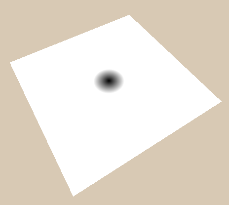
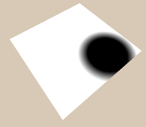
The simplest function of the signed distance field is the circle function. The function will receive only the position of the sample and the radius of the circle. We start by getting the length of the sample position vector. So we get a point at position (0, 0), which is similar to a circle with a radius of 0.
Then you can call the circle function in the scene function and return the distance it returns.
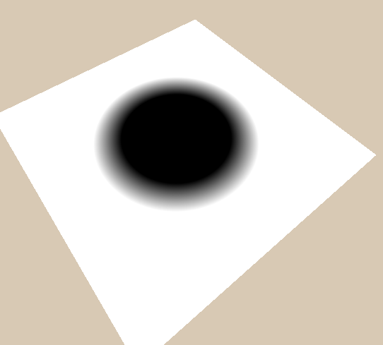
Then we add the radius to the calculations. An important aspect of the signed distance functions is that when we are inside the object, we get a negative distance to the surface (this is what the word signed means in the expression signed distance field). To increase the circle to a radius, we simply subtract the radius from the length. Thus the surface, which is everywhere where the function returns 0, moves outward. That which is in two units of the distance from the surface for a circle with a size of 0, is only one unit from a circle with a radius of 1, and one unit inside the circle (the value is -1) for a circle with a radius of 3;
Now the only thing we cannot do is move the circle from the center. To fix this, you can add a new argument to the circle function to calculate the distance between the sample position and the center of the circle, and subtract the radius from this value to define a circle. Or, you can redefine the origin by moving the space of the sample point, and then get a circle in that space. The second option looks much more complicated, but since moving objects is an operation that we want to use for all figures, it is much more universal, and therefore I will explain it.
"Transformation of the space of a point" - sounds much worse than it actually is. This means that we pass the point to the function, and the function changes it so that we can still use it in the future. In the case of a transfer, we simply subtract the offset from the point. The position is subtracted when we want to move the shapes in the positive direction, because the shapes that we render in space move in the opposite direction to moving the space.
For example, if we want to draw a sphere in a position
Another simple shape is a rectangle. To begin with, we consider the components separately. First we get the distance from the center, taking the absolute value. Then, similarly to a circle, we subtract half the size (which essentially resembles the radius of a rectangle). To just show how the results will look, we will return only one component for now.
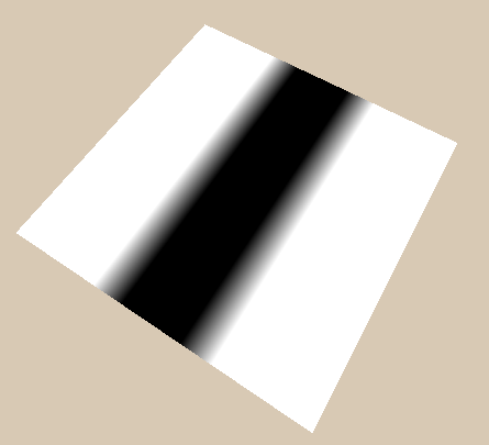
Now we can get a cheap version of the rectangle by simply returning the largest component 2. This works in many cases, but not correctly, because it does not display the correct distance around the corners.
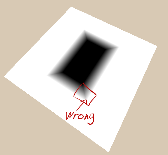
The correct values for the rectangle outside the figure can be obtained by first taking the maximum between the distances to the edges and 0, and then taking its length.
If we do not limit the distance from below to 0, then we simply calculate the distance to the corners (where edgeDistances are equal
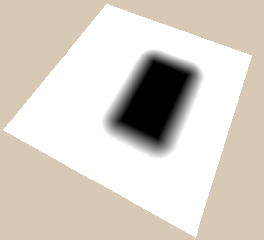
To correct the distance 0 for the entire inner part, you need to generate the internal distance, simply using the cheap rectangle formula (taking the maximum value from the x and y component), and then guaranteeing that it will never exceed 0, taking the minimum value from it to 0. Then we add the external distance, which is never lower than 0, and the internal distance, which never exceeds 0, and we obtain the finished distance function.
Since we previously recorded the transfer function in a universal form, now we can also use it to move its center to any place.
Rotating shapes is similar to moving. Before calculating the distance to the figure, we rotate the coordinates in the opposite direction. To simplify understanding of rotations as much as possible, we multiply the rotation by 2 * pi to get the angle in radians. Thus, we pass a rotation to the function, where 0.25 is a quarter of a turn, 0.5 is a half of a turn, and 1 is a full turn (you can perform conversions differently if it seems more natural to you). We also invert the rotation, because we need to rotate the position in the opposite direction from the rotation of the figure for the same reason as when moving.
To calculate the rotated coordinates, we first calculate the sine and cosine based on the angle. Hlsl has a sincos function that calculates both of these values faster than when calculated separately.
When constructing a new vector for component x, we take the original component x multiplied by cosine and the component y multiplied by sine. This can be easily remembered if you remember that the cosine of 0 is 1, and when rotated by 0, we want the component x of the new vector to be exactly the same as before (that is, multiply by 1). Component y, which previously pointed upward, made no contribution to component x, rotates to the right, and its values start at 0, at first becoming larger, that is, its motion is completely described by a sine.
For the component y of the new vector, we multiply the cosine by the component y of the old vector and subtract the sine multiplied by the old component x. To understand why we subtract, rather than add the sine multiplied by the component x, it is best to imagine how the vector changes
Now that we have written the rotation method, we can use it in combination with the transfer to move and rotate the figure.
In this case, we first rotate the object around the center of the whole scene, so that the rotation also affects the transfer. To rotate a figure relative to its own center, you first need to move it, and then rotate it. Due to this changed order by the time of rotation, the center of the figure will become the center of the coordinate system.
Scaling works similarly to other ways to transform shapes. We divide the coordinates by scale, rendering the figure in space with a reduced scale, and in the base coordinate system they become larger.
Although this performs the scaling correctly, the distance also scales. The main advantage of the signed distance field is that we always know the distance to the nearest surface, but zooming out completely destroys this property. This can be easily fixed by multiplying the distance field obtained from the distance function with a sign (in our case
Signed distance fields can be used for a variety of things, such as creating shadows, rendering 3D scenes, physics, and rendering text. But we don’t want to go deep into complexity yet, therefore I will explain only two techniques of their visualization. The first is a clear form with antialiasing, the second is the rendering of lines depending on the distance.
This method is similar to the one that is often used when rendering text, it creates a clear form. If we want to generate a distance field not from a function, but to read it from a texture, this allows us to use textures with a much lower resolution than usual and get good results. TextMesh Pro uses this technique to render text.
To apply this technique, we take advantage of the fact that the data in the distance fields is signed, and we know the cut-off point. We start by calculating how far the distance field changes to the next pixel. This should be the same value as the length of the coordinate change, but it is easier and more reliable to calculate the distance with a sign.
Having received the distance change, we can do a smoothstepfrom half the change in distance to minus / plus half the change in distance. This will perform a simple clipping around about 0, but with smoothing. Then you can use this smoothed value for any binary value we need. In this example, I will change the shader to a transparency shader and use it for the alpha channel. I do a smoothstep from a positive to a negative value because we want the negative value of the distance field to be visible. If you don’t quite understand how transparency rendering works here, then I recommend reading my transparency rendering tutorial .

Another common technique for visualizing distance fields is to display distances as lines. In our implementation, I will add a few thick lines and a few thin lines between them. I will also paint the inside and outside of the figure in different colors so that you can see where the object is.
We will start by displaying the difference between the inside and outside of the figure. Colors can be customized in the material, so we will add new properties, as well as shader variables for the internal and external colors of the figure.
Then in the fragment shader we check where the pixel is located, which we render by comparing the distance with the sign with 0 using the function
To render lines, we first need to specify how often we will render lines, and how thick they will be, setting the properties and corresponding shader variables.
Then, to render the lines, we will start by calculating the change in distance so that we can use it later for smoothing. We also already divided it by 2, because later we add half of it and subtract half of it to cover the change distance of 1 pixel.
Then we take the distance and transform it so that it has the same behavior at repeating points. To do this, we first divide it by the distance between the lines, while we will not get full numbers at each first step, but full numbers only on the basis of the distance we set.
Then we add 0.5 to the number, take the fractional part and subtract 0.5 again. The fractional part and the subtraction are needed here so that the line passes through zero in the repeating pattern. We add 0.5 to obtain the fractional part in order to neutralize further subtraction of 0.5 - the offset will lead to the fact that the values at which the graph is 0 are at 0, 1, 2, etc., and not at 0.5, 1.5, etc.
The last steps to convert the value - we take the absolute value and again multiply it by the distance between the lines. The absolute value makes the areas before and after the points of the line remain the same, which makes it easier to create clipping for the lines. The last operation, in which we again multiply the value by the distance between the lines, is needed to neutralize the division at the beginning of the equation, thanks to it, the change in the value is again the same as at the beginning, and the previously calculated change in the distance is still correct.

Now that we have calculated the distance to the lines based on the distance to the figure, we can draw the lines. We do a smoothstep from linethickness minus half the change in distance to linethickness plus half the change in distance and use the line distance just calculated as a value for comparison. After calculating this value, we multiply it by color to create black lines (you can also lerp to a different color if you need multi-colored lines).
We implement thin lines between thick ones in the same way - we add a property that determines how many thin lines should be between thick ones, and then we do what we did with thick ones, but because of the distance between thin lines we divide the distance between thick ones by the number of thin lines between them. We will also make the number of thin lines
I hope I managed to explain the basics of the distance fields with a sign, and you are already waiting for a few new tutorials in which I will talk about other ways to use them.
We will start by generating the sign of the distance fields using functions in two dimensions, but later we will continue to generate them in 3D. I will use the coordinates of the world space so that we have as little as possible the dependence on scaling and UV-coordinates, so if you do not understand how it works, then study this tutorial on a flat overlaywhich explains what happens.
Foundation preparation
We will temporarily throw away the properties from the base flat overlay shader, because for now we’ll take care of the technical basis. Then we write the position of the vertex in the world directly to the fragment structure, and we will not first convert it to UV. At the last stage of preparation, we will write a new function that calculates the scene and returns the distance to the nearest surface. Then we call the functions and use the result as a color.
Shader "Tutorial/034_2D_SDF_Basics"{
    SubShader{
        //материал полностью непрозрачен и рендерится одновременно со всей другой непрозрачной геометрией
        Tags{ "RenderType"="Opaque" "Queue"="Geometry"}
        Pass{
            CGPROGRAM
            #include "UnityCG.cginc"
            #pragma vertex vert
            #pragma fragment frag
            struct appdata{
                float4 vertex : POSITION;
            };
            struct v2f{
                float4 position : SV_POSITION;
                float4 worldPos : TEXCOORD0;
            };
            v2f vert(appdata v){
                v2f o;
                //вычисляем позицию в пространстве усечённых координат для рендеринга объекта
                o.position = UnityObjectToClipPos(v.vertex);
                //вычисляем позицию вершины в мире
                o.worldPos = mul(unity_ObjectToWorld, v.vertex);
                return o;
            }
            float scene(float2 position) {
                // вычисляем расстояние до ближайшей поверхности
                return 0;
            }
            fixed4 frag(v2f i) : SV_TARGET{
                float dist = scene(i.worldPos.xz);
                fixed4 col = fixed4(dist, dist, dist, 1);
                return col;
            }
            ENDCG
        }
    }
    FallBack "Standard" //fallback добавляет проход тени, чтобы создавать тени на других объектах
}
I will write all the functions for the signed distance fields in a separate file so that we can use them repeatedly. To do this, I will create a new file. We will add no evil to it, then we set it and complete the conditional include protection, checking first whether the preprocessor variable is set. If it is not defined yet, then we define it and complete the conditional if construct after the functions that we want to include. The advantage of this is that if we add the file twice (for example, if we add two different files, each of which has the functions we need, and they both add the same file), then this will break the shader. If you are sure that this will never happen, then you can not perform this check.
// in include file
// include guards that keep the functions from being included more than once
#ifndef SDF_2D
#define SDF_2D
// functions
#endif
If the include file is located in the same folder as the main shader, we can simply include it using the pragma construct.
// in main shader
#include "2D_SDF.cginc"
So we will see only a black surface on the rendered surface, ready to display the distance with a sign on it.
A circle
The simplest function of the signed distance field is the circle function. The function will receive only the position of the sample and the radius of the circle. We start by getting the length of the sample position vector. So we get a point at position (0, 0), which is similar to a circle with a radius of 0.
float circle(float2 samplePosition, float radius){
    return length(samplePosition);
}
Then you can call the circle function in the scene function and return the distance it returns.
float scene(float2 position) {
    float sceneDistance = circle(position, 2);
    return sceneDistance;
}
Then we add the radius to the calculations. An important aspect of the signed distance functions is that when we are inside the object, we get a negative distance to the surface (this is what the word signed means in the expression signed distance field). To increase the circle to a radius, we simply subtract the radius from the length. Thus the surface, which is everywhere where the function returns 0, moves outward. That which is in two units of the distance from the surface for a circle with a size of 0, is only one unit from a circle with a radius of 1, and one unit inside the circle (the value is -1) for a circle with a radius of 3;
float circle(float2 samplePosition, float radius){
    return length(samplePosition) - radius;
}
Now the only thing we cannot do is move the circle from the center. To fix this, you can add a new argument to the circle function to calculate the distance between the sample position and the center of the circle, and subtract the radius from this value to define a circle. Or, you can redefine the origin by moving the space of the sample point, and then get a circle in that space. The second option looks much more complicated, but since moving objects is an operation that we want to use for all figures, it is much more universal, and therefore I will explain it.
Moving
"Transformation of the space of a point" - sounds much worse than it actually is. This means that we pass the point to the function, and the function changes it so that we can still use it in the future. In the case of a transfer, we simply subtract the offset from the point. The position is subtracted when we want to move the shapes in the positive direction, because the shapes that we render in space move in the opposite direction to moving the space.
For example, if we want to draw a sphere in a position
(3, 4), then we need to change the space so that we (3, 4)turn into (0, 0), and for this we need to subtract (3, 4). Now if we draw a sphere around a new origin, then it will be an old point(3, 4).// in sdf functions include file
float2 translate(float2 samplePosition, float2 offset){
return samplePosition - offset;
}float scene(float2 position) {
float2 circlePosition = translate(position, float2(3, 2));
float sceneDistance = circle(circlePosition, 2);
return sceneDistance;
}Rectangle
Another simple shape is a rectangle. To begin with, we consider the components separately. First we get the distance from the center, taking the absolute value. Then, similarly to a circle, we subtract half the size (which essentially resembles the radius of a rectangle). To just show how the results will look, we will return only one component for now.
float rectangle(float2 samplePosition, float2 halfSize){
    float2 componentWiseEdgeDistance = abs(samplePosition) - halfSize;
    return componentWiseEdgeDistance.x;
}
Now we can get a cheap version of the rectangle by simply returning the largest component 2. This works in many cases, but not correctly, because it does not display the correct distance around the corners.
The correct values for the rectangle outside the figure can be obtained by first taking the maximum between the distances to the edges and 0, and then taking its length.
If we do not limit the distance from below to 0, then we simply calculate the distance to the corners (where edgeDistances are equal
(0, 0)), but the coordinates between the corners will not fall below 0, so the whole edge will be used. The disadvantage of this is that 0 is used as the distance from the edge for the entire inside of the figure.To correct the distance 0 for the entire inner part, you need to generate the internal distance, simply using the cheap rectangle formula (taking the maximum value from the x and y component), and then guaranteeing that it will never exceed 0, taking the minimum value from it to 0. Then we add the external distance, which is never lower than 0, and the internal distance, which never exceeds 0, and we obtain the finished distance function.
float rectangle(float2 samplePosition, float2 halfSize){
    float2 componentWiseEdgeDistance = abs(samplePosition) - halfSize;
    float outsideDistance = length(max(componentWiseEdgeDistance, 0));
    float insideDistance = min(max(componentWiseEdgeDistance.x, componentWiseEdgeDistance.y), 0);
    return outsideDistance + insideDistance;
}
Since we previously recorded the transfer function in a universal form, now we can also use it to move its center to any place.
float scene(float2 position) {
    float2 circlePosition = translate(position, float2(1, 0));
    float sceneDistance = rectangle(circlePosition, float2(1, 2));
    return sceneDistance;
}
Turn
Rotating shapes is similar to moving. Before calculating the distance to the figure, we rotate the coordinates in the opposite direction. To simplify understanding of rotations as much as possible, we multiply the rotation by 2 * pi to get the angle in radians. Thus, we pass a rotation to the function, where 0.25 is a quarter of a turn, 0.5 is a half of a turn, and 1 is a full turn (you can perform conversions differently if it seems more natural to you). We also invert the rotation, because we need to rotate the position in the opposite direction from the rotation of the figure for the same reason as when moving.
To calculate the rotated coordinates, we first calculate the sine and cosine based on the angle. Hlsl has a sincos function that calculates both of these values faster than when calculated separately.
When constructing a new vector for component x, we take the original component x multiplied by cosine and the component y multiplied by sine. This can be easily remembered if you remember that the cosine of 0 is 1, and when rotated by 0, we want the component x of the new vector to be exactly the same as before (that is, multiply by 1). Component y, which previously pointed upward, made no contribution to component x, rotates to the right, and its values start at 0, at first becoming larger, that is, its motion is completely described by a sine.
For the component y of the new vector, we multiply the cosine by the component y of the old vector and subtract the sine multiplied by the old component x. To understand why we subtract, rather than add the sine multiplied by the component x, it is best to imagine how the vector changes
(1, 0)when turning clockwise. The y component of the result starts at 0 and then becomes less than 0. This is the opposite of how the sine behaves, so we change sign.float2 rotate(float2 samplePosition, float rotation){
const float PI = 3.14159;
float angle = rotation * PI * 2 * -1;
float sine, cosine;
sincos(angle, sine, cosine);
return float2(cosine * samplePosition.x + sine * samplePosition.y, cosine * samplePosition.y - sine * samplePosition.x);
}Now that we have written the rotation method, we can use it in combination with the transfer to move and rotate the figure.
float scene(float2 position) {
float2 circlePosition = position;
circlePosition = rotate(circlePosition, _Time.y);
circlePosition = translate(circlePosition, float2(2, 0));
float sceneDistance = rectangle(circlePosition, float2(1, 2));
return sceneDistance;
}In this case, we first rotate the object around the center of the whole scene, so that the rotation also affects the transfer. To rotate a figure relative to its own center, you first need to move it, and then rotate it. Due to this changed order by the time of rotation, the center of the figure will become the center of the coordinate system.
float scene(float2 position) {
float2 circlePosition = position;
circlePosition = translate(circlePosition, float2(2, 0));
circlePosition = rotate(circlePosition, _Time.y);
float sceneDistance = rectangle(circlePosition, float2(1, 2));
return sceneDistance;
}Scaling
Scaling works similarly to other ways to transform shapes. We divide the coordinates by scale, rendering the figure in space with a reduced scale, and in the base coordinate system they become larger.
float2 scale(float2 samplePosition, float scale){
return samplePosition / scale;
}float scene(float2 position) {
float2 circlePosition = position;
circlePosition = translate(circlePosition, float2(0, 0));
circlePosition = rotate(circlePosition, .125);
float pulseScale = 1 + 0.5*sin(_Time.y * 3.14);
circlePosition = scale(circlePosition, pulseScale);
float sceneDistance = rectangle(circlePosition, float2(1, 2));
return sceneDistance;
}Although this performs the scaling correctly, the distance also scales. The main advantage of the signed distance field is that we always know the distance to the nearest surface, but zooming out completely destroys this property. This can be easily fixed by multiplying the distance field obtained from the distance function with a sign (in our case
rectangle) by the scale. For the same reason, we cannot easily scale unevenly (with different scales for the x and y axes).float scene(float2 position) {
float2 circlePosition = position;
circlePosition = translate(circlePosition, float2(0, 0));
circlePosition = rotate(circlePosition, .125);
float pulseScale = 1 + 0.5*sin(_Time.y * 3.14);
circlePosition = scale(circlePosition, pulseScale);
float sceneDistance = rectangle(circlePosition, float2(1, 2)) * pulseScale;
return sceneDistance;
}Visualization
Signed distance fields can be used for a variety of things, such as creating shadows, rendering 3D scenes, physics, and rendering text. But we don’t want to go deep into complexity yet, therefore I will explain only two techniques of their visualization. The first is a clear form with antialiasing, the second is the rendering of lines depending on the distance.
Clear form
This method is similar to the one that is often used when rendering text, it creates a clear form. If we want to generate a distance field not from a function, but to read it from a texture, this allows us to use textures with a much lower resolution than usual and get good results. TextMesh Pro uses this technique to render text.
To apply this technique, we take advantage of the fact that the data in the distance fields is signed, and we know the cut-off point. We start by calculating how far the distance field changes to the next pixel. This should be the same value as the length of the coordinate change, but it is easier and more reliable to calculate the distance with a sign.
Having received the distance change, we can do a smoothstepfrom half the change in distance to minus / plus half the change in distance. This will perform a simple clipping around about 0, but with smoothing. Then you can use this smoothed value for any binary value we need. In this example, I will change the shader to a transparency shader and use it for the alpha channel. I do a smoothstep from a positive to a negative value because we want the negative value of the distance field to be visible. If you don’t quite understand how transparency rendering works here, then I recommend reading my transparency rendering tutorial .
//properties
Properties{
_Color("Color", Color) = (1,1,1,1)
}//in subshader outside of pass
Tags{ "RenderType"="Transparent" "Queue"="Transparent"}
Blend SrcAlpha OneMinusSrcAlpha
ZWrite Offfixed4 frag(v2f i) : SV_TARGET{
float dist = scene(i.worldPos.xz);
float distanceChange = fwidth(dist) * 0.5;
float antialiasedCutoff = smoothstep(distanceChange, -distanceChange, dist);
fixed4 col = fixed4(_Color, antialiasedCutoff);
return col;
}Elevation lines
Another common technique for visualizing distance fields is to display distances as lines. In our implementation, I will add a few thick lines and a few thin lines between them. I will also paint the inside and outside of the figure in different colors so that you can see where the object is.
We will start by displaying the difference between the inside and outside of the figure. Colors can be customized in the material, so we will add new properties, as well as shader variables for the internal and external colors of the figure.
Properties{
_InsideColor("Inside Color", Color) = (.5, 0, 0, 1)
_OutsideColor("Outside Color", Color) = (0, .5, 0, 1)
}//global shader variables
float4 _InsideColor;
float4 _OutsideColor;Then in the fragment shader we check where the pixel is located, which we render by comparing the distance with the sign with 0 using the function
step. We use this variable to interpolate from inner to outer color and render it on the screen.fixed4 frag(v2f i) : SV_TARGET{
float dist = scene(i.worldPos.xz);
fixed4 col = lerp(_InsideColor, _OutsideColor, step(0, dist));
return col;
}To render lines, we first need to specify how often we will render lines, and how thick they will be, setting the properties and corresponding shader variables.
//Properties
_LineDistance("Mayor Line Distance", Range(0, 2)) = 1
_LineThickness("Mayor Line Thickness", Range(0, 0.1)) = 0.05//shader variables
float _LineDistance;
float _LineThickness;Then, to render the lines, we will start by calculating the change in distance so that we can use it later for smoothing. We also already divided it by 2, because later we add half of it and subtract half of it to cover the change distance of 1 pixel.
float distanceChange = fwidth(dist) * 0.5;Then we take the distance and transform it so that it has the same behavior at repeating points. To do this, we first divide it by the distance between the lines, while we will not get full numbers at each first step, but full numbers only on the basis of the distance we set.
Then we add 0.5 to the number, take the fractional part and subtract 0.5 again. The fractional part and the subtraction are needed here so that the line passes through zero in the repeating pattern. We add 0.5 to obtain the fractional part in order to neutralize further subtraction of 0.5 - the offset will lead to the fact that the values at which the graph is 0 are at 0, 1, 2, etc., and not at 0.5, 1.5, etc.
The last steps to convert the value - we take the absolute value and again multiply it by the distance between the lines. The absolute value makes the areas before and after the points of the line remain the same, which makes it easier to create clipping for the lines. The last operation, in which we again multiply the value by the distance between the lines, is needed to neutralize the division at the beginning of the equation, thanks to it, the change in the value is again the same as at the beginning, and the previously calculated change in the distance is still correct.
float majorLineDistance = abs(frac(dist / _LineDistance + 0.5) - 0.5) * _LineDistance;Now that we have calculated the distance to the lines based on the distance to the figure, we can draw the lines. We do a smoothstep from linethickness minus half the change in distance to linethickness plus half the change in distance and use the line distance just calculated as a value for comparison. After calculating this value, we multiply it by color to create black lines (you can also lerp to a different color if you need multi-colored lines).
fixed4 frag(v2f i) : SV_TARGET{
float dist = scene(i.worldPos.xz);
fixed4 col = lerp(_InsideColor, _OutsideColor, step(0, dist));
float distanceChange = fwidth(dist) * 0.5;
float majorLineDistance = abs(frac(dist / _LineDistance + 0.5) - 0.5) * _LineDistance;
float majorLines = smoothstep(_LineThickness - distanceChange, _LineThickness + distanceChange, majorLineDistance);
return col * majorLines;
}We implement thin lines between thick ones in the same way - we add a property that determines how many thin lines should be between thick ones, and then we do what we did with thick ones, but because of the distance between thin lines we divide the distance between thick ones by the number of thin lines between them. We will also make the number of thin lines
IntRange, thanks to this we can assign only integer values and do not get thin lines that do not correspond to thick ones. After calculating thin lines, we multiply them by color in the same way as thick ones.//properties
[IntRange]_SubLines("Lines between major lines", Range(1, 10)) = 4
_SubLineThickness("Thickness of inbetween lines", Range(0, 0.05)) = 0.01//shader variables
float _SubLines;
float _SubLineThickness;fixed4 frag(v2f i) : SV_TARGET{
float dist = scene(i.worldPos.xz);
fixed4 col = lerp(_InsideColor, _OutsideColor, step(0, dist));
float distanceChange = fwidth(dist) * 0.5;
float majorLineDistance = abs(frac(dist / _LineDistance + 0.5) - 0.5) * _LineDistance;
float majorLines = smoothstep(_LineThickness - distanceChange, _LineThickness + distanceChange, majorLineDistance);
float distanceBetweenSubLines = _LineDistance / _SubLines;
float subLineDistance = abs(frac(dist / distanceBetweenSubLines + 0.5) - 0.5) * distanceBetweenSubLines;
float subLines = smoothstep(_SubLineThickness - distanceChange, _SubLineThickness + distanceChange, subLineDistance);
return col * majorLines * subLines;
}Source
2D SDF Features
#ifndef SDF_2D
#define SDF_2D
float2 rotate(float2 samplePosition, float rotation){
    const float PI = 3.14159;
    float angle = rotation * PI * 2 * -1;
    float sine, cosine;
    sincos(angle, sine, cosine);
    return float2(cosine * samplePosition.x + sine * samplePosition.y, cosine * samplePosition.y - sine * samplePosition.x);
}
float2 translate(float2 samplePosition, float2 offset){
//move samplepoint in the opposite direction that we want to move shapes in
return samplePosition - offset;
}
float2 scale(float2 samplePosition, float scale){
    return samplePosition / scale;
}
float circle(float2 samplePosition, float radius){
//get distance from center and grow it according to radius
return length(samplePosition) - radius;
}
float rectangle(float2 samplePosition, float2 halfSize){
float2 componentWiseEdgeDistance = abs(samplePosition) - halfSize;
float outsideDistance = length(max(componentWiseEdgeDistance, 0));
float insideDistance = min(max(componentWiseEdgeDistance.x, componentWiseEdgeDistance.y), 0);
return outsideDistance + insideDistance;
}
#endifCircle example
Shader "Tutorial/034_2D_SDF_Basics/Rectangle"{
SubShader{
//the material is completely non-transparent and is rendered at the same time as the other opaque geometry
Tags{ "RenderType"="Opaque" "Queue"="Geometry"}
Pass{
CGPROGRAM
#include "UnityCG.cginc"
#include "2D_SDF.cginc"
#pragma vertex vert
#pragma fragment frag
struct appdata{
float4 vertex : POSITION;
};
struct v2f{
float4 position : SV_POSITION;
float4 worldPos : TEXCOORD0;
};
v2f vert(appdata v){
v2f o;
//calculate the position in clip space to render the object
o.position = UnityObjectToClipPos(v.vertex);
//calculate world position of vertex
o.worldPos = mul(unity_ObjectToWorld, v.vertex);
return o;
}
float scene(float2 position) {
float2 circlePosition = position;
circlePosition = rotate(circlePosition, _Time.y * 0.5);
circlePosition = translate(circlePosition, float2(2, 0));
float sceneDistance = rectangle(circlePosition, float2(1, 2));
return sceneDistance;
}
fixed4 frag(v2f i) : SV_TARGET{
float dist = scene(i.worldPos.xz);
fixed4 col = fixed4(dist, dist, dist, 1);
return col;
}
ENDCG
}
}
FallBack "Standard" //fallback adds a shadow pass so we get shadows on other objects
}Rectangle example
Shader "Tutorial/034_2D_SDF_Basics/Rectangle"{
SubShader{
//the material is completely non-transparent and is rendered at the same time as the other opaque geometry
Tags{ "RenderType"="Opaque" "Queue"="Geometry"}
Pass{
CGPROGRAM
#include "UnityCG.cginc"
#include "2D_SDF.cginc"
#pragma vertex vert
#pragma fragment frag
struct appdata{
float4 vertex : POSITION;
};
struct v2f{
float4 position : SV_POSITION;
float4 worldPos : TEXCOORD0;
};
v2f vert(appdata v){
v2f o;
//calculate the position in clip space to render the object
o.position = UnityObjectToClipPos(v.vertex);
//calculate world position of vertex
o.worldPos = mul(unity_ObjectToWorld, v.vertex);
return o;
}
float scene(float2 position) {
float2 circlePosition = position;
circlePosition = rotate(circlePosition, _Time.y * 0.5);
circlePosition = translate(circlePosition, float2(2, 0));
float sceneDistance = rectangle(circlePosition, float2(1, 2));
return sceneDistance;
}
fixed4 frag(v2f i) : SV_TARGET{
float dist = scene(i.worldPos.xz);
fixed4 col = fixed4(dist, dist, dist, 1);
return col;
}
ENDCG
}
}
FallBack "Standard" //fallback adds a shadow pass so we get shadows on other objects
}Cutoff
Shader "Tutorial/034_2D_SDF_Basics/Cutoff"{
Properties{
_Color("Color", Color) = (1,1,1,1)
}
SubShader{
Tags{ "RenderType"="Transparent" "Queue"="Transparent"}
Blend SrcAlpha OneMinusSrcAlpha
ZWrite Off
Pass{
CGPROGRAM
#include "UnityCG.cginc"
#include "2D_SDF.cginc"
#pragma vertex vert
#pragma fragment frag
struct appdata{
float4 vertex : POSITION;
};
struct v2f{
float4 position : SV_POSITION;
float4 worldPos : TEXCOORD0;
};
fixed3 _Color;
v2f vert(appdata v){
v2f o;
//calculate the position in clip space to render the object
o.position = UnityObjectToClipPos(v.vertex);
//calculate world position of vertex
o.worldPos = mul(unity_ObjectToWorld, v.vertex);
return o;
}
float scene(float2 position) {
float2 circlePosition = position;
circlePosition = rotate(circlePosition, _Time.y * 0.5);
circlePosition = translate(circlePosition, float2(2, 0));
float sceneDistance = rectangle(circlePosition, float2(1, 2));
return sceneDistance;
}
fixed4 frag(v2f i) : SV_TARGET{
    float dist = scene(i.worldPos.xz);
    float distanceChange = fwidth(dist) * 0.5;
    float antialiasedCutoff = smoothstep(distanceChange, -distanceChange, dist);
    fixed4 col = fixed4(_Color, antialiasedCutoff);
    return col;
}
ENDCG
}
}
FallBack "Standard" //fallback adds a shadow pass so we get shadows on other objects
}Distance lines
Shader "Tutorial/034_2D_SDF_Basics/DistanceLines"{
Properties{
_InsideColor("Inside Color", Color) = (.5, 0, 0, 1)
_OutsideColor("Outside Color", Color) = (0, .5, 0, 1)
_LineDistance("Mayor Line Distance", Range(0, 2)) = 1
_LineThickness("Mayor Line Thickness", Range(0, 0.1)) = 0.05
[IntRange]_SubLines("Lines between major lines", Range(1, 10)) = 4
_SubLineThickness("Thickness of inbetween lines", Range(0, 0.05)) = 0.01
}
SubShader{
//the material is completely non-transparent and is rendered at the same time as the other opaque geometry
Tags{ "RenderType"="Opaque" "Queue"="Geometry"}
Pass{
CGPROGRAM
#include "UnityCG.cginc"
#include "2D_SDF.cginc"
#pragma vertex vert
#pragma fragment frag
struct appdata{
float4 vertex : POSITION;
};
struct v2f{
float4 position : SV_POSITION;
float4 worldPos : TEXCOORD0;
};
v2f vert(appdata v){
v2f o;
//calculate the position in clip space to render the object
o.position = UnityObjectToClipPos(v.vertex);
//calculate world position of vertex
o.worldPos = mul(unity_ObjectToWorld, v.vertex);
return o;
}
float scene(float2 position) {
float2 circlePosition = position;
circlePosition = rotate(circlePosition, _Time.y * 0.2);
circlePosition = translate(circlePosition, float2(2, 0));
float sceneDistance = rectangle(circlePosition, float2(1, 2));
return sceneDistance;
}
float4 _InsideColor;
float4 _OutsideColor;
float _LineDistance;
float _LineThickness;
float _SubLines;
float _SubLineThickness;
fixed4 frag(v2f i) : SV_TARGET{
    float dist = scene(i.worldPos.xz);
    fixed4 col = lerp(_InsideColor, _OutsideColor, step(0, dist));
    float distanceChange = fwidth(dist) * 0.5;
    float majorLineDistance = abs(frac(dist / _LineDistance + 0.5) - 0.5) * _LineDistance;
    float majorLines = smoothstep(_LineThickness - distanceChange, _LineThickness + distanceChange, majorLineDistance);
    float distanceBetweenSubLines = _LineDistance / _SubLines;
    float subLineDistance = abs(frac(dist / distanceBetweenSubLines + 0.5) - 0.5) * distanceBetweenSubLines;
    float subLines = smoothstep(_SubLineThickness - distanceChange, _SubLineThickness + distanceChange, subLineDistance);
    return col * majorLines * subLines;
}
ENDCG
}
}
FallBack "Standard" //fallback adds a shadow pass so we get shadows on other objects
}I hope I managed to explain the basics of the distance fields with a sign, and you are already waiting for a few new tutorials in which I will talk about other ways to use them.