PPPOS implementation on stm32f4-discovery
Once I faced the task of providing access to the Internet on the STM32, having for this only a COM port. To solve this problem, I needed PPP, or, to be precise, PPPoS (English Point-to-Point Protocol over Serial is one of the ways to implement PPP, used when connected via a COM port).
In the process of solving the task set before me, I encountered some difficulties, one of which is insufficient, in my opinion, coverage of issues related to PPPoS on the Internet. With this post I will try to close the indicated gap, as far as my modest knowledge will allow.
This article describes how to create a project for System Workbench for STM32 from scratch. Shows an example of working with a UART. There are code examples for implementing PPP. And of course, an example of sending a message to a nearby computer.
PPP (English Point-to-Point Protocol) is a two-point data link protocol of the OSI network model. Usually used to establish a direct connection between two network nodes, and it can provide connection authentication, encryption and data compression. Used on many types of physical networks: null-modem cable, telephone line, cellular communication, etc.
Often there are subspecies of the PPP protocol, such as Point-to-Point Protocol over Ethernet (PPPoE), used to connect via Ethernet, and sometimes via DSL; and Point-to-Point Protocol over ATM (PPPoA), which is used to connect via ATM Adaptation Layer 5 (AAL5), which is the main PPPoE alternative to DSL.
PPP is a whole family of protocols: link control protocol (LCP), network control protocol (NCP), authentication protocols (PAP, CHAP), multichannel PPP protocol (MLPPP).
From Wikipedia .
To solve the problem we need:
First of all, open the STM32CubeMX and create a new project there for our stm32f4-discovery card. Turn on RCC, Ethernet (ETH), SYS, USART2, USART3, then turn on FREERTOS and LWIP.


For the diagnosis, we need the LEDs on the board. By this, we configure the legs of the PD12-PD15 as GPIO_Output.

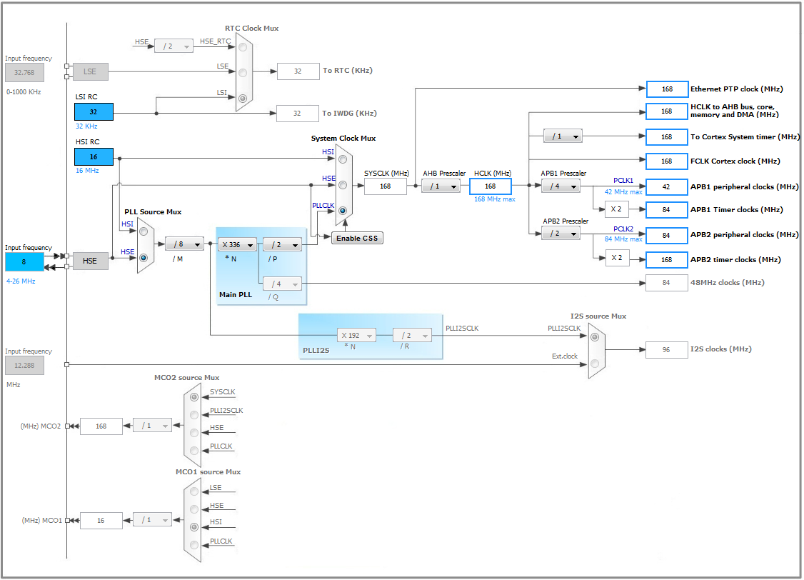
On the Clock Configuration tab, adjust the frequency, as in the picture below.
Next, on the Configuration tab, configure the USART ports. We will work with them in DMA mode. We have two USART ports, one we will use for transmitting and receiving data via PPP protocol, the second one for logging. For them to work, we need to configure DMA on RX and TX for both ports. For all the legs of the DMA setting, priority is set to “Medium”. For USART2 leg RX set the mode "Circular". The remaining settings are left by default.
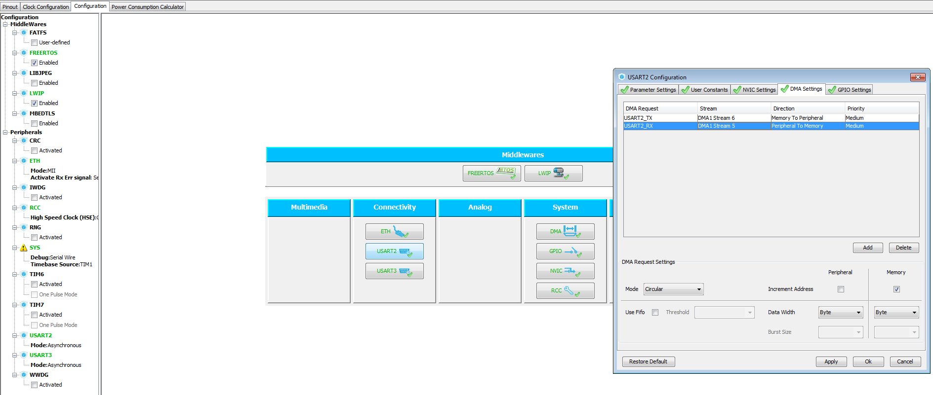
You will also need to enable a global interrupt for both ports on the “NVIC Settings” tab.
This completes the initial setup of the project in STM32CubeMX. Save the project file and do code generation for System Workbench for STM32.
Now let's verify that the unloaded code compiles and runs. To do this, in the main.c file in the “StartDefaultTask” function, we replace the body of the for (;;) infinite loop with the code for turning on and off the LEDs.
It should turn out like this:
We compile the firmware and look. On the board should blink all four LEDs.
Our next task is to check the correct operation of our USART.
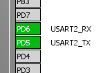
The first thing we need to do is connect our FT232 to discovery. To do this, look at what legs are separated USART interfaces. I have this PD6 and PD5 for USART2_RX and USART2_TX respectively.
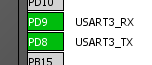
As well as PD9 and PD8 for USART3_RX and USART3_TX respectively.
In addition, we need a leg GND.
We find these pins on the board and connect to the FT232 pins while the GND pin on the board can be anything, the RX pin on the board should be connected to the TX pin on FT232, and the TX pin on the board should be connected to the RX pin on FT232. The remaining conclusions are not used.
It remains to connect our FT232 to the USB ports of the computer, and also to connect the discovery board via the miniUSB connector to the computer (not to be confused with microUSB).
After connecting the FT232, the main OS will install drivers for them, after which these devices will need to be forwarded to the Windows guest on the virtual machine.
Now add the program code that is needed for our USART to work. To do this, we will add four files: usart.h, usart.c, logger.h, logger.c.
File Contents:
usart.h file
usart.c file
logger.h file
logger.c file
Usart we need to transfer and receive data on usart2. It will be our main interface to communicate with the PPP server.
Logger we need to implement logging, by sending messages to the terminal. The void usart_Open (void) function forms a queue and starts the task of servicing this queue. This function must be performed before you start working with USART. Then everything is simple, the bool usart_Send function (char * bArray, int size_bArray) sends data to the port, and
uint16_t usart_Recv (char * bArray, uint16_t maxLength) gets it from the queue, in which the function void usart_rxTask (void) has kindly added them.
It is still easier for the logger, there is no need to receive data there, therefore neither a queue nor a queue maintenance task is needed.
To the beginning of the main.h file You need to add several defines describing the bool type, which is absent in C.
Now it's time to check the performance of the received code. To do this, in the main.c file , change the code of the task “StartDefaultTask” already known to us
In addition, you need to give more memory to the stack of our task. To do this, in the osThreadDef () function call, the main.c file, you need 128 to fix it at 128 * 10 to make it like this:
Compile and flash. The LEDs blink in the same way as in the previous task.
To see the result of our work, you need to run the Terminal program in our virtual machine. One copy of the program for the logging port, the second for the main one. Check in the device manager which port numbers were assigned to your FT232. If numbers more than 10 have been assigned, reassign.
When starting the second copy of the program, an error may occur, close the window with an error and continue working with the program.
For both ports, we establish a connection at 115200 baud, data bits - 8, parity - none, stop bits - 1, handshaking - none.
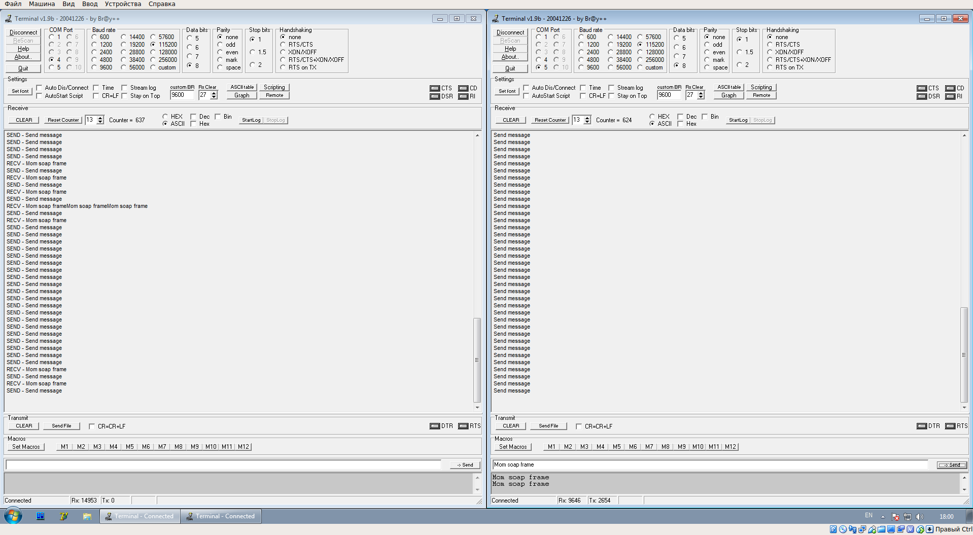
If you did everything correctly, then the message “Send message” will be sent to usart2 in the terminal window. In the terminal window for the logger, the same message will be duplicated only with the “SEND -” prefix.
If in the terminal window for usart2 you type some text in the “Send” field and press the corresponding button to the right of this field, you will see in the window of the logger the same message with the prefix “RECV -”
In the picture below: on the left - the logger, on the right - usart2.
As part of this task, we will raise the PPP connection. First of all, enable the use of PPP, change the PPP_SUPPORT define value in the ppp_opts.h file to 1. Then we override the required defaults in the lwipopts.h file,
At the same time, old defines should be commented out.
Now we change the lwip.c file, insert the following code into the “/ * USER CODE BEGIN 0 * /” block:
Then, in the MX_LWIP_Init () function, in the “/ * USER CODE BEGIN 3 * /” block, we add the pppConnect () function call.
In addition, you need to increase the heap size, for this you need to comment out define configTOTAL_HEAP_SIZE in the FreeRTOSConfig.h file, and at the end of the file, in the / * USER CODE BEGIN Defines * / block, declare it with a new value.
And also in the usart.c file, change the Q_USART2_SIZE defaults value to 2048.
Connection setup begins with the MX_LWIP_Init function () it was created automatically; we just added the pppConnect () function call to it. This function runs tasks serving a PPPOS connection. The pppos_create () functions need to pass the addresses of the functions that will serve the sending of messages and the output of information about the change in the connection status. For us, these are the functions ppp_output_cb () and ppp_link_status_cb (), respectively. In addition, the task of servicing received messages will be launched in the pppConnect () function. At the end of its work, the pppConnect () function will wait for the connection to the server to be established, after which it will complete its work.
Work with the network will be carried out at a higher level, as soon as LWIP decides to send a message to the network, the ppp_output_cb () function will be automatically called. The response from the network will be received by the PppGetTask () function, as part of the task of servicing incoming messages, and transferred to the LWIP subsoil. If the connection status changes, the ppp_link_status_cb () function will be automatically called.
Finally, we change the StartDefaultTask task. Now it should look like this:
Done, you can compile and flash.
At this point, you need to start the PPP server. To do this, you first need to deploy a virtual machine with Linux OS. I used Ubuntu 16.04 x32. After installing the operating system, you need to configure the use of the COM port.
In this part, we do not need a virtual machine with Windows, we can safely turn it off. Both FT232 connect to Linux.
In Linux, before you start working with a COM port, you must allow the user to use it. To do this, run the following command:
where USERNAME is the name of the current user.
To view the available ports in the COM system, run the following command:
We see that there are two ttyUSB ports on the system. We can not immediately tell which one is logger, and which usart2. You just need to check them one by one.
First, execute commands to read from one port:
then from another:
Where we see such a picture is the logger.
You can leave this window, it will not bother us.
Next you need to allow packets sent from our board to leave the limits of your subnet. To do this, you need to configure iptables. Perform the following steps:
1. Open a new console window
2. You need to know your ip and the name of the network interface (execute the ifconfig command )
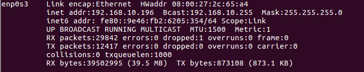
3. Run the nat configuration commands
where enp0s3 is the name of the network interface
192.168.10.196 is your IP address
/ proc / sys / net / ipv4 / is the path to the corresponding file.
These commands can be rewritten into a batch file and executed each time before starting the PPP server. You can add to the autorun, but I did not.
Now we are ready to start the server, it remains only to create a configuration file. I called it " pppd.conf ", I suggest using the following settings:
We rewrite the settings to a file and then we can start the server. This is done with the command sudo pppd file ./pppd.conf
The PPPD server must be started before the discovery starts, so after the PPPD start, you must click on the “Reset” button located on the board.
If you did everything correctly, you will see the following picture:
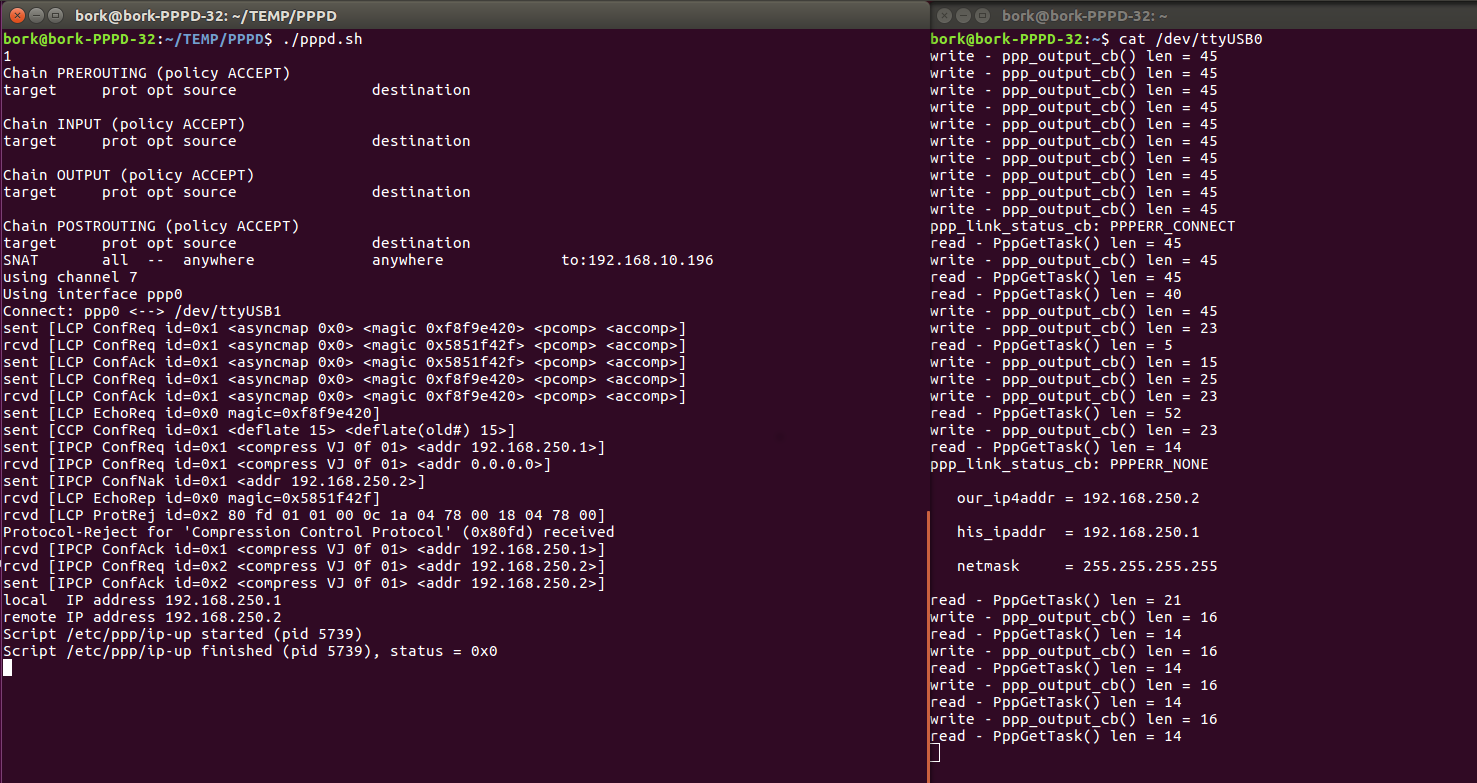
pppd running on the left, logger on the right.
At this stage we will need both virtualka. Linux for pppd and Windows for receiving a package. To simplify the task, you need both machines to be on the same subnet, the ideal solution is to specify the Network Bridge connection in the VirtualBox network settings for both machines, and disable the firewall in Windows.
We start the virtual machines and configure the ppp connection of the discovery board with pppd. On Windows, we get the IP address of the machine (ipconfig command), I got it 192.168.10.97.
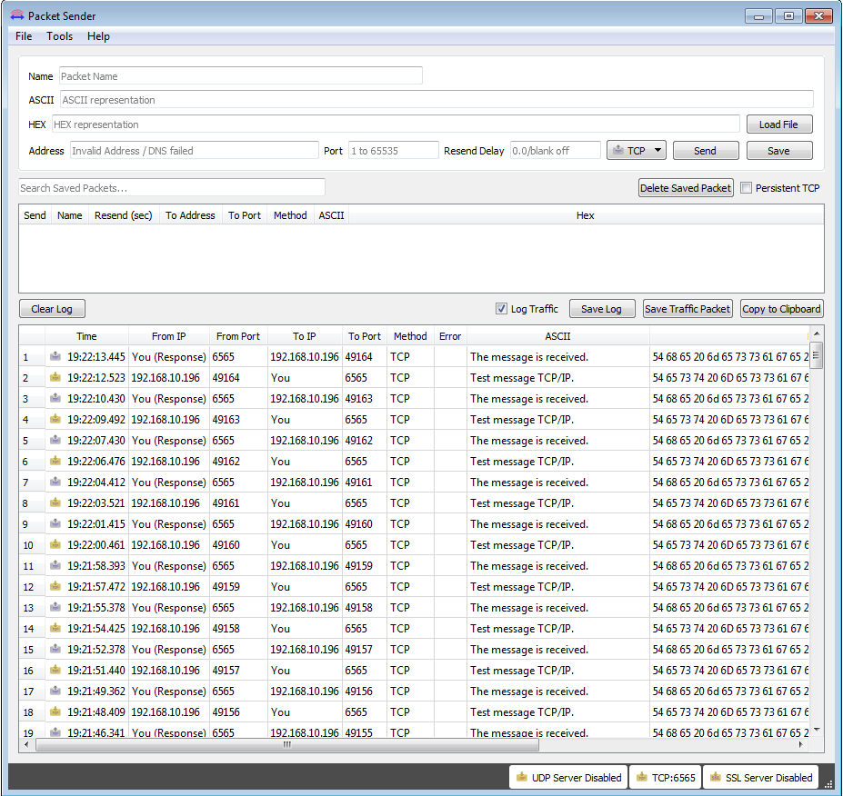
We start the Packet Sender and configure it as follows:

Now we will again change the StartDefaultTask task in the main.c file .
The value of the addr variable is the Windows address of the machine, the port number is 6565. The
message sent is “Test message TCP / IP.”, The answer is “The message is received.”
Here you can see that PPP functions are not directly used to send and receive messages. All work happens at a higher level, and our functions are called automatically.
Compile and flash.
The result of the connection with pppd is visible on the Linux machine:
The received requests and sent responses can be seen in the Packet Sender program on the Windows machine:
Well, that's all, the package we sent from the discovery board went to the COM port, got to the pppd server, was sent to port 6565 of the Windows machine, there it was successfully received, in response to it another package was sent that passed this way in the opposite direction and was successfully adopted on the board. With the same success you can send messages to any machine on the Internet.
→ The complete project code can be downloaded here.
In the process of solving the task set before me, I encountered some difficulties, one of which is insufficient, in my opinion, coverage of issues related to PPPoS on the Internet. With this post I will try to close the indicated gap, as far as my modest knowledge will allow.
This article describes how to create a project for System Workbench for STM32 from scratch. Shows an example of working with a UART. There are code examples for implementing PPP. And of course, an example of sending a message to a nearby computer.
Introduction
PPP (English Point-to-Point Protocol) is a two-point data link protocol of the OSI network model. Usually used to establish a direct connection between two network nodes, and it can provide connection authentication, encryption and data compression. Used on many types of physical networks: null-modem cable, telephone line, cellular communication, etc.
Often there are subspecies of the PPP protocol, such as Point-to-Point Protocol over Ethernet (PPPoE), used to connect via Ethernet, and sometimes via DSL; and Point-to-Point Protocol over ATM (PPPoA), which is used to connect via ATM Adaptation Layer 5 (AAL5), which is the main PPPoE alternative to DSL.
PPP is a whole family of protocols: link control protocol (LCP), network control protocol (NCP), authentication protocols (PAP, CHAP), multichannel PPP protocol (MLPPP).
From Wikipedia .
Training
To solve the problem we need:
Iron:
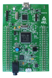
- Debug board stm32f4_discovery:
- USB - miniUSB adapter for connecting the board to the computer.
- Two USBtoUART FT232 Adapters:

- Also, two USB extension cables are useful, not necessarily, but just convenient.
Soft:
- VirtualBox virtual machine. You can download it here . Also download and install the Extension Pack for VirtualBox.
- Two installation discs with Windows and Linux operating systems. Windows we take here , Linux here .
After installing the OS, you will need to install the additions of the guest OS. For the task, we only need 32x systems, you can not fool with the inclusion of virtualization. - For Windows, we will need a program capable of accepting requests and responding to them via TCP / IP, well, and a terminal program for working with a COM port. PacketSender download here (click on "No thanks, just let me download."), The terminal is here . In addition, we need STM32CubeMX for the initial setup of the project. Downloading from st.com (after registration, the link will be sent to the email).
- On the main OS we put System Workbench for STM32. Downloading from here (registration is required).
Stage 1. Creating a project
First of all, open the STM32CubeMX and create a new project there for our stm32f4-discovery card. Turn on RCC, Ethernet (ETH), SYS, USART2, USART3, then turn on FREERTOS and LWIP.
For the diagnosis, we need the LEDs on the board. By this, we configure the legs of the PD12-PD15 as GPIO_Output.
On the Clock Configuration tab, adjust the frequency, as in the picture below.
Next, on the Configuration tab, configure the USART ports. We will work with them in DMA mode. We have two USART ports, one we will use for transmitting and receiving data via PPP protocol, the second one for logging. For them to work, we need to configure DMA on RX and TX for both ports. For all the legs of the DMA setting, priority is set to “Medium”. For USART2 leg RX set the mode "Circular". The remaining settings are left by default.
You will also need to enable a global interrupt for both ports on the “NVIC Settings” tab.
This completes the initial setup of the project in STM32CubeMX. Save the project file and do code generation for System Workbench for STM32.
Implementation
Now let's verify that the unloaded code compiles and runs. To do this, in the main.c file in the “StartDefaultTask” function, we replace the body of the for (;;) infinite loop with the code for turning on and off the LEDs.
It should turn out like this:
/* StartDefaultTask function */voidStartDefaultTask(voidconst * argument){
  /* init code for LWIP */
  MX_LWIP_Init();
  /* USER CODE BEGIN 5 *//* Infinite loop */for(;;)
  {
    HAL_GPIO_WritePin(GPIOD, GPIO_PIN_12|GPIO_PIN_13|GPIO_PIN_14|GPIO_PIN_15, GPIO_PIN_SET);
    osDelay(1000);
    HAL_GPIO_WritePin(GPIOD, GPIO_PIN_12|GPIO_PIN_13|GPIO_PIN_14|GPIO_PIN_15, GPIO_PIN_RESET);
    osDelay(1000);
  }
  /* USER CODE END 5 */
}
We compile the firmware and look. On the board should blink all four LEDs.
Stage 2. Work with USART
Our next task is to check the correct operation of our USART.
The first thing we need to do is connect our FT232 to discovery. To do this, look at what legs are separated USART interfaces. I have this PD6 and PD5 for USART2_RX and USART2_TX respectively.
As well as PD9 and PD8 for USART3_RX and USART3_TX respectively.
In addition, we need a leg GND.
We find these pins on the board and connect to the FT232 pins while the GND pin on the board can be anything, the RX pin on the board should be connected to the TX pin on FT232, and the TX pin on the board should be connected to the RX pin on FT232. The remaining conclusions are not used.
It remains to connect our FT232 to the USB ports of the computer, and also to connect the discovery board via the miniUSB connector to the computer (not to be confused with microUSB).
After connecting the FT232, the main OS will install drivers for them, after which these devices will need to be forwarded to the Windows guest on the virtual machine.
Now add the program code that is needed for our USART to work. To do this, we will add four files: usart.h, usart.c, logger.h, logger.c.
File Contents:
usart.h file
#ifndef _USART_#define _USART_#include"stm32f4xx_hal.h"voidusart_Open(void);
boolusart_Send(char* bArray, int size_bArray);
uint16_t usart_Recv(char* bArray, uint16_t maxLength);
#endif/* _USART_ */
usart.c file
#include"usart.h"#include"logger.h"#include"cmsis_os.h"#define Q_USART2_SIZE 200
xQueueHandle g_qUsart;
osThreadId g_usart_rxTaskHandle;
extern UART_HandleTypeDef huart2;
voidusart_rxTask(void);
uint8_t bGet[Q_USART2_SIZE] = {0};
uint16_t g_tail = 0;
voidusart_Open(void){
	g_qUsart = xQueueCreate( Q_USART2_SIZE, sizeof( unsignedchar ) );
	osThreadDef(usart_rxTask_NAME, usart_rxTask, osPriorityNormal, 0, Q_USART2_SIZE/4+128);
	g_usart_rxTaskHandle = osThreadCreate(osThread(usart_rxTask_NAME), NULL);
	HAL_UART_Receive_DMA(&huart2, bGet, Q_USART2_SIZE);
}
voidusart_rxTask(void){
	for(;;)
	{
		uint16_t length = Q_USART2_SIZE - huart2.hdmarx->Instance->NDTR;
		while(length - g_tail)
		{
			uint8_t tmp = bGet[g_tail];
			xQueueSendToBack( g_qUsart, &tmp, 100 );
			g_tail++;
			if (g_tail == Q_USART2_SIZE)
				g_tail = 0;
		}
	}
}
boolusart_Send(char* bArray, int size_bArray){
	HAL_StatusTypeDef status;
	status = HAL_UART_Transmit_DMA(&huart2, bArray, size_bArray);
	while (HAL_UART_GetState(&huart2) != HAL_UART_STATE_READY)
	{
		if (HAL_UART_GetState(&huart2) == HAL_UART_STATE_BUSY_RX)
			break;
		osDelay(1);
	}
	if (status == HAL_OK)
		returntrue;
	returnfalse;
}
uint16_t usart_Recv(char* bArray, uint16_t maxLength)
{
	uint8_t tmp = 0;
	uint16_t length = 0;
	while(uxQueueMessagesWaiting(g_qUsart))
	{
		xQueueReceive( g_qUsart, &tmp, 100 );
		bArray[length] = tmp;
		length++;
		if (length >= maxLength)
			break;
	}
	return length;
}
logger.h file
#ifndef _LOGGER_#define _LOGGER_voidlogger(constchar *format, ...);
#endif/* _LOGGER_ */
logger.c file
#include"logger.h"#include"stm32f4xx_hal.h"#include<stdarg.h>extern UART_HandleTypeDef huart3;
#define MAX_STRING_SIZE 1024HAL_StatusTypeDef logger_Send(char* bArray, uint32_t size_bArray){
	HAL_StatusTypeDef status;
	for(int i=0;i<5;i++)
	{
		status = HAL_UART_Transmit_DMA(&huart3, bArray, size_bArray);
		if (status == HAL_OK)
			break;
		osDelay(2);
	}
	while (HAL_UART_GetState(&huart3) != HAL_UART_STATE_READY)
	{
		osDelay(1);
	}
	return status;
}
voidlogger(constchar *format, ...){
		char buffer[MAX_STRING_SIZE];
		va_list args;
		va_start (args, format);
		vsprintf(buffer, format, args);
		va_end(args);
		buffer[MAX_STRING_SIZE-1]=0;
		logger_Send(buffer, strlen(buffer));
}
Usart we need to transfer and receive data on usart2. It will be our main interface to communicate with the PPP server.
Logger we need to implement logging, by sending messages to the terminal. The void usart_Open (void) function forms a queue and starts the task of servicing this queue. This function must be performed before you start working with USART. Then everything is simple, the bool usart_Send function (char * bArray, int size_bArray) sends data to the port, and
uint16_t usart_Recv (char * bArray, uint16_t maxLength) gets it from the queue, in which the function void usart_rxTask (void) has kindly added them.
It is still easier for the logger, there is no need to receive data there, therefore neither a queue nor a queue maintenance task is needed.
To the beginning of the main.h file You need to add several defines describing the bool type, which is absent in C.
/* USER CODE BEGIN Includes */typedefunsignedcharbool;
#define true 1#define false 0/* USER CODE END Includes */
Now it's time to check the performance of the received code. To do this, in the main.c file , change the code of the task “StartDefaultTask” already known to us
/* USER CODE BEGIN 4 */#include"usart.h"#include"logger.h"#define MAX_MESSAGE_LENGTH 100/* USER CODE END 4 *//* StartDefaultTask function */voidStartDefaultTask(voidconst * argument){
  /* init code for LWIP */
  MX_LWIP_Init();
  /* USER CODE BEGIN 5 */
  usart_Open();
  /* Infinite loop */uint8_t send[] = "Send message\r\n";
  uint8_t recv[MAX_MESSAGE_LENGTH] = {0};
  uint16_t recvLength = 0;
  for(;;)
  {
	HAL_GPIO_WritePin(GPIOD, GPIO_PIN_12|GPIO_PIN_13|GPIO_PIN_14|GPIO_PIN_15, GPIO_PIN_SET);
	osDelay(1000);
	HAL_GPIO_WritePin(GPIOD, GPIO_PIN_12|GPIO_PIN_13|GPIO_PIN_14|GPIO_PIN_15, GPIO_PIN_RESET);
	osDelay(1000);
	if (usart_Send(send, sizeof(send)-1))
	  logger("SEND - %s", send);
	recvLength = usart_Recv(recv, MAX_MESSAGE_LENGTH-1);
	if (recvLength)
	{
	  recv[recvLength] = 0;
	  logger("RECV - %s\r\n", recv);
	}
  }
  /* USER CODE END 5 */
}
In addition, you need to give more memory to the stack of our task. To do this, in the osThreadDef () function call, the main.c file, you need 128 to fix it at 128 * 10 to make it like this:
osThreadDef(defaultTask, StartDefaultTask, osPriorityNormal, 0, <b>128*10</b>);Compile and flash. The LEDs blink in the same way as in the previous task.
To see the result of our work, you need to run the Terminal program in our virtual machine. One copy of the program for the logging port, the second for the main one. Check in the device manager which port numbers were assigned to your FT232. If numbers more than 10 have been assigned, reassign.
When starting the second copy of the program, an error may occur, close the window with an error and continue working with the program.
For both ports, we establish a connection at 115200 baud, data bits - 8, parity - none, stop bits - 1, handshaking - none.
If you did everything correctly, then the message “Send message” will be sent to usart2 in the terminal window. In the terminal window for the logger, the same message will be duplicated only with the “SEND -” prefix.
If in the terminal window for usart2 you type some text in the “Send” field and press the corresponding button to the right of this field, you will see in the window of the logger the same message with the prefix “RECV -”
In the picture below: on the left - the logger, on the right - usart2.
Stage 3. Getting Started with PPP
As part of this task, we will raise the PPP connection. First of all, enable the use of PPP, change the PPP_SUPPORT define value in the ppp_opts.h file to 1. Then we override the required defaults in the lwipopts.h file,
/* USER CODE BEGIN 1 */#define MEMP_NUM_SYS_TIMEOUT 8#define CHECKSUM_GEN_IP 1#define CHECKSUM_GEN_TCP 1/* USER CODE END 1 */At the same time, old defines should be commented out.
Now we change the lwip.c file, insert the following code into the “/ * USER CODE BEGIN 0 * /” block:
/* USER CODE BEGIN 0 */#include"usart.h"#include"pppos.h"#include"sio.h"#include"dns.h"#include"ppp.h"static ppp_pcb *ppp;
structnetifpppos_netif;voidPppGetTask(voidconst * argument){
  uint8_t recv[2048];
  uint16_t length = 0;
  for(;;)
  {
	length=usart_Recv(recv, 2048);
	if (length)
	{
		pppos_input(ppp, recv, length);
		logger("read - PppGetTask() len = %d\n", length);
	}
	osDelay(10);
  }
}
#include"ip4_addr.h"#include"dns.h"staticvoidppp_link_status_cb(ppp_pcb *pcb, int err_code, void *ctx){
		structnetif *pppif = ppp_netif(pcb);
		LWIP_UNUSED_ARG(ctx);
		switch(err_code)
		{
			case PPPERR_NONE:               /* No error. */
			{
				logger("ppp_link_status_cb: PPPERR_NONE\n\r");
				logger("   our_ip4addr = %s\n\r", ip4addr_ntoa(netif_ip4_addr(pppif)));
				logger("   his_ipaddr  = %s\n\r", ip4addr_ntoa(netif_ip4_gw(pppif)));
				logger("   netmask     = %s\n\r", ip4addr_ntoa(netif_ip4_netmask(pppif)));
			}
			break;
			case PPPERR_PARAM:             /* Invalid parameter. */
					logger("ppp_link_status_cb: PPPERR_PARAM\n");
					break;
			case PPPERR_OPEN:              /* Unable to open PPP session. */
					logger("ppp_link_status_cb: PPPERR_OPEN\n");
					break;
			case PPPERR_DEVICE:            /* Invalid I/O device for PPP. */
					logger("ppp_link_status_cb: PPPERR_DEVICE\n");
					break;
			case PPPERR_ALLOC:             /* Unable to allocate resources. */
					logger("ppp_link_status_cb: PPPERR_ALLOC\n");
					break;
			case PPPERR_USER:              /* User interrupt. */
					logger("ppp_link_status_cb: PPPERR_USER\n");
					break;
			case PPPERR_CONNECT:           /* Connection lost. */
					logger("ppp_link_status_cb: PPPERR_CONNECT\n");
					break;
			case PPPERR_AUTHFAIL:          /* Failed authentication challenge. */
					logger("ppp_link_status_cb: PPPERR_AUTHFAIL\n");
					break;
			case PPPERR_PROTOCOL:          /* Failed to meet protocol. */
					logger("ppp_link_status_cb: PPPERR_PROTOCOL\n");
					break;
			case PPPERR_PEERDEAD:          /* Connection timeout. */
					logger("ppp_link_status_cb: PPPERR_PEERDEAD\n");
					break;
			case PPPERR_IDLETIMEOUT:       /* Idle Timeout. */
					logger("ppp_link_status_cb: PPPERR_IDLETIMEOUT\n");
					break;
			case PPPERR_CONNECTTIME:       /* PPPERR_CONNECTTIME. */
					logger("ppp_link_status_cb: PPPERR_CONNECTTIME\n");
					break;
			case PPPERR_LOOPBACK:          /* Connection timeout. */
					logger("ppp_link_status_cb: PPPERR_LOOPBACK\n");
					break;
			default:
					logger("ppp_link_status_cb: unknown errCode %d\n", err_code);
					break;
		}
}
// Callback used by ppp connectionstatic u32_t ppp_output_cb(ppp_pcb *pcb, u8_t *data, u32_t len, void *ctx){
	LWIP_UNUSED_ARG(pcb);
	LWIP_UNUSED_ARG(ctx);
	if (len > 0)
	{
		if (!usart_Send(data, len))
				return0x05;
	}
	logger("write - ppp_output_cb() len = %d\n", len);
	return len;
}
voidpppConnect(void){
	ppp = pppos_create(&pppos_netif, ppp_output_cb, ppp_link_status_cb, NULL);
	ppp_set_default(ppp);
	osThreadId PppGetTaskHandle;
	osThreadDef(PPP_GET_TASK_NAME, PppGetTask, osPriorityNormal, 0, 128*10);
	PppGetTaskHandle = osThreadCreate(osThread(PPP_GET_TASK_NAME), NULL);
	err_t err = ppp_connect(ppp,0);
	if (err == ERR_ALREADY)
	{
		logger("Connected successfully");
	}
	for(int i=0;i<40;i++)
	{
		osDelay(500);
		if (ppp->phase >= PPP_PHASE_RUNNING)
			break;
	}
}
/* USER CODE END 0 */
Then, in the MX_LWIP_Init () function, in the “/ * USER CODE BEGIN 3 * /” block, we add the pppConnect () function call.
In addition, you need to increase the heap size, for this you need to comment out define configTOTAL_HEAP_SIZE in the FreeRTOSConfig.h file, and at the end of the file, in the / * USER CODE BEGIN Defines * / block, declare it with a new value.
/* USER CODE BEGIN Defines *//* Section where parameter definitions can be added (for instance, to override default ones in FreeRTOS.h) */#define configTOTAL_HEAP_SIZE ((size_t)1024*30)/* USER CODE END Defines */And also in the usart.c file, change the Q_USART2_SIZE defaults value to 2048.
Connection setup begins with the MX_LWIP_Init function () it was created automatically; we just added the pppConnect () function call to it. This function runs tasks serving a PPPOS connection. The pppos_create () functions need to pass the addresses of the functions that will serve the sending of messages and the output of information about the change in the connection status. For us, these are the functions ppp_output_cb () and ppp_link_status_cb (), respectively. In addition, the task of servicing received messages will be launched in the pppConnect () function. At the end of its work, the pppConnect () function will wait for the connection to the server to be established, after which it will complete its work.
Work with the network will be carried out at a higher level, as soon as LWIP decides to send a message to the network, the ppp_output_cb () function will be automatically called. The response from the network will be received by the PppGetTask () function, as part of the task of servicing incoming messages, and transferred to the LWIP subsoil. If the connection status changes, the ppp_link_status_cb () function will be automatically called.
Finally, we change the StartDefaultTask task. Now it should look like this:
voidStartDefaultTask(voidconst * argument){
  /* init code for LWIP *///  MX_LWIP_Init();/* USER CODE BEGIN 5 */
  usart_Open();
  MX_LWIP_Init();
  /* Infinite loop */for(;;)
  {
	HAL_GPIO_WritePin(GPIOD, GPIO_PIN_12|GPIO_PIN_13|GPIO_PIN_14|GPIO_PIN_15, GPIO_PIN_SET);
	osDelay(1000);
	HAL_GPIO_WritePin(GPIOD, GPIO_PIN_12|GPIO_PIN_13|GPIO_PIN_14|GPIO_PIN_15, GPIO_PIN_RESET);
	osDelay(1000);
  }
  /* USER CODE END 5 */
}
Done, you can compile and flash.
At this point, you need to start the PPP server. To do this, you first need to deploy a virtual machine with Linux OS. I used Ubuntu 16.04 x32. After installing the operating system, you need to configure the use of the COM port.
In this part, we do not need a virtual machine with Windows, we can safely turn it off. Both FT232 connect to Linux.
In Linux, before you start working with a COM port, you must allow the user to use it. To do this, run the following command:
sudo addgroup USERNAME dialoutwhere USERNAME is the name of the current user.
To view the available ports in the COM system, run the following command:
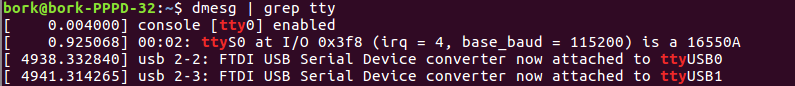
dmesg | grep ttyWe see that there are two ttyUSB ports on the system. We can not immediately tell which one is logger, and which usart2. You just need to check them one by one.
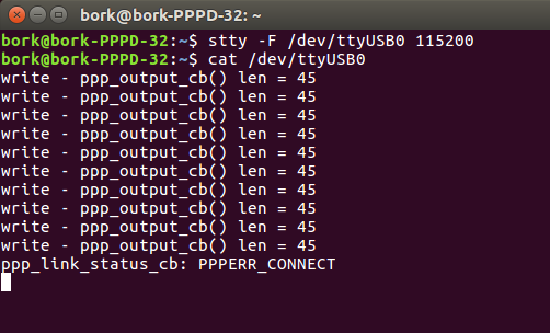
First, execute commands to read from one port:
stty -F /dev/ttyUSB0 115200
cat /dev/ttyUSB0
then from another:
stty -F /dev/ttyUSB1 115200
cat /dev/ttyUSB1
Where we see such a picture is the logger.
You can leave this window, it will not bother us.
Next you need to allow packets sent from our board to leave the limits of your subnet. To do this, you need to configure iptables. Perform the following steps:
1. Open a new console window
2. You need to know your ip and the name of the network interface (execute the ifconfig command )
3. Run the nat configuration commands
sudo echo1 | sudo tee -a /proc/sys/net/ipv4/ip_forward > /dev/null
sudo echo1 | sudo tee -a /proc/sys/net/ipv4/ip_dynaddr > /dev/null
sudo iptables -F FORWARD
sudo iptables -F -t nat
sudo iptables -t nat -A POSTROUTING -o enp0s3 -j SNAT --to-source 192.168.10.196
sudo iptables -t nat -L
where enp0s3 is the name of the network interface
192.168.10.196 is your IP address
/ proc / sys / net / ipv4 / is the path to the corresponding file.
These commands can be rewritten into a batch file and executed each time before starting the PPP server. You can add to the autorun, but I did not.
Now we are ready to start the server, it remains only to create a configuration file. I called it " pppd.conf ", I suggest using the following settings:
nodetach
noauth
passive
localdebuglock192.168.250.1:192.168.250.2
/dev/ttyUSB1
115200
lcp-echo-interval10
lcp-echo-failure 1
cdtrcts
We rewrite the settings to a file and then we can start the server. This is done with the command sudo pppd file ./pppd.conf
The PPPD server must be started before the discovery starts, so after the PPPD start, you must click on the “Reset” button located on the board.
If you did everything correctly, you will see the following picture:
pppd running on the left, logger on the right.
Stage 4. We send a bag
At this stage we will need both virtualka. Linux for pppd and Windows for receiving a package. To simplify the task, you need both machines to be on the same subnet, the ideal solution is to specify the Network Bridge connection in the VirtualBox network settings for both machines, and disable the firewall in Windows.
We start the virtual machines and configure the ppp connection of the discovery board with pppd. On Windows, we get the IP address of the machine (ipconfig command), I got it 192.168.10.97.
We start the Packet Sender and configure it as follows:
Now we will again change the StartDefaultTask task in the main.c file .
/* USER CODE BEGIN 4 */#include"logger.h"#include"sockets.h"typedefuint32_t SOCKET;
/* USER CODE END 4 *//* StartDefaultTask function */voidStartDefaultTask(voidconst * argument){
  /* init code for LWIP *///  MX_LWIP_Init();/* USER CODE BEGIN 5 */
  usart_Open();
  MX_LWIP_Init();
  /* Infinite loop */uint8_t sendStr[]="Test message TCP/IP.";
  uint8_t resvStr[100]={0};
  int     resvLength = 0;
  structsockaddr_insockAddr;
  sockAddr.sin_family = AF_INET;
  sockAddr.sin_port   = htons( 6565 );
  uint32_t addr = inet_addr("192.168.10.97");
  sockAddr.sin_addr.s_addr = addr;
  SOCKET socket = NULL;
  int nError = 0;
  /* Infinite loop */for(;;)
  {
	HAL_GPIO_WritePin(GPIOD, GPIO_PIN_12|GPIO_PIN_13|GPIO_PIN_14|GPIO_PIN_15, GPIO_PIN_SET);
	osDelay(1000);
	HAL_GPIO_WritePin(GPIOD, GPIO_PIN_12|GPIO_PIN_13|GPIO_PIN_14|GPIO_PIN_15, GPIO_PIN_RESET);
	osDelay(1000);
	socket = socket( AF_INET, SOCK_STREAM, 0 );
	nError = connect( socket, (struct sockaddr*)&sockAddr, sizeof(sockAddr) );
	if ( nError ==  0 )
	{
	  nError = send( socket, sendStr, sizeof(sendStr)-1, 0 );
	  if ( nError <  0 )
		  logger("SEND ERROR %d\n", nError);
	  else
	  {
		  logger("SEND - %s\n", sendStr);
		  resvLength = 0;
		  while(resvLength < 1)
			  resvLength = lwip_recv( socket, resvStr, sizeof(resvStr), MSG_WAITALL);
		  resvStr[resvLength]=0;
		  logger("GET - %s\n", resvStr);
	  }
	  lwip_close(socket);
	}
	else
	  logger("CONNECT ERROR %d\n", nError);
  }
  /* USER CODE END 5 */
}
The value of the addr variable is the Windows address of the machine, the port number is 6565. The
message sent is “Test message TCP / IP.”, The answer is “The message is received.”
Here you can see that PPP functions are not directly used to send and receive messages. All work happens at a higher level, and our functions are called automatically.
Compile and flash.
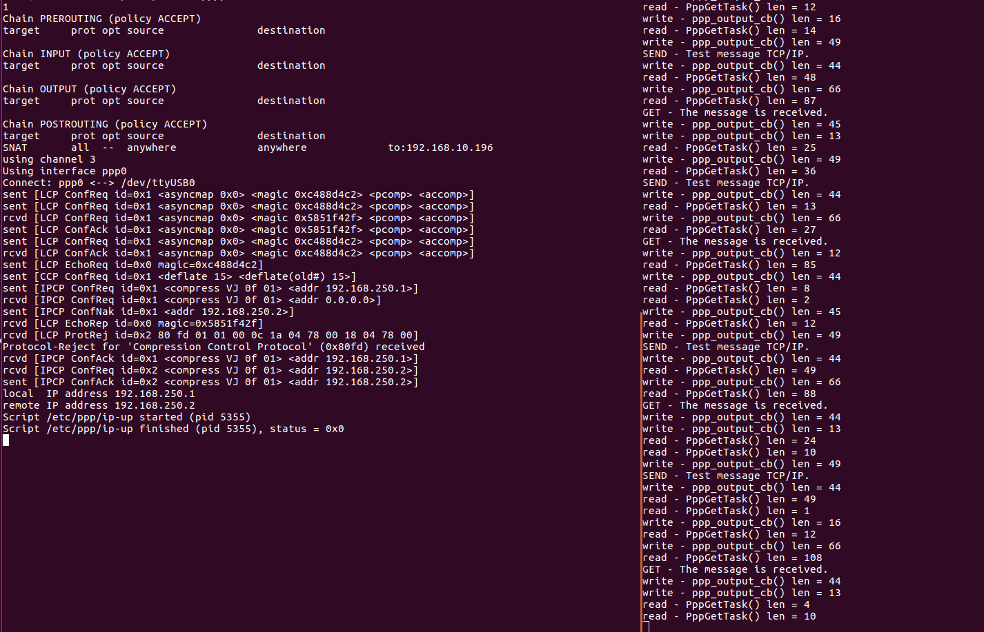
The result of the connection with pppd is visible on the Linux machine:
The received requests and sent responses can be seen in the Packet Sender program on the Windows machine:
Well, that's all, the package we sent from the discovery board went to the COM port, got to the pppd server, was sent to port 6565 of the Windows machine, there it was successfully received, in response to it another package was sent that passed this way in the opposite direction and was successfully adopted on the board. With the same success you can send messages to any machine on the Internet.
→ The complete project code can be downloaded here.