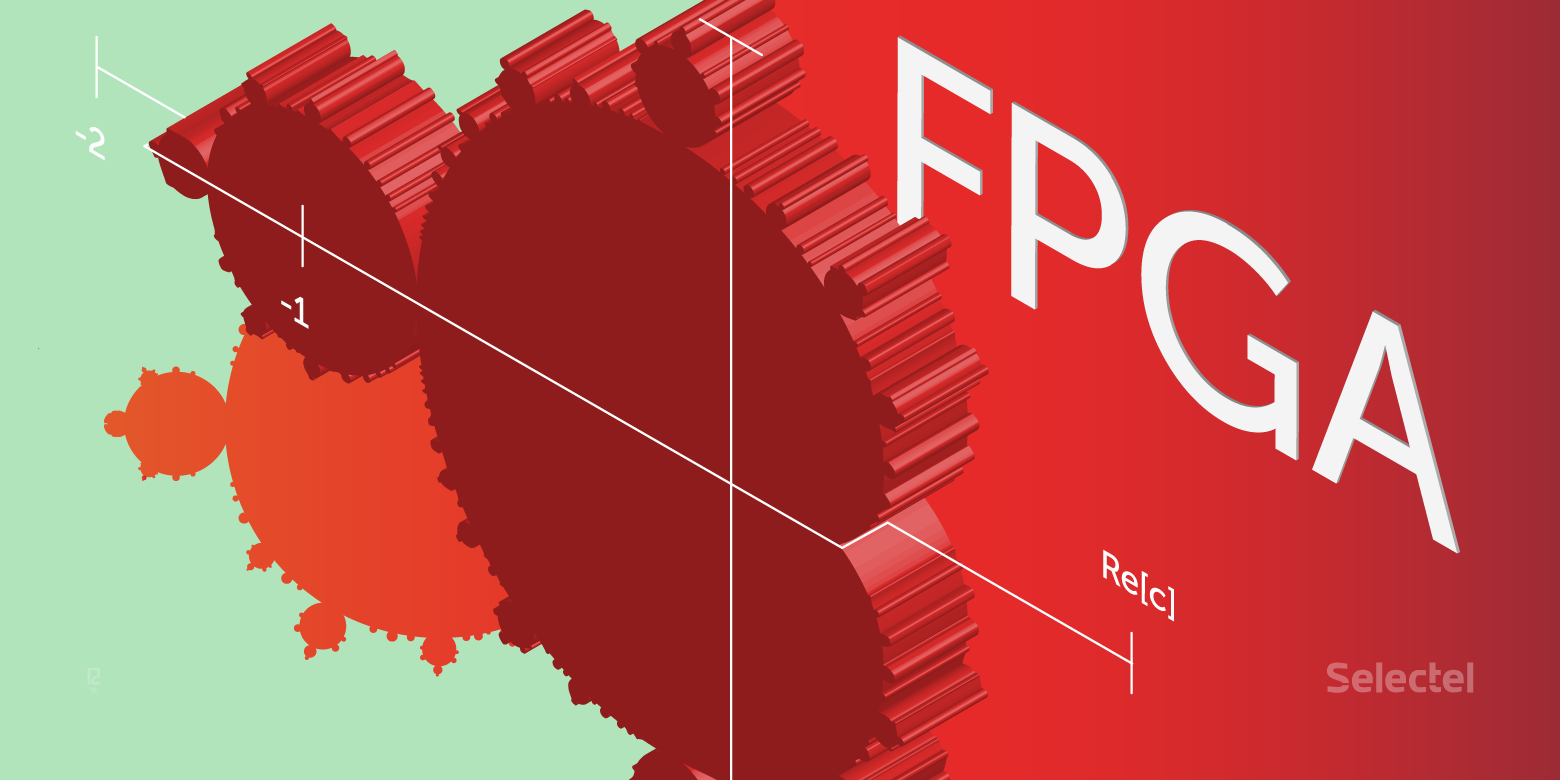
FPGA accelerator programming example
Not so long ago, we talked about the new Selectel service - high-performance cloud computing on FPGA accelerators . In a new article on this topic, we consider an example of programming an FPGA to build a Mandelbrot set, a well-known mathematical algorithm for rendering fractal images. The article used material from the site Euler Project .
- Instead of the preface
- Looking ahead: try FPGA at work
- About the OpenCL standard for FPGA programming
- OpenCL environment for creating executable code
- Get to the point: building a fractal
- Conclusion
Instead of the preface
First, a few terms. A computer system with an FPGA accelerator - as a rule, this is a PCIe adapter with an FPGA chip as part of an x64 server. The accelerator takes on a separate resource-intensive task, in which parallel computations can be used and performs it many orders of magnitude faster than the x64 processor, unloading it and increasing the performance of the entire computing system. For example, a calculation cycle with 100 thousand repetitions can be performed on an FPGA in just one pass instead of sequentially running 100 thousand times on a classic x64 processor. Logic elements, hardware resources, communication links of the FPGA chip are programmed by the user directly under the task itself, which allows to realize the task as implementation of the algorithm in silicon - Algorithm in Silicon and thereby achieve high speed,
Today, the threshold for entering FPGA technology is quite affordable even for startups - a server with an FPGA accelerator and all necessary software (SDK) can be rented in the Selectel cloud for reasonable money (the so-called “cloud FPGA”), and the support of the Open CL standard in FPGA leads to that a programmer who knows how to work with the C language is able to prepare and run a program on the FPGA.
Looking ahead: try FPGA at work
The programming example described below for building the Mandelbrot set is already implemented on a test server in the Selectel Lab , where anyone can evaluate its performance (registration will be required).
The project is provided in code and prepared for compilation. Selectel offers remote access to the server with the Intel Arria 10 FPGA accelerator. On the server side, SDK and BSP tools are deployed for developing, debugging and compiling OpenCL code, Visual Studio for preparing host applications (control applications for the server’s central processor).
Note that the example itself does not have any practical significance; it is chosen for reasons of demonstrative demonstration of acceleration methods using the principles of parallelism. In this example, the reader becomes familiar with the route of designing an application in a heterogeneous computing system with FPGA, - later this route can be used to develop your own applications with parallel computing.UPDATE : In the spring of 2018, Intel introduced the high-performance hybrid Xeon Gold 6138P processor with an integrated Arria 10 FPGA chip. It is expected that by the end of 2018 serial processors of this type will be available to customers through partners of Intel. We at Selectel are looking forward to this chip, and we hope that we will be the first in Russia to provide our customers with the opportunity to test this unique novelty.
About the OpenCL standard for FPGA programming
The OpenCL standard was developed by Khronos Group - the world's leading chip and software makers such as Intel, AMD, Apple, ARM, Nvidia, Sony Computer Entertainment, and others. It is designed to write applications that use parallel computing on various types of processors, including FPGAs. The OpenCL standard includes the C programming language based on the C99 language version (the latest C99 version is ISO / IEC 9899: 1999 / Cor 3: 2007 from 2007-11-15) and the application programming environment.
The popularity of using OpenCL for programming high-performance computing is based on the fact that it is an open standard, and its use does not require a license. Moreover, OpenCL does not limit the range of supported devices to any particular brand, allowing the use of hardware from different manufacturers on one software platform.
A bit of history - the FPGA design route, which existed before the OpenCL standard, was extremely specific and time-consuming, while even exceeding the design complexity of custom-made microchips (ASIC, application-specific integrated circuit, “special-purpose integrated circuit”). It required a rigorous understanding of the hardware structure of the FPGA, the configuration of which had to be carried out in a low-level hardware description language (HDL). Possession of this design and verification route has been and remains an art that, due to its extreme complexity, is available to a limited circle of developers.More about OpenCL: Introduction to OpenCL on Habr .
The emergence of the OpenCL support toolkit for FPGA from Intel has partially alleviated the problem of the availability of FPGA programming for software developers. The programmer independently selects that part of his algorithm that is suitable for processing by the method of parallel computing and describes it in C, then the OpenCL compiler for FPGA from Intel creates a binary configuration file for running this fragment of the algorithm on the accelerator.
Using the familiar Visual Studio environment or the standard gcc compiler, a host application (an .exe type application running on the x64 main processor) is being prepared, with all the necessary support libraries included in the SDK. When you start the host application, the FPGA firmware is loaded, the data is loaded into the chip's core, and processing starts according to the designed algorithm.
The OpenCL standard is an environment for running heterogeneous software. The environment consists of two separate parts:The FPGA (FPGA) chip is a user-reprogrammable massively parallel hardware structure with millions of logic elements, thousands of DSP signaling blocks and dozens of megabytes of cache memory for onboard calculations without accessing the server’s main memory modules. Fast I / O interfaces (10GE, 40GE, 100GE, PCIe Gen 3, etc.) allow you to effectively communicate with the main processor of the server.
- Host software is an application running on the main CPU of the server, written in C / C ++ and using the OpenCL API feature set. The server of the host organizes the whole process of calculations, the supply of the source and the output data, and the interaction of all the server systems with the FPGA accelerator.
- Accelerator software is a program written in the OpenCL C language (C language with a number of restrictions), compiled for execution on an FPGA chip.
A typical server for parallel computing is an x64-based computer (for running host applications), which has a hardware FPGA accelerator, most often connected via a PCI-Express bus. By the way, such a system is presented in the Selectel Lab.
The sequence of programming and compiling code for an FPGA accelerator consists of two stages. The host application code is compiled with a standard compiler (Visual C ++, GCC) to obtain an executable file in the server’s operating system (for example, * .exe). The source code of the FPGA accelerator (kernel, kernel) is prepared by the AOC compiler as part of the SDK, to obtain a binary file (* .aocx). This file is just designed for programming accelerator. Fig. Architecture of the compilation environment of the program on OpenCL

Consider some sample code for calculating a large vector in two versions
( PS Do not shoot the pianist - hereinafter the code from the Euler Project site is used ):
voidinc (float *a, float c, int N)
{
  for (int i = 0; i<N; i++)
      a[i] = a[i] + c;
}
voidmain()  {
...
   inc(a,c,N);
...
}_kernel
voidinc (_global float *a, float c)
{
int i = get_global_id(0);
a[i] = a[i] + c;
}
voidmain() {
...
clEnqueueNDRangeKernel(...,&N,...)
...
}The code at the beginning is an example of how a single-threaded implementation of C can look like using the method of sequential calculation of scalar elements.
The second variant of the code is a possible implementation of the algorithm on OpenCL as a function calculated on the FPGA accelerator. There is no loop, and the calculation takes place in one iteration of the loop. The calculation of the vector array occurs as the execution of N copies of this function. Each copy has its own index, which is substituted into the iterator in a loop, and the number of repetitions is set from the host when the code is executed. The iterator action is provided by the get_global_id () function, which works with an index within 0 ≤ index <N.
Get to the point: building a fractal
The Mandelbrot set is an array of “c” points on the complex plane, for which the recurrence relation Zn + 1 = Zn² + c for Z0 = 0 defines a bounded sequence.
We define Zn = Zn + IYn, and also with = p + iq.
For each point, the following sequence is calculated:
Xn + 1 = Xn² + Yn² + p
Yn + 1 = 2XnYn + q
The calculation of the point belonging to the set at each iteration is performed as the equation
Xn² + Yn² <4.
To display the Mandelbrot set on the screen, we define the rule:
- If the inequality is satisfied at any iterations, then the point enters the set and will be shown in black.
- If the inequality is not satisfied, starting with a certain value of iterations n = N, then the color is determined by the number of iterations N.
The calculation process on the host will be as follows:
- The calculation of the number of iterations for each point inside the pixel window is assigned to the function mandel_pixel ().
- Sequential enumeration of image points will be provided by the softwareCalculateFrame () function. The parameters specify the real interval of the calculated points, the real algorithm step and the pointer to the image color buffer of the size (theWidth * theHeight).
- The color of the dot is matched by the theSoftColorTable palette.
Let's go to the code:
inline unsigned int mandel_pixel( double x0, double y0, unsigned int maxIterations ) {
// variables for the calculation
double x = 0.0;  	double y = 0.0;     	double xSqr = 0.0;             	double ySqr = 0.0;
unsigned int iterations = 0;
// perform up to the maximum number of iterations to solve
// the currentpointin the image
while ( xSqr + ySqr < 4.0 &&iterations < maxIterations )
{
// perform the current iteration
xSqr = x*x;
ySqr = y*y;
y = 2*x*y + y0;
x = xSqr - ySqr + x0;
// increment iteration count
iterations++;
}
// return the iteration count
return iterations;
}
int softwareCalculateFrame( double aStartX, double aStartY,
double aScale, unsigned int* aFrameBuffer )
{
// temporary pointer andindex variables unsigned int * fb_ptr = aFrameBuffer; unsigned int j, k, pixel; // window position variables double x = aStartX; double y = aStartY; double cur_x, cur_y;
double cur_step_size = aScale;
// foreach pixel in the y dimension windowfor ( j = 0, cur_y = y; j < theHeight; j++, cur_y -= cur_step_size )
{
// foreach pixel in the x dimension of the windowfor ( cur_x = x, k = 0; k< theWidth; k++, cur_x += cur_step_size )
{
// set the valueof the pixel in the window pixel = mandel_pixel(cur_x, cur_y, theSoftColorTableSize);
if ( pixel == theSoftColorTableSize )
*fb_ptr++ = 0x0;
else
*fb_ptr++ = theSoftColorTable[pixel];
}
}
return0;
}Each pixel is calculated independently of the other, and therefore it is possible to parallelize this process. When the algorithm is implemented, a SIMD instruction is created for the FPGA accelerator to calculate the number for each pixel of iterations (determining the color code on the palette). The implementation of two nested loops on the image buffer is framed via OpenCL by running the operation (theWidth * theHeight).
The kernel instances in the listing below are called the work-item, and the set of all instances is called the index space. The features of the hardware function include the following:
- The function declaration begins with the keyword __kernel.
- The type of hardware function - the return type is always void.
- Values are returned via buffers passed as parameters.
- The first three parameters define a real grid, the nodes of which correspond to the pixels of the image at the output.
- The fourth parameter limits the number of iterations to prevent looping for points belonging to the Mandelbrot set.
- The fifth parameter is a pointer to the output color buffer.
- The __global keyword indicates the type of memory through which the buffer will be transferred: this is the shared DDR memory (QDR) on the accelerator itself.
- The keyword restrict gives the optimizer a ban on the use of indirect references to the buffer.
- In the 6th parameter, a pointer to the palette is passed.
- The __constant keyword optimizes buffer access by generating the cache with the read-only attribute.
The description of the function in the listing is close to the implementation for the x64 processor. Here, the definition of the current kernel instance is performed via the get_global_id function, to which the dimension number (0, 1) is passed as a parameter.
For better optimization, an explicit indication of the start of the cycle is introduced. In the absence of information on the number of iterations at the time of compilation, the number of cycle steps is clearly indicated, since their hardware blocks will be created for them. With such coding, one should “look around” at the capacity of a specific chip installed on the accelerator, due to the consumption of FPGA resources for a greater number of cycles.////////////////////////////////////////////////////////////////////// mandelbrot_kernel.cl : Hardware implementation of the mandelbrot algorithm ////////////////////////////////////////////////////////////////////// Amount of loop unrolling. #ifndef UNROLL#define UNROLL 20#endif// Define the color black as 0#define BLACK 0x00000000 __kernel voidhw_mandelbrot_frame (constdouble x0, constdouble y0, constdouble stepSize, const unsigned int maxIterations, __global unsigned int *restrict framebuffer, __constant const unsigned int *restrict colorLUT, const unsigned int windowWidth) { // Work-item positionconst size_t windowPosX = get_global_id(0); const size_t windowPosY = get_global_id(1); constdouble stepPosX = x0 + (windowPosX * stepSize); constdouble stepPosY = y0 - (windowPosY * stepSize); // Variables for the calculationdouble x = 0.0; double y = 0.0; double xSqr = 0.0; double ySqr = 0.0;</code> <code>unsigned #pragma while { int iterations = 0; // Perform up to the maximum number of iterations to solve// the current work-item's position in the image// The loop unrolling factor can be adjusted based on the amount of FPGA// resources available. unroll UNROLL xSqr + ySqr < 4.0 && iterations < maxIterations ) // Perform the current iteration xSqr = x*x; ySqr = y*y; y = 2*x*y + stepPosY; x = xSqr - ySqr + stepPosX; // Increment iteration count iterations++; } // Output black if we never finished, and a color from the look up table otherwise framebuffer[windowWidth * windowPosY + windowPosX] = (iterations == maxIterations) ? BLACK : colorLUT[iterations]; }
The Intel FPGA SDK for OpenCL utilities package will need to be installed on the host before the hardware implementation of the algorithm is compiled. The number of pre-installed software should include the BSP (Board Support Package) from the manufacturer of the specific accelerator card. In the example, Intel Quartus Prime Pro 16.1 is installed with support for OpenCL and BSP Euler Thread accelerator (Intel Arria 10).
Below is the setting of paths and environment variables. The ALTERAOCLSDKROOT variable contains the path to the Intel FPGA SDK, and the AOCL_BOARD_PACKAGE_ROOT variable to the BSP accelerator.set ALTERAOCLSDKROOT=C:\intelFPGA_pro\16.1\hld set AOCL_BOARD_PACKAGE_ROOT=C:\intelFPGA_pro\16.1\hld\board\euler_thread setpath=%path%;C:\intelFPGA_pro\16.1\hld\bin setpath=%path%;C:\intelFPGA_pro\16.1\quartus\bin64 setpath=%path%;C:\intelFPGA_pro\16.1\hld\board\a10_ref\windows64\bin setpath=%path%;C:\intelFPGA_pro\16.1\hld\host\windows64\bin setpath=%path%;C:\intelFPGA_pro\16.1\qsys\bin setpath=%path%;C:\Program Files (x86)\GnuWin32\bin\
The compiler uses the aoc compiler from the SDK.aocmandelbrot_kernel.cl-omandelbrot_kernel.aocx--boardthread-v-v--report
Decipher: mandelbrot_kernel.cl - source file, mandelbrot_kernel.aocx - output object file for FPGA programming, thread - name of the accelerator from the BSP package. Key --report displays a report on the consumption of resources FPGA. The –v key displays diagnostic information when compiled. The report on resource consumption for the kernel is as follows:
+ --------------------------------------- ----------------------------- +
; Estimated Resource Usage Summary;
+ ---------------------------------------- + -------- ------------------- +
; Resource + Usage;
+ ---------------------------------------- + -------- ------------------- +
; Logic utilization; 49%;
; ALUTs; 26%;
; Dedicated logic registers; 25%;
; Memory blocks; 21%;
; DSP blocks; sixteen%;
+ ---------------------------------------- + -------- -------------------;
To compile the host application, the example used Microsoft Visual Studio 2010 Express with Microsoft SDK 7.1 installed. In the project settings selected configuration for x64. Next, you should connect the folder for external header files and in the linker settings specify the path to the additional libraries of the Intel FPGA SDK.
Additional directories include files = $ (ALTERAOCLSDKROOT) \ host \ include;
Additional library catalogs = $ (AOCL_BOARD_PACKAGE_ROOT) \ windows64 \ lib;$(ALTERAOCLSDKROOT)\host\windows64\lib;
The general action plan for launching a kernel on an accelerator will be as follows:- get a list of platforms;
- get a list of devices;
- create context;
- load the kernel into the device;
- send input buffers to the device;
- run the kernel for execution;
- read the output buffer from the device;
- release context.
Consider some points related directly to the launch of the kernel. So, one core is designed to handle one pixel of the image. Thus, you need to run N copies of the kernel, where N is the total number of pixels in the image.
Below we note the case when there are several accelerator boards in the server, then the task can be distributed between them. In each of the accelerators, you need to load the kernel (file mandelbrot_kernel.aocx). Suppose the number of accelerators is numDevices, and the image lines are divided between all accelerators:#define MAXDEV 10static cl_context theContext; static cl_program theProgram; static cl_kernel theKernels[MAXDEV]; //..// Create the program object theProgram = createProgramFromBinary( theContext, "mandelbrot_kernel.aocx", theDevices, numDevices); // Create the kernelsfor ( unsigned i = 0; i < numDevices; ++i ) theKernels[i] = clCreateKernel( theProgram, "hw_mandelbrot_frame", &theStatus ); // Create output pixel buffers for every kernel for( unsigned i = 0; i < numDevices; ++i ) thePixelData[i] = clCreateBuffer(theContext, CL_MEM_WRITE_ONLY, thePixelDataWidth*rowsPerDevice[i]*sizeof(unsignedint), NULL, &theStatus); // Preparing and writing palette buffer to every device theHardColorTable = clCreateBuffer(theContext, CL_MEM_READ_ONLY, aColorTableSize*sizeof(unsignedint), NULL, &theStatus); for( unsigned i = 0; i < numDevices; i++ ) theStatus = clEnqueueWriteBuffer(theQueues[i], theHardColorTable, CL_TRUE, 0, aColorTableSize*sizeof(unsignedint), aColorTable, 0, NULL, NULL); // Preparing kernels and run unsigned rowOffset = 0;for ( unsigned i = 0; i < numDevices; rowOffset += rowsPerDevice[i++] ) { // Create ND range size size_t globalSize[2] = { thePixelDataWidth, rowsPerDevice[i] };// Set the arguments unsigned argi = 0; theStatus = clSetKernelArg (theKernels[i], argi++, sizeof(cl_double), (void*) &aStartX ); constdouble offsetedStartY = aStartY - rowOffset * aScale; theStatus = clSetKernelArg(theKernels[i], argi++, sizeof(cl_double), (void*)&offsetedStartY); theStatus = clSetKernelArg(theKernels[i], argi++, sizeof(cl_double), (void*)&aScale); theStatus = clSetKernelArg(theKernels[i], argi++, sizeof(cl_uint), (void*)&theHardColorTableSize); theStatus = clSetKernelArg(theKernels[i], argi++, sizeof(cl_mem), (void*)&thePixelData[i]); theStatus = clSetKernelArg(theKernels[i], argi++, sizeof(cl_mem), (void*)&theHardColorTable); theStatus = clSetKernelArg(theKernels[i], argi++, sizeof(cl_uint), (void*)&theWidth); // Launch kernel theStatus = clEnqueueNDRangeKernel(theQueues[i], theKernels[i], 2, NULL, globalSize, NULL, 0, NULL, NULL); } rowOffset = 0; for( unsigned i = 0; i < numDevices; rowOffset += rowsPerDevice[i++] ) { // Read the output theStatus = clEnqueueReadBuffer(theQueues[i], thePixelData[i], CL_TRUE, 0, thePixelDataWidth*rowsPerDevice[i]*sizeof(unsignedint), &aFrameBuffer[rowOffset * theWidth], 0, NULL, NULL); } / / . .- The createProgramFromBinary function creates an OpenCL program object from an object file.
- Next, for each device, a kernel is created based on the program object.
- ThePixelData buffers are created to get output from each kernel.
- A buffer is created to store the color palette and loaded into each of the accelerators.
- Next, for each device, the binding of local application parameters and kernel parameters is set using the clSetKernelArg function.
- Parameters are determined by the sequence numbers in the kernel function declaration, starting from zero.
The next important point is determining the size of the task based on the index space according to the globalSize array. This array can be one-, two- or three-dimensional. For each dimension, the dimension is given as an integer. The dimension of the space will determine the order of indexing the work-item in the kernel.
In the example, for each core, a two-dimensional space is defined, where one of the axes is the elements of a row of pixels, the second is a set of image lines processed on this device. In the kernel code, the pixel number in a line is obtained by calling get_global_id (0), the line number is get_global_id (1). The globalSize variable is passed to the clEnqueueNDRangeKernel function to run the required number of kernel instances for execution.
Upon completion of the execution of the cores, pixel buffers are read from the device to local arrays. Let us estimate the speed by the number of frames per second - the result is visible on the demonstration carried out at the SelectelTechDay conference ( see the beginning of the article ).Conclusion
Programming FPGA accelerators in a high-level language has undoubtedly reduced the threshold for accessing this technology by an order of magnitude. For example, for those who are just mastering this toolkit, there is even an FPGA implementation of the famous “Hello World” example .
But not everything is so simple. Writing - and especially - debugging a well-functioning algorithm of a real applied task still requires high professionalism. Another limitation is that each FPGA chip can perform only one computational task within the framework of the application. For another task, it must be reprogrammed again.By the way, the platform usage model allows you to have more than one FPGA accelerator on a host, although this is a rather expensive solution.
The host (host application) manages the process of creating the context (data structures for the accelerator) and the command queue. Those. A single host application, in which there are different subtasks for parallel computing on FPGAs, can load them onto different accelerators:
KERNEL1 => ACCELERATOR A
KERNEL2 => ACCELERATOR B
Nevertheless, efforts to master FPGA accelerators are worth it — in many application areas this technology is becoming indispensable: telecom, biotechnology, big data processing, pattern recognition, signal and image processing, in computational mathematics, and modeling physical fields.
Additional information to the article:
www.altera.com - the main resource on Intel FPGA technologies.
www.eulerproject.com - the official website of the Euler Project.
Altera + OpenCL: we program under FPGA without knowledge of VHDL / Verilog? Article on Habr.