Orion-128: amateur radio computer
 Historically, the first mass amateur radio computer was Radio-86RK , which required only 29 circuits to build. Its significant limitation was that it only supported text mode and required hard-to-reach chips. Orion-128 - was a logical continuation - also focused on the assembly by radio amateurs, had more memory (128kb versus 16 / 32kb) and supported the graphic mode: 384 × 256 (in the 2-color, 4-color mode, and 2 colors from the 16-color palette for each 8 pixels). The estimated size of the Orion population during its peak of popularity is about 30-40 thousand computers.
Orion appeared at my place in '94, and it was on Orion that I launched my first programs (before him I had to write them “to the table”). By the time of the acquisition of the first PC-drive in the 97th, Orion began to glitch more and more heavily (it did not boot the first time, I had to restart many times ...) and at the end it stopped working completely. I could not repair it then, and all these years he lay without movement, but not forgotten.
This summer, I finally decided to try to repair it - what came of it (as well as an overview of the architecture and some software features) - under the cut.
Architecture
The heart of the computer is the KR580VM80A processor , a Soviet analog of the Intel 8080 . To simplify the design, the processor status word was not captured (there the processor “speaks” when it writes to the stack, reads or writes to the input / output ports). There is also no interrupt controller.The uppermost addresses are the Monitor-ROM (BIOS). It was made interesting - all its functions are called through the table at the highest memory addresses, which simply make an unconditional transition to the place of the actual function implementation, so when changing the function implementations the call addresses remain the same, and there remains the possibility of adding them (the table grows "down") .
I / O ports - were mapped to memory, i.e. if, when decoding the address, we saw that address = port address, then there was a record in the port register. Port addresses were located in the Monitor area, which cannot be recorded anyway. Ports were making:
0F400H - keyboard port
0F500H - user port number 1
0F600H - user port number 2
0F700H - expansion card port
0F800H - graphics mode control (for recording only)
0F900H - memory page switching (for recording only)
0FA00H - switching the address of the on-screen memory area (for recording only)
0FB00H - system port No. 4 (for recording only, not used)
The processor КР580ВМ80А - has a 16-bit address bus, and accordingly can only address 64kb of memory, the page switching port allows the processor to select the current memory page. But if we switch the page - and the program will be executed from another page at the same address! Because in such conditions it’s difficult to work, usually the monitor does all the work with additional pages (since it is “visible in memory” on all pages), but this is certainly not too fast.

Graphics output is implemented as follows: binary counters constantly sort through the current video memory address. Multiplexers can connect to the address pins of the memory either the address bus of the processor (when it needs it) or the address sorted by counters. Each video memory address is read 2 times, but if there was a conflict with the processor, the read value is not saved (i.e., once out of two, the conflict will not be guaranteed, because the processor accesses the memory relatively rarely).
The video memory is read simultaneously from both pages, and the read 16 bits then fall into the shift registers (parallel loading - serial output), on the basis of which the video signal is formed. In monochrome mode - the second page of memory is not used, but in color - you have to write in the second page. And this, as we remember slowly, because possible only by calling the monitor routines.
Here is the main drawback of Orion - the speed of text output is very low (about a second per page of text in color mode), especially compared to Radio-86RK. The processor does 300-500 thousand operations per second (at a clock frequency of 2.5 MHz), and writing to an additional memory page is at least a dozen operations.
We understand what does not work
I had a factory version of Orion:
Because the computer was factory, the printed circuit board was different from the magazine version, and there were some differences in the circuit, which did not facilitate the task. Also, the K155IE5 counter hung on the wires (on the left side of the board) - of course I had no idea why it was hanging there, another mystery.
On advice - replaced the Soviet ceramic capacitors with new ones. The power supply was a sore spot of Orion (and it gave me the wrong voltage) - I completely replaced it with new switching ones. Orion required a voltage of +5, +12 and -5V (or rather, the KR580VM80A processor required these voltages, +5 was enough for everything else).

But the computer did not work: a two-phase clock signal came to the processor, it was clear that something was happening on the address and data bus, but the computer was not working, there was garbage on the screen without signs of conscious activity.
My first thought was that for 20 years the contents of the Monitor had deteriorated (the protective window was not sealed with electrical tape) - I ordered the TL866 programmer , merged the firmware - and to my regret, it coincided with the log byte. Sadness. There were no ideas.
 I knew that if there are problems with -5 and 12V voltages, the processor may burn out. Therefore, it replaced the processor and bus driver on the data bus - but this did not give any result.
 RAS and CAS signals are similar to the truth (since these are the most high-frequency signals - there are also problems with them).
I noticed that one of the bits of the data bus is always 1. It turned out that I accidentally shorted it to + 5V when I soldered capacitors. Only now I began to understand why a solder mask was needed on printed circuit boards :-)
The memory test worked, but it’s very strange, after testing the first page of memory, I tested the first and not the second again. Suspicions fell on the register of the current memory page (port 0F900H) - or the recording fails, or then this value does not switch the page.
In order to make it easier to debut - I wrote a program instead of the Monitor, which constantly switches the memory page. I took out the old EEPROM KC573RF2 from Orion and began to erase ... After half an hour under a quartz lamp - the firmware still matched byte to byte (more modern EEPROM 27512 - erased in 35-45 seconds) ... Only after an hour of frying the chip was clean. But when I tried to write it down, an epic failure failed me, as it turned out, the programmer can give out a programming voltage of no higher than 21V, and KS573RF2 requires 26.
It was possible to hack the programmer, of course, but I decided to solder a more modern flash drive with electric erasure - the pin layout certainly did not match, and I had to solder on the wires (the "multi-story" printed circuit board did not fit in height). Switches - allow you to choose one of several flooded Monitors, and are soldered to the first unused bits of the address with a pull-up to 0 (KC573RF2 - 2kb, 11 bits, then the switches are 12-13-14 bits):

 It turned out, at the time when the decoder, issuing one entry for writing to the page switching port - it instantly becomes 0 on the data bus, and the register does not have time to write the number of the new memory page (on the right - yellow - data bus bit, blue - strobe write to the port).
If you hold the recording strobe a bit with the capacitor, then the recording passes, and the recording takes place in the desired memory page, but this is too dirty a hack, and I did not believe in it.
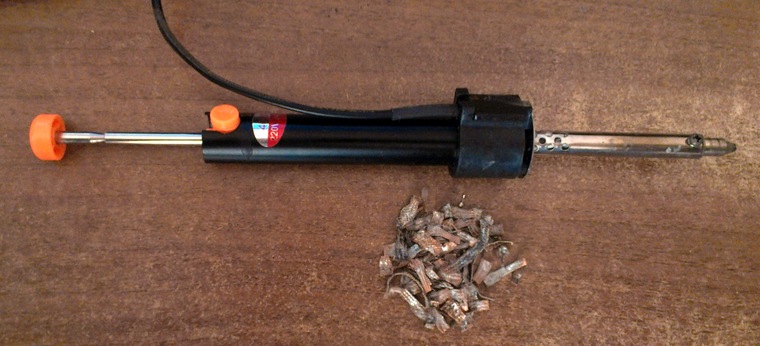
There were no further ideas. I noticed that there are no data on the outputs of two memory microcircuits, replaced them. The old textolite showed itself from the worst side - it turned black when soldering with a hairdryer (my mother told terrible tales about the textolite blackening with a hairdryer, but I didn’t believe it), the tracks fell off ... A depressing sight. Soldering without a hairdryer - helped with a soldering iron with a desoldering pump (a wonderful invention, melt the solder, press the button - and it sucks everything in, then the main thing is not to slap the board), and a copper braid (solder wick), with which a whole bunch was plagued:
After replacing the memory chips - suddenly everything stopped working. Again trash on the screen with no signs of life. Honestly, here I was ready to give up, and admit that not everything in this life can be done.
After scrutinizing the board with a magnifying glass, I managed to find 2 more faults that I did, but the memory test did not start working. Then, with a total dial-up, I discovered that there was another fault on the data bus - but I did not find it on the entire data bus. I had to cut a specific bit of the data bus into pieces to narrow the search. Finally, a short circuit was found - it turned out to be so microscopic that it was hardly visible in the magnifying glass. The reason why I got so short-circuit so easily turned out to be simple - I mistakenly replaced the usual POS60 solder with low-melting Bismuth (melting point 144 degrees).
 When in contact with a soldering iron with a temperature of 250 degrees, the flux instantly boiled, and the smallest drops of solder were scattered around. And I was puzzling why the surface turns dull after soldering ...
 The memory test worked, and it seems that the faults found during the inspection process solved the problem of switching the page, now the data bus at 0 was not reset at the most crucial moment, and switching the page works stably:
However, loading ORDOS from an external ROM was still not working. After reading 3 bytes from the rum disk with my hands through the ports (there are commands for this in Monitor-1), I saw that 2 bits of data came in incorrect (compared with the image of the ROM disk merged on the programmer). After soldering the romdisk - ORDOS booted! Joy knew no bounds:

However, the problems still remained: the memory test showed a memory error on the second page after warming up, sometimes the image on the TV disappeared, especially often when testing the second page of memory, and it was necessary to do something with the mystical K155IE5 hanging on wires:

The memory chip was easy to replace, but with the loss of the image had to torment. Suspicion fell on the permission signal for writing data from video memory to the video signal generation registers (recording there is prohibited when the processor accesses the memory). The track was long (~ 50cm), and since there is no impedance matching - the signal was reflected from the ends of the track, exceeding the allowable level 0 in TTL logic (0.4V) - this could cause problems. Therefore, I implemented sequential termination - a 220 Ohm resistor next to the signal source - the ringing disappeared, but the problem remained:
The essence of sequential termination
Let's say the wave impedance of the track is 220 ohms. Without termination, a 5V pulse will reach the end of the track, be reflected, and the instantaneous voltage there will be 10V. Most of course, cut off on the protective diodes inside the chip, but there will be a surge up to 10V. If we put a 220 Ohm resistor next to the signal source, then 2.5V will go along the track (since we get a voltage divider), when 2.5V reaches the end of the track and reflects back - just get 5V, exactly as much as you need .
The wave impedance of a track depends on its width and proximity to the ground; for thin tracks without an earthy ground below it, it is high, hundreds of ohms.
The wave impedance of a track depends on its width and proximity to the ground; for thin tracks without an earthy ground below it, it is high, hundreds of ohms.


Mystics added that when the oscilloscope ground was connected, the image disappeared. It turned out that the problem was in a bad 12V power supply unit, which apparently saved on filtering - there was a lot of debris on the ground (i.e. there was always 12V between the ground and the 12V bus, but there was a lot of noise relative to the TV or oscilloscope ground). Replacing the power supply with a better one (from FPGA demoboards) - the problem was completely resolved.
After tracking the K155IE5 on the wires, it turned out that it partially replaces the K1533IE5 soldered into the board. Why it was necessary to leave it hanging on the wires is not clear to me. K1533IE5 bit, K155IE5 soldered - and everything works! The 1533 series is the bourgeois ALS, 155 is the usual TTL. ALS has a reduced load capacity and speed, apparently this was the original reason for the replacement.
A more complete table of correspondence of domestic and foreign TTL logic
K155 - 74
K133 - 54
K530 - 54S
K531 - 74S
K533 - 74LS
K555 - 74LS
K1531 - 74F
K1533 - 74ALS
K1564 - 74HC
General view in finished form:

A small scarf on the left side -
screen shift pattern down (otherwise the first line on the LCD TVs is cut off)
The design of the board for Eagle is 3.14.by/files/orion_sync.zip Any
diodes, 1k resistor, decoupled coupler , decoupling capacitor.
Chip - 74AC1G14 / 74AC1G04 / 74HC1G14 / 74HC1G04 (1 inverter gate with / without Schmitt trigger).
3 inputs are connected to the legs 8,9,11 DD4, the output - to the foot 13 DD7.4 (respectively, the path leading to n.13 DD7 must be cut off next to DD7).
In the original circuit, which I could not find right now (somewhere on the radiocot) - OR was on the microcircuits, and the inverter was on the transistor, I did OR on the diodes and the inverter was on the microcircuit.
My first program was also found on the romdisk, which was introduced to the world, HALPER (yes, there is a small mistake in the name
 ). The tiniest thing was that I sent a hexadecimal dump written by hand to the editorial office of Radio Magazine, and even with a couple of corrections - but still, it was not too lazy for someone to type it (apparently more serious publications were not enough):
Recovery ( facepalm) However, I have not gone far in literacy since then.
Was it worth it?
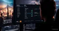
For me personally, the last screenshot was worth all the trouble. And of course, the resolution of the global problem of childhood and adolescence is priceless.In addition, it was possible to better understand how the (old) computers actually work, and to understand how sometimes I am wry-handed, because all the short circuits that I fought selflessly were made by me.
Orion 128 information
Emuverse - A Wiki with links and publications from Radio magazine .orion128.nikom.biz - A collection of all the software for Orion
zx.pk.ru/forumdisplay.php?f=56 - Forum on Orion on zx.pk.ru , they collect new Orions (and of course, many other topics on vintage computers)
www.nedopc.org/forum/viewforum.php?f=39 - Forum on Soviet computers at nedopc.org
emu80.org - a universal emulator of 8-bit computers, for Windows (Radio-86RK, "Partner", " Apogee ”,“ Mikrosha ”,“ Specialist ”,“ Orion ”,“ Micro-80 ”,“ UT-88 ”)