Creating a smart home and developing your own protocol
I must say right away that the post is focused more on ordinary people than on those who are in the subject, and is rather a report of what I did in recent days.
Here I decided to score for all the work and do something for the soul. Again he took up the soldering iron. I decided to automate everything at home. In an old apartment I had a smart house or something like that - I could turn on the light in the room via the Internet and all that.
This time I decided to take into account my mistakes. The main problem was that earlier I had one device responsible for everything, to which temperature, motion sensors, a display, buttons, etc. were connected. All this was great, but in the end the device performed only the functionality that was originally laid in it. You couldn’t just take and connect some new sensor without remodeling this device.
It was decided that it is better to make many separate devices, each of which is responsible for a strictly defined task, having the ability to easily connect them to a common network. And so that each device has an address and its own set of commands. Something like a CAN bus in modern cars. At the same time, I want the network to be decentralized, without a master device, to connect all along one wire, to be easily implemented without buying an additional controller, and so that long wires are not a problem.
On board the microcontroller there are all sorts of I²C, yes UART, but they clearly do not satisfy the conditions. In the end, it was decided to develop yourbike protocol.
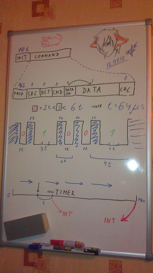
There is a dominant and recessive signal, as in CAN. In the case of wires (who knows, maybe I will also use radio or IR light), the dominant one is pressing the data line to the ground. In the normal state, the data line has a pull up to + 5V. Thus, when the device sees that the line is already pressed to the ground, it understands that some other device is already sending data, and waits for the line to be released. The data itself is encoded by the length of the dominant signals. 1T is zero, 3T is one, the pause between them is 1T. Each transmission starts with a 10T long signal initialization. After numerous experiments on the microcontroller millipede ...
... I decided that the optimal value is T = 0.000064 seconds. Moreover, there are no losses (almost?). I do not think that a large amount of data will be transmitted over this network. Display messages from Twitter on the display in the toilet if only.
The data packets themselves have the following structure: 2 bits are the priority of the packet (in case the devices send them simultaneously, which is very unlikely), 8 bits are the address of the sender, 8 bits are the address of the receiver (0xFF is the broadcast), 8 bits are the number of the command , 8 bits is the length of the data field in bytes, the corresponding number of data bytes and 8 bits is the checksum, where would it be without it.
The result is a library that implements work with this protocol completely at the interrupt level. Those. it turns out a kind of multitasking from the point of view of the rest of the program. It is enough to perform initialization once, and the microcontroller will respond to pings, even if the main program has entered an infinite loop. It does not freeze, even if the line is busy when sending the packet, the library sends it as soon as the line is released. And when a packet is received at its address, the specified function is called.
Thus, to connect a new device to the network, it’s enough for me to simply configure the library by specifying the necessary legs of the microcontroller, address and name.
We must pay tribute to one small box. I don’t have a normal oscilloscope, but a few years ago I ordered the cheapest USB oscilloscope on a ibey for a computer. Just at 1MHz. When I got it and tried it, I decided that it was a useless Chinese consumer goods, and I threw the money in vain and put it in a far box. And now I decided to get it ... If not for him, I probably still would have debugged all this. And on it, everything is immediately visible and understandable. It turned out to sit out of three wires - earth, power and data. Yes, I didn’t want to mess with the power of each device, so I decided to supply 9-12 volts of direct current everywhere, and already put a banal Krenka on each device. However, this entire network still needs to be somehow connected with a computer and the Internet. To do this, I first made a device on the COM port:

This thing worked outright shitty. And why didn’t I decide to do it right away on USB? I do not know. The FT232 chip was later purchased. Fundamentally in the QFN package. First soldered QFN case. It didn’t turn out right away, the board already turned black from overheating. But it worked! I stuck this thing in the router, because it works around the clock, and I need a connection not only with a computer, but also with the Internet.
The router is ordinary Linux. After some dances with a tambourine, I managed to suck my device to it. Next, I had to recall programming skills for nyx. The task was not so difficult - to share a virtual COM port into a network with the ability to connect several clients to it simultaneously. Then I made sure that every script received a simple script. Thus, you can easily make the router respond to various events by simply changing the shell script, without restarting the daemon. Then he did the work with fifo pseudo-file, which gave me the opportunity to send packets to the network directly from the command line. For example, the command: echo "04010803"> fifosends a packet with priority 04 to device 01 with command 08 (relay control) and data 03 (turn on the 1st and 2nd lamps). Of course, I don’t need to type all this manually, but it greatly facilitates writing scripts that automate everything. Under Windows, a library was written that connects to the daemon on the server and receives / sends packets. There is no full-fledged software yet, but I can turn on the light in the room, the TV and the receiver with the hot keys on the keyboard, which makes life very easy.
But then I decided to write my bootloader. I can no longer imagine how I could do without him. It allows you to update devices firmware directly on my network! This is a small program that sits at the end of the microcontroller's memory and runs before the main program. Her whole task is to give signs of life, and then either start the main program after a few seconds, or download and update the firmware if such a command arrives. With great difficulty, I fit all this code into one kilobyte. The count went literally bytes. Only the very basis has been implemented - no checks for line freeness, expectations and other chips. Only data transfer and checksum verification, but for the bootloader this is quite enough. How cool it is to save every byte of memory, work directly with registers,
For the computer, I wrote the appropriate command line utility that sends the device a reboot command, a command to switch to firmware mode, and the firmware itself. It is enough to register it in the Makefile of the project, and ...
By pressing one key in Programmer's Notepad I can update the firmware of any working device in my apartment. Without disconnecting, without a soldering iron, without leaving your computer. And the whole process takes 10-20 seconds. It is just mega-convenient. The configuration of some devices is much easier to change, changing the firmware itself, than to foresee everything in advance. For example, add to the wall switch a reaction to the broadcast packets that the receiver sends out, which now allows you to turn on the chandelier from the remote control of the DVD player. I remind you that a wizard is not required for this, the devices communicate directly with each other :) At the same time, you cannot kill the device with unsuccessful firmware - the bootloader always starts earlier. Now, each new device is enough to flash a simple template, making minimal changes (legs and device ID),
Now I already have six devices on my network, and so far everything works perfectly :) There were problems only with noise in the power supply, but again my oscilloscope saved me. It will be necessary to buy a full one.
upd:
GitHub project: github.com/ClusterM/clunet
Here I decided to score for all the work and do something for the soul. Again he took up the soldering iron. I decided to automate everything at home. In an old apartment I had a smart house or something like that - I could turn on the light in the room via the Internet and all that.
This time I decided to take into account my mistakes. The main problem was that earlier I had one device responsible for everything, to which temperature, motion sensors, a display, buttons, etc. were connected. All this was great, but in the end the device performed only the functionality that was originally laid in it. You couldn’t just take and connect some new sensor without remodeling this device.
It was decided that it is better to make many separate devices, each of which is responsible for a strictly defined task, having the ability to easily connect them to a common network. And so that each device has an address and its own set of commands. Something like a CAN bus in modern cars. At the same time, I want the network to be decentralized, without a master device, to connect all along one wire, to be easily implemented without buying an additional controller, and so that long wires are not a problem.
On board the microcontroller there are all sorts of I²C, yes UART, but they clearly do not satisfy the conditions. In the end, it was decided to develop your

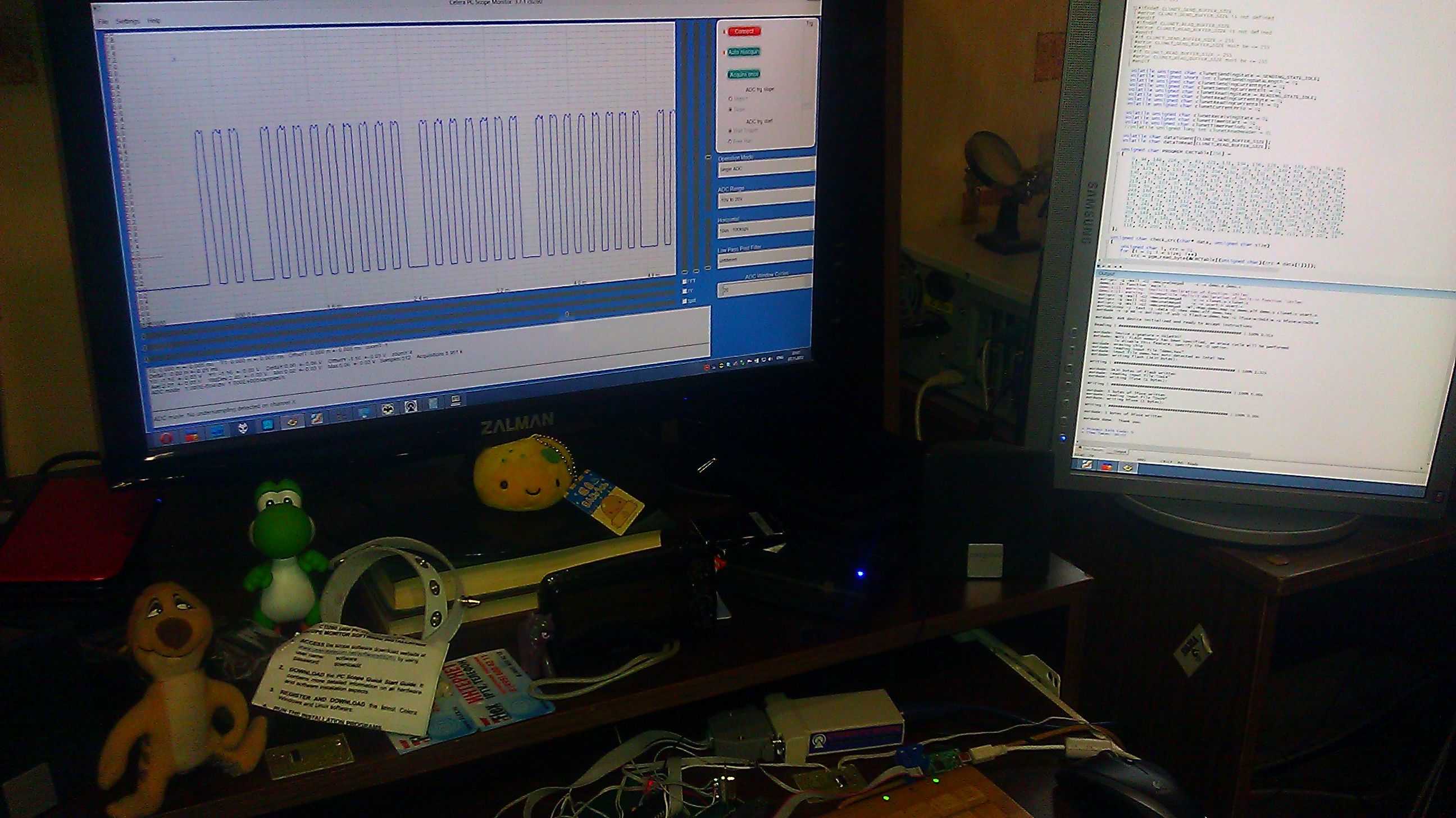
There is a dominant and recessive signal, as in CAN. In the case of wires (who knows, maybe I will also use radio or IR light), the dominant one is pressing the data line to the ground. In the normal state, the data line has a pull up to + 5V. Thus, when the device sees that the line is already pressed to the ground, it understands that some other device is already sending data, and waits for the line to be released. The data itself is encoded by the length of the dominant signals. 1T is zero, 3T is one, the pause between them is 1T. Each transmission starts with a 10T long signal initialization. After numerous experiments on the microcontroller millipede ...

... I decided that the optimal value is T = 0.000064 seconds. Moreover, there are no losses (almost?). I do not think that a large amount of data will be transmitted over this network. Display messages from Twitter on the display in the toilet if only.
The data packets themselves have the following structure: 2 bits are the priority of the packet (in case the devices send them simultaneously, which is very unlikely), 8 bits are the address of the sender, 8 bits are the address of the receiver (0xFF is the broadcast), 8 bits are the number of the command , 8 bits is the length of the data field in bytes, the corresponding number of data bytes and 8 bits is the checksum, where would it be without it.
The result is a library that implements work with this protocol completely at the interrupt level. Those. it turns out a kind of multitasking from the point of view of the rest of the program. It is enough to perform initialization once, and the microcontroller will respond to pings, even if the main program has entered an infinite loop. It does not freeze, even if the line is busy when sending the packet, the library sends it as soon as the line is released. And when a packet is received at its address, the specified function is called.
Thus, to connect a new device to the network, it’s enough for me to simply configure the library by specifying the necessary legs of the microcontroller, address and name.
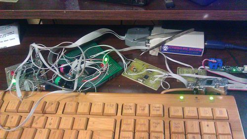
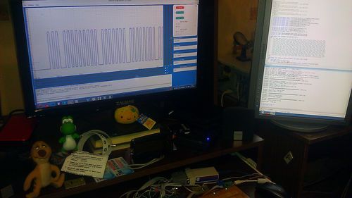
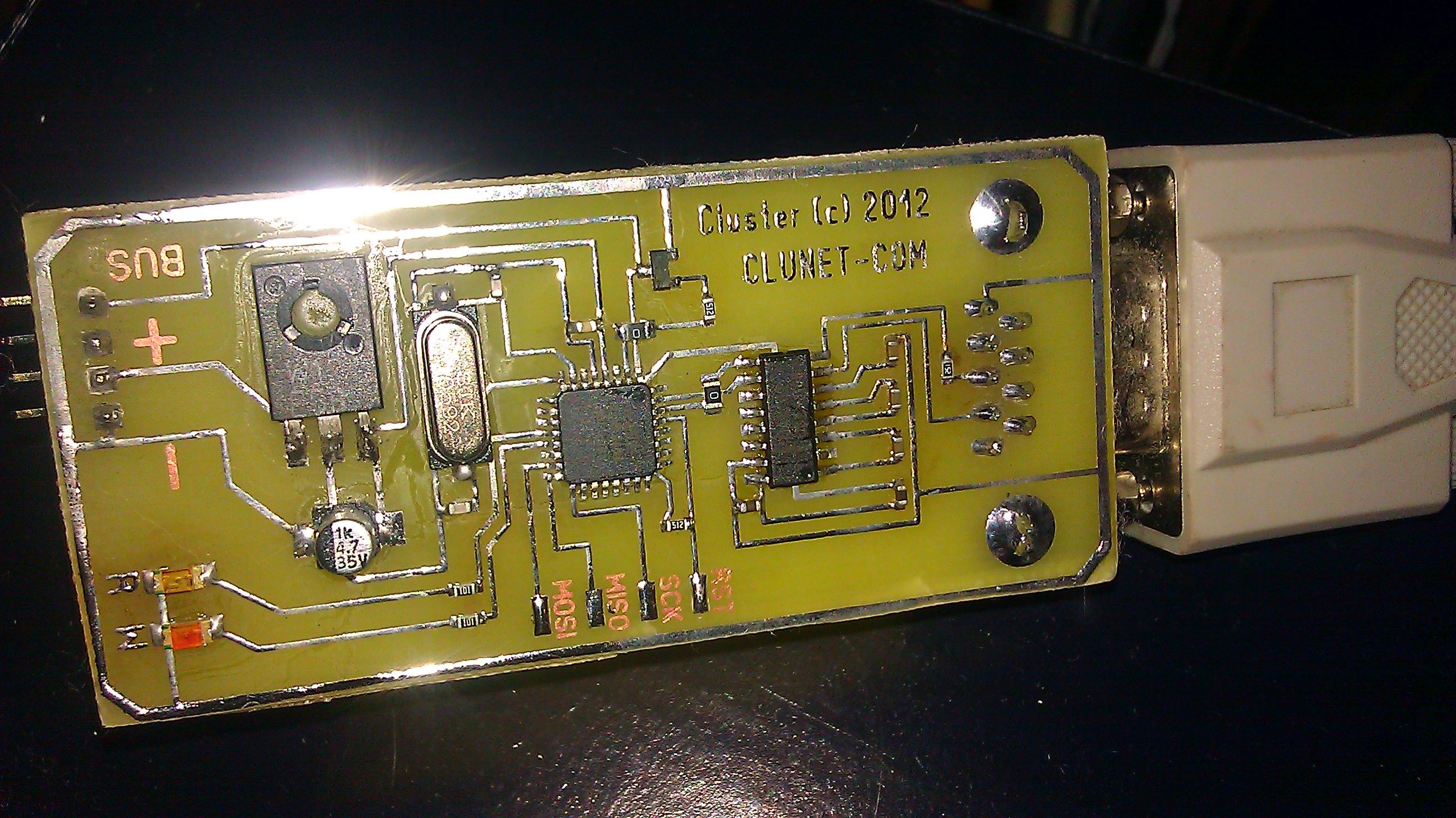
We must pay tribute to one small box. I don’t have a normal oscilloscope, but a few years ago I ordered the cheapest USB oscilloscope on a ibey for a computer. Just at 1MHz. When I got it and tried it, I decided that it was a useless Chinese consumer goods, and I threw the money in vain and put it in a far box. And now I decided to get it ... If not for him, I probably still would have debugged all this. And on it, everything is immediately visible and understandable. It turned out to sit out of three wires - earth, power and data. Yes, I didn’t want to mess with the power of each device, so I decided to supply 9-12 volts of direct current everywhere, and already put a banal Krenka on each device. However, this entire network still needs to be somehow connected with a computer and the Internet. To do this, I first made a device on the COM port:
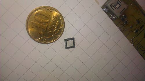
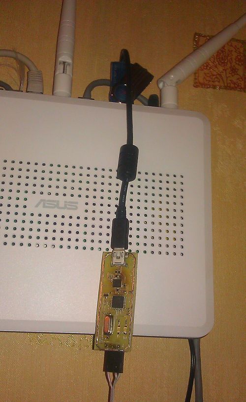
This thing worked outright shitty. And why didn’t I decide to do it right away on USB? I do not know. The FT232 chip was later purchased. Fundamentally in the QFN package. First soldered QFN case. It didn’t turn out right away, the board already turned black from overheating. But it worked! I stuck this thing in the router, because it works around the clock, and I need a connection not only with a computer, but also with the Internet.

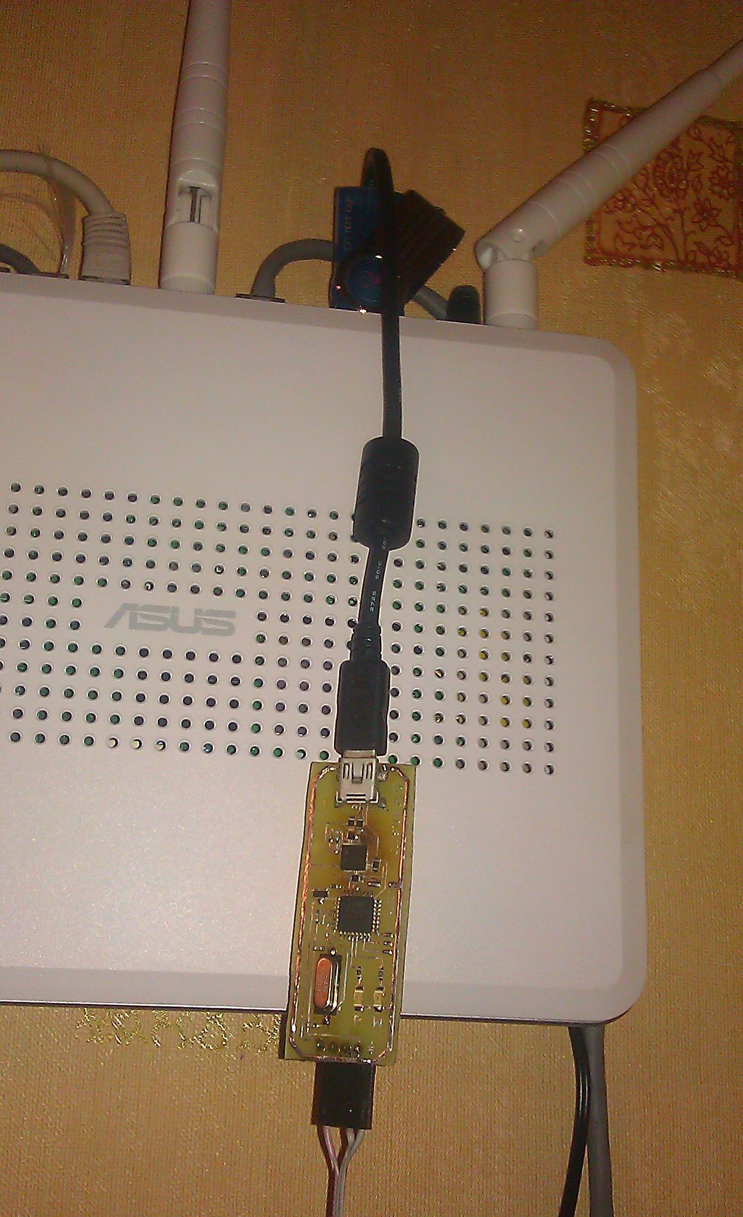
The router is ordinary Linux. After some dances with a tambourine, I managed to suck my device to it. Next, I had to recall programming skills for nyx. The task was not so difficult - to share a virtual COM port into a network with the ability to connect several clients to it simultaneously. Then I made sure that every script received a simple script. Thus, you can easily make the router respond to various events by simply changing the shell script, without restarting the daemon. Then he did the work with fifo pseudo-file, which gave me the opportunity to send packets to the network directly from the command line. For example, the command: echo "04010803"> fifosends a packet with priority 04 to device 01 with command 08 (relay control) and data 03 (turn on the 1st and 2nd lamps). Of course, I don’t need to type all this manually, but it greatly facilitates writing scripts that automate everything. Under Windows, a library was written that connects to the daemon on the server and receives / sends packets. There is no full-fledged software yet, but I can turn on the light in the room, the TV and the receiver with the hot keys on the keyboard, which makes life very easy.
But then I decided to write my bootloader. I can no longer imagine how I could do without him. It allows you to update devices firmware directly on my network! This is a small program that sits at the end of the microcontroller's memory and runs before the main program. Her whole task is to give signs of life, and then either start the main program after a few seconds, or download and update the firmware if such a command arrives. With great difficulty, I fit all this code into one kilobyte. The count went literally bytes. Only the very basis has been implemented - no checks for line freeness, expectations and other chips. Only data transfer and checksum verification, but for the bootloader this is quite enough. How cool it is to save every byte of memory, work directly with registers,
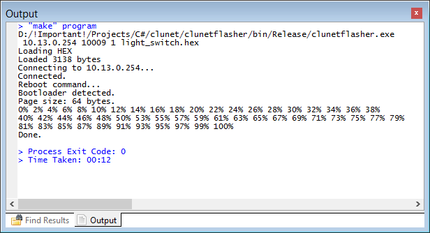
For the computer, I wrote the appropriate command line utility that sends the device a reboot command, a command to switch to firmware mode, and the firmware itself. It is enough to register it in the Makefile of the project, and ...
By pressing one key in Programmer's Notepad I can update the firmware of any working device in my apartment. Without disconnecting, without a soldering iron, without leaving your computer. And the whole process takes 10-20 seconds. It is just mega-convenient. The configuration of some devices is much easier to change, changing the firmware itself, than to foresee everything in advance. For example, add to the wall switch a reaction to the broadcast packets that the receiver sends out, which now allows you to turn on the chandelier from the remote control of the DVD player. I remind you that a wizard is not required for this, the devices communicate directly with each other :) At the same time, you cannot kill the device with unsuccessful firmware - the bootloader always starts earlier. Now, each new device is enough to flash a simple template, making minimal changes (legs and device ID),
Now I already have six devices on my network, and so far everything works perfectly :) There were problems only with noise in the power supply, but again my oscilloscope saved me. It will be necessary to buy a full one.
upd:
GitHub project: github.com/ClusterM/clunet