VGA adapter for Altera Cyclone III FPGA
- Tutorial
 Hi Habr - in this article I am going to share my successes in the development of Altera Cyclone III FPGAs . After blinking lights and games with counters - I decided to do something more serious. I made the simplest VGA adapter. Its main parts will be discussed. The article is more focused on beginners, as for experienced ones this task will not be difficult, but in my opinion, for mastering it is a good training task. I conduct my experiments on the Altera DE0 debug board . I will describe the circuit on Verilog , Wednesday - Quartus II v 12.0. So - welcome to kat:
 The block diagram of the VGA adapter
Let's start by figuring out what VGA consists of and what it is eaten with
Initially, VGA was created for monitors with a cathode ray tube, so we are managing here not a matrix of pixels, as in LCD displays, but an electron beam that runs around the screen and we must amplify / weaken it or turn it off altogether at the right moments. When I started working with VGA - I was surprised - how little detailed information describing this standard I could find - which, incidentally, is understandable - it is already outdated and manufacturers are abandoning it. I hope my article will help someone in mastering the standard.
An excerpt from a Wiki article about VGA:
VGA (as well as EGA) consists of the following main subsystems (popularly the word “sequencer” was a set of registers for controlling access to video memory planes):
- The graphics controller (Graphics Controller), through which data is exchanged between the central processor and video memory. It has the ability to perform bitwise operations on the transmitted data.
- Video memory (Display Memory), which contains the data displayed on the monitor screen. 256 kB DRAM is divided into four 64 kB color layers.
- Serial Converter (Serializer or Sequencer) - converts data from video memory into a bit stream transmitted to the attribute controller.
- Controller attribute (Attribute Controller) - via palette converts the input data into color values.
- Synchronizer (Sequencer) - controls the temporal parameters of the video adapter and switching color layers.
- A CRT controller (CRT Controller) - generates synchronization signals for the CRT.
In the role of synchronizer, we will have a 50 MHz generator present on the debug board.
We will not implement video memory and data exchange with the processor yet - instead, we ourselves will generate a bit stream for the attribute controller.
So - the task is divided into the implementation of the following blocks:
- Synchronizer - the frequency of 50 megahertz is not very convenient for us, so it will have to be slightly changed
- A CRT controller that will issue synchronization signals in accordance with the requirements of the VGA standard
- Picture generator - we will use it for debugging - the block will draw a simple picture and give it to the CRT controller
Synchronizer
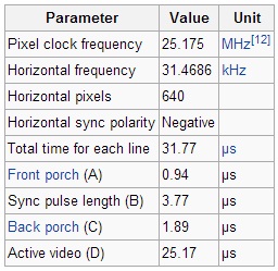
To begin with, we climb onto the English Wiki and watch Signal timings for VGA, from where we find out that the clock frequency should be 25.175 MHz.
Here we have the first task - to make from 50 MHz - 25.175 MHz. PLL or PLL will help us in this matter .
Using the Mega Wizard, we create our PLL with the necessary settings. To do this, go to Tools / MegaWizard Plug-InManager. There we select the type of the output file Verilog HDL I / O ALTPLL and configure it - set the input frequency and then convert it. We need to get the frequency of 25.175 MHz, while we can only multiply and divide by an integer, that is, we need to translate the number 0.5035 into a fraction. You can multiply by 5035 and divide by 10000, but note that you can reduce both numbers by 5. We get the fraction 1007 / 2000. In this case, the wizard will itself bring the required factor closer to the fraction available to it. We include the resulting module in the project, connect our shred from the board to its input, and for the output we create wire, which we then start somewhere, the main goal of this item is achieved - to obtain a frequency of 25.175 MHz.
CRT controller
Clock Generators
We move on. Now we need to create modules that issue clock signals that satisfy the horizontal and vertical synchronization timings, that is, this for horizontal synchronization:
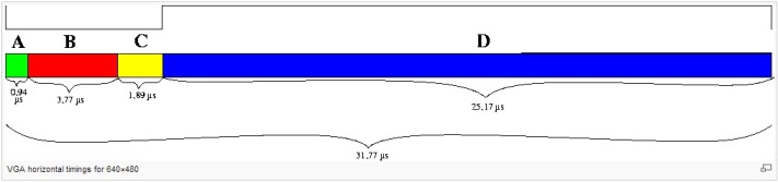
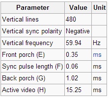
That is, we must hold the synchronization line in high state for time A before outputting data, then press it to ground for time B, then put it in a high state, wait for time C, and only then there is a data stream - the ray starts to run through the line in time D and during this time we have to manage to set all the pixels with a frequency of 25.175 megahertz and so for each strings. Vertical synchronization works almost the same way, only instead of pixels we transmit lines and in one period of the clock pulse we draw the entire frame.
The task was decided - to create a block that implements the sequence described above, taking the VGA_CLK frequency as an input, from the inputs we add, perhaps, a reset signal. The implementation of such a block is not simple, but very simple:
With a period of 1 / VGA_CLK = 0.03972194637537239324726911618669 microseconds, we need 24 cycles on A, 95 on B, 48 on C, and 640 on D. The same thing for vertical synchronization, but here it’s more convenient to clock out at 25.175 megahertz, and on the rising edges of the horizontal synchronization signal, then all the delays can be considered in the periods of the line drawing. In addition, we have an “idle” area on the screen, it’s real - the screen is a bit larger in ticks, and we should draw only in the visible area, so it’s also advisable that the module tells us the current coordinates of the ray, and even if we are going to assign each pixel some color - you can’t do without knowing the current position of the beam.
Synchronization module
module VGA_SYNC(
						input CLK,
						input SYNC_RST_N,
						output reg H_SYNC_CLK,
						output reg V_SYNC_CLK,
						output wire [10:0]oCurrent_X,
						output wire [10:0]oCurrent_Y,
						output reg oSYNC_COLOR);
parameter A_TIME_H = 24;
parameter B_TIME_H = 95;
parameter C_TIME_H = 48;
parameter D_TIME_H = 640;
parameter TOTAL_TIME_H = A_TIME_H + B_TIME_H + C_TIME_H + D_TIME_H;
parameter BLANK_H = A_TIME_H + B_TIME_H + C_TIME_H;
parameter A_TIME_V = 10;
parameter B_TIME_V = 2;
parameter C_TIME_V = 33;
parameter D_TIME_V = 480;
parameter TOTAL_TIME_V = A_TIME_V + B_TIME_V + C_TIME_V + D_TIME_V;
parameter BLANK_V = A_TIME_V + B_TIME_V + C_TIME_V;
reg 			[10:0]H_Counter;
reg 			[10:0]V_Counter;
assign	oCurrent_X	=	(H_Counter >= BLANK_H)	?	H_Counter-BLANK_H	:	11'h0	;
assign	oCurrent_Y	=	(V_Counter >= BLANK_V)	?	V_Counter-BLANK_V	:	11'h0	;
always@(posedge(CLK) or negedge(SYNC_RST_N))
begin
	if(!SYNC_RST_N)
	begin
		H_Counter	<=	1'b0;
		H_SYNC_CLK	<=	1'b1;
	end
	else
	begin
		if(H_Counter < (TOTAL_TIME_H-1))
		H_Counter	<=	H_Counter + 1'b1;
		else
			begin
			H_Counter	<=	1'b0;
			oSYNC_COLOR <= 1'b0;
			end
		if(H_Counter == A_TIME_H-1)
		H_SYNC_CLK	<=	1'b0;
		if(H_Counter == A_TIME_H + B_TIME_H-1)
		H_SYNC_CLK	<=	1'b1;
		if(H_Counter == BLANK_H)
		oSYNC_COLOR <= 1'b1;
	end
end
always@(posedge(H_SYNC_CLK) or negedge(SYNC_RST_N))
begin
	if(!SYNC_RST_N)
	begin
		V_Counter	<=	1'b0;
		V_SYNC_CLK	<=	1'b1;
	end
	else
	begin
		if(V_Counter < (TOTAL_TIME_V-1))
		V_Counter	<=	V_Counter + 1'b1;
		else
		V_Counter	<=	1'b0;
		if(V_Counter == A_TIME_V-1)
		V_SYNC_CLK	<=	1'b0;
		if(V_Counter == A_TIME_V + B_TIME_V-1)
		V_SYNC_CLK	<=	1'b1;
	end
end
endmodule
Output module
In fact, the pulses are generated, the coordinates of the point are known, it remains only to turn on the desired color in time, while the ray runs through the line - for this we create a module that receives synchronization signals, frequency 25.175 MHz, 3 color buses and coordinates, and the output is 4-bit R-2R DAC for each color, and further - VGA connector
Output Module
module VGA_OUT(RESET,
					SYNC_COLOR,
					VGA_CLK,
					oVGA_R,
					oVGA_G,
					oVGA_B,
					iVGA_R,
					iVGA_G,
					iVGA_B,
					Current_X,
					Current_Y);
input wire VGA_CLK;
input wire RESET;
input wire SYNC_COLOR;
input wire [10:0]Current_X;
input wire [10:0]Current_Y;
input wire [3:0]iVGA_R;
input wire [3:0]iVGA_G;
input wire [3:0]iVGA_B;
output reg [3:0]oVGA_R;
output reg [3:0]oVGA_G;
output reg [3:0]oVGA_B;
always@(posedge VGA_CLK or negedge RESET)
begin
	if(!RESET)
	begin
		oVGA_R	<=	0;
		oVGA_G	<=	0;
		oVGA_B	<=	0;
	end
	else
	begin
				oVGA_R	<=	((SYNC_COLOR == 1)&&(Current_X > 0)&&(Current_Y > 0)) ? iVGA_R : 0;
				oVGA_G	<=	((SYNC_COLOR == 1)&&(Current_X > 0)&&(Current_Y > 0)) ? iVGA_G : 0;
				oVGA_B	<=	((SYNC_COLOR == 1)&&(Current_X > 0)&&(Current_Y > 0)) ? iVGA_B : 0;
	end
end
endmodule
To check the system - we will generate some kind of picture - this block is not described by me, I took it from the exterovs of Alter’s, well, in general, there’s nothing to deal with - we only need a picture from this module
Bistrim Generation Module
module	VGA_BITSTREAM	(	//	Read Out Side
						oRed,
						oGreen,
						oBlue,
						iVGA_X,
						iVGA_Y,
						iVGA_CLK,
						//	Control Signals
						iRST_n,
						iColor_SW	);
//	Read Out Side
output	reg	[9:0]	oRed;
output	reg	[9:0]	oGreen;
output	reg	[9:0]	oBlue;
input	[9:0]		iVGA_X;
input	[9:0]		iVGA_Y;
input				iVGA_CLK;
//	Control Signals
input				iRST_n;
input				iColor_SW;
always@(posedge iVGA_CLK or negedge iRST_n)
begin
	if(!iRST_n)
	begin
		oRed	<=	0;
		oGreen	<=	0;
		oBlue	<=	0;
	end
	else
	begin
		if(iColor_SW == 1)
		begin
			if (iVGA_Y<120)
			begin
				oRed	<=	(iVGA_X<40)						?			0	:
							(iVGA_X>=40 && iVGA_X<80)		?			1	:
							(iVGA_X>=80 && iVGA_X<120)		?			2	:
							(iVGA_X>=120 && iVGA_X<160)		?			3	:
							(iVGA_X>=160 && iVGA_X<200)		?			4	:
							(iVGA_X>=200 && iVGA_X<240)		?			5	:
							(iVGA_X>=240 && iVGA_X<280)		?			6	:
							(iVGA_X>=280 && iVGA_X<320)		?			7	:
							(iVGA_X>=320 && iVGA_X<360)		?			8	:
							(iVGA_X>=360 && iVGA_X<400)		?			9	:
							(iVGA_X>=400 && iVGA_X<440)		?			10	:
							(iVGA_X>=440 && iVGA_X<480 )	?			11	:
							(iVGA_X>=480 && iVGA_X<520 )	?			12	:
							(iVGA_X>=520 && iVGA_X<560 )	?			13	:
							(iVGA_X>=560 && iVGA_X<600 )	?			14	:
																		15	;
				oGreen	<=	0;
				oBlue	<=	0;
			end
			else if (iVGA_Y>=120 && iVGA_Y<240)
			begin
				oRed	<=	0;
				oGreen	<=	(iVGA_X<40)						?			15	:
							(iVGA_X>=40 && iVGA_X<80)		?			14	:
							(iVGA_X>=80 && iVGA_X<120)		?			13	:
							(iVGA_X>=120 && iVGA_X<160)		?			12	:
							(iVGA_X>=160 && iVGA_X<200)		?			11	:
							(iVGA_X>=200 && iVGA_X<240)		?			10	:
							(iVGA_X>=240 && iVGA_X<280)		?			9	:
							(iVGA_X>=280 && iVGA_X<320)		?			8	:
							(iVGA_X>=320 && iVGA_X<360)		?			7	:
							(iVGA_X>=360 && iVGA_X<400)		?			6	:
							(iVGA_X>=400 && iVGA_X<440)		?			5	:
							(iVGA_X>=440 && iVGA_X<480 )	?			4	:
							(iVGA_X>=480 && iVGA_X<520 )	?			3	:
							(iVGA_X>=520 && iVGA_X<560 )	?			2	:
							(iVGA_X>=560 && iVGA_X<600 )	?			1	:
																		0	;
				oBlue	<=	0;
			end
			else if (iVGA_Y>=240 && iVGA_Y<360)
			begin
				oRed	<=	0;
				oGreen	<=	0;
				oBlue	<=	(iVGA_X<40)						?			0	:
							(iVGA_X>=40 && iVGA_X<80)		?			1	:
							(iVGA_X>=80 && iVGA_X<120)		?			2	:
							(iVGA_X>=120 && iVGA_X<160)		?			3	:
							(iVGA_X>=160 && iVGA_X<200)		?			4	:
							(iVGA_X>=200 && iVGA_X<240)		?			5	:
							(iVGA_X>=240 && iVGA_X<280)		?			6	:
							(iVGA_X>=280 && iVGA_X<320)		?			7	:
							(iVGA_X>=320 && iVGA_X<360)		?			8	:
							(iVGA_X>=360 && iVGA_X<400)		?			9	:
							(iVGA_X>=400 && iVGA_X<440)		?			10	:
							(iVGA_X>=440 && iVGA_X<480 )	?			11	:
							(iVGA_X>=480 && iVGA_X<520 )	?			12	:
							(iVGA_X>=520 && iVGA_X<560 )	?			13	:
							(iVGA_X>=560 && iVGA_X<600 )	?			14	:
																		15	;
			end
			else
			begin
				oRed	<=	(iVGA_X<40)						?			15	:
							(iVGA_X>=40 && iVGA_X<80)		?			14	:
							(iVGA_X>=80 && iVGA_X<120)		?			13	:
							(iVGA_X>=120 && iVGA_X<160)		?			12	:
							(iVGA_X>=160 && iVGA_X<200)		?			11	:
							(iVGA_X>=200 && iVGA_X<240)		?			10	:
							(iVGA_X>=240 && iVGA_X<280)		?			9	:
							(iVGA_X>=280 && iVGA_X<320)		?			8	:
							(iVGA_X>=320 && iVGA_X<360)		?			7	:
							(iVGA_X>=360 && iVGA_X<400)		?			6	:
							(iVGA_X>=400 && iVGA_X<440)		?			5	:
							(iVGA_X>=440 && iVGA_X<480 )	?			4	:
							(iVGA_X>=480 && iVGA_X<520 )	?			3	:
							(iVGA_X>=520 && iVGA_X<560 )	?			2	:
							(iVGA_X>=560 && iVGA_X<600 )	?			1	:
																		0	;
				oGreen	<=	(iVGA_X<40)						?			15	:
							(iVGA_X>=40 && iVGA_X<80)		?			14	:
							(iVGA_X>=80 && iVGA_X<120)		?			13	:
							(iVGA_X>=120 && iVGA_X<160)		?			12	:
							(iVGA_X>=160 && iVGA_X<200)		?			11	:
							(iVGA_X>=200 && iVGA_X<240)		?			10	:
							(iVGA_X>=240 && iVGA_X<280)		?			9	:
							(iVGA_X>=280 && iVGA_X<320)		?			8	:
							(iVGA_X>=320 && iVGA_X<360)		?			7	:
							(iVGA_X>=360 && iVGA_X<400)		?			6	:
							(iVGA_X>=400 && iVGA_X<440)		?			5	:
							(iVGA_X>=440 && iVGA_X<480 )	?			4	:
							(iVGA_X>=480 && iVGA_X<520 )	?			3	:
							(iVGA_X>=520 && iVGA_X<560 )	?			2	:
							(iVGA_X>=560 && iVGA_X<600 )	?			1	:
																		0	;
				oBlue	<=	(iVGA_X<40)						?			15	:
							(iVGA_X>=40 && iVGA_X<80)		?			14	:
							(iVGA_X>=80 && iVGA_X<120)		?			13	:
							(iVGA_X>=120 && iVGA_X<160)		?			12	:
							(iVGA_X>=160 && iVGA_X<200)		?			11	:
							(iVGA_X>=200 && iVGA_X<240)		?			10	:
							(iVGA_X>=240 && iVGA_X<280)		?			9	:
							(iVGA_X>=280 && iVGA_X<320)		?			8	:
							(iVGA_X>=320 && iVGA_X<360)		?			7	:
							(iVGA_X>=360 && iVGA_X<400)		?			6	:
							(iVGA_X>=400 && iVGA_X<440)		?			5	:
							(iVGA_X>=440 && iVGA_X<480 )	?			4	:
							(iVGA_X>=480 && iVGA_X<520 )	?			3	:
							(iVGA_X>=520 && iVGA_X<560 )	?			2	:
							(iVGA_X>=560 && iVGA_X<600 )	?			1	:
																		0	;
			end
		end
		else
		begin
			oRed	<=	(iVGA_Y<120)					?			3	:
						(iVGA_Y>=120 && iVGA_Y<240)		?			7	:
						(iVGA_Y>=240 && iVGA_Y<360)		?			11	:
																	15	;
			oGreen	<=	(iVGA_X<80)						?			1	:
						(iVGA_X>=80 && iVGA_X<160)		?			3	:
						(iVGA_X>=160 && iVGA_X<240)		?			5	:
						(iVGA_X>=240 && iVGA_X<320)		?			7	:
						(iVGA_X>=320 && iVGA_X<400)		?			9	:
						(iVGA_X>=400 && iVGA_X<480)		?			11	:
						(iVGA_X>=480 && iVGA_X<560)		?			13	:
																	15	;
			oBlue	<=	(iVGA_Y<60)						?			15	:
						(iVGA_Y>=60 && iVGA_Y<120)		?			13	:
						(iVGA_Y>=120 && iVGA_Y<180)		?			11	:
						(iVGA_Y>=180 && iVGA_Y<240)		?			9	:
						(iVGA_Y>=240 && iVGA_Y<300)		?			7	:
						(iVGA_Y>=300 && iVGA_Y<360)		?			5	:
						(iVGA_Y>=360 && iVGA_Y<420)		?			3	:
																	1	;
		end
	end
end
endmodule
Main module
module VGA_MAIN(CLOCK_50,
KEY,
LEDG,
VGA_HS,
VGA_VS,
VGA_R,
VGA_G,
VGA_B,
SW
);
input CLOCK_50;
input [2:0]KEY;
input [9:0]SW;
output [9:0]LEDG;
output VGA_HS; // VGA H_SYNC
output VGA_VS; // VGA V_SYNC
output [3:0] VGA_R; // VGA Red[3:0]
output [3:0] VGA_G; // VGA Green[3:0]
output [3:0] VGA_B; // VGA Blue[3:0]
wire VGA_CLK;
wire H_SYNC_CLK;
wire V_SYNC_CLK;
wire RESET;
wire [10:0]Current_X;
wire [10:0]Current_Y;
wire SYNC_COLOR;
reg [3:0] iVGA_R;
reg [3:0] iVGA_G;
reg [3:0] iVGA_B;
wire [3:0] irVGA_R;
wire [3:0] irVGA_G;
wire [3:0] irVGA_B;
assign irVGA_R[3:0] = iVGA_R[3:0];
assign irVGA_G[3:0] = iVGA_G[3:0];
assign irVGA_B[3:0] = iVGA_B[3:0];
assign RESET = KEY[0];
assign VGA_HS = H_SYNC_CLK;
assign VGA_VS = V_SYNC_CLK;
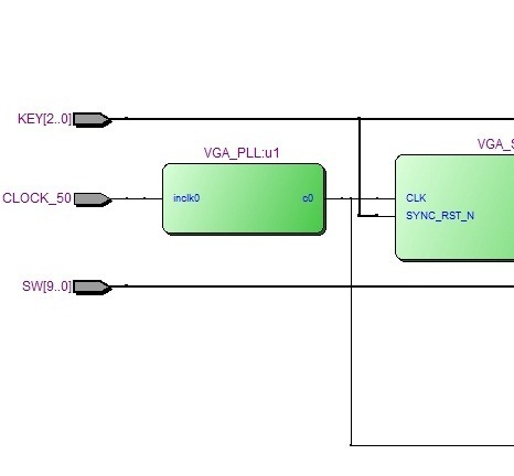
VGA_PLL u1
( .inclk0(CLOCK_50),
.c0(VGA_CLK)
);
VGA_SYNC u2
( .CLK(VGA_CLK),
.H_SYNC_CLK(H_SYNC_CLK),
.V_SYNC_CLK(V_SYNC_CLK),
.SYNC_RST_N(KEY[0]),
.oCurrent_X(Current_X),
.oCurrent_Y(Current_Y),
.oSYNC_COLOR(SYNC_COLOR));
VGA_OUT u3
(
.oVGA_R(VGA_R[3:0]),
.oVGA_G(VGA_G[3:0]),
.oVGA_B(VGA_B[3:0]),
.iVGA_R(iVGA_R[3:0]),
.iVGA_G(iVGA_G[3:0]),
.iVGA_B(iVGA_B[3:0]),
.VGA_CLK(VGA_CLK),
.Current_X(Current_X),
.Current_Y(Current_Y),
.SYNC_COLOR(SYNC_COLOR),
.RESET(RESET)
);
VGA_BITSTREAM u4(.oRed(irVGA_R),
.oGreen(irVGA_G),
.oBlue(irVGA_B),
.iVGA_X(Current_X),
.iVGA_Y(Current_Y),
.iVGA_CLK(VGA_CLK),
.iRST_n(RESET),
.iColor_SW(SW[0]));
endmodule
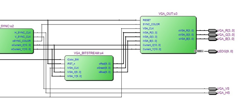
It turned out here is such a structural diagram:
Well, the video works:
In general - the first step with creating your own video card has been made - it remains to attach video memory and connect it all with an external controller - for example, STM32. In the future, I want to make the controller generate a video stream and send it to the video adapter, which displays it on the screen. Of course, it’s certainly not worth talking about the practical meaning of all this - things are already outdated and rather primitive, everything was done only for the purpose of training and consolidating skills, somewhere I certainly ran into it here, so if you have any questions, tips and comments, write in the comments