STM32 weather station, analogue indication
Having studied the comments on the article, I immediately set to work. There was a goal:
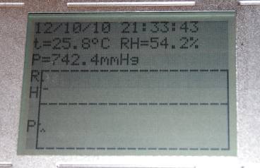
As a result: the interface was finalized, debugging information removed from the start screen; the LCD module (LCD) has been improved - pressure and humidity graphs have appeared; added external RTC (RTC) with ionistor. Well and most importantly, a direction indicator is added.
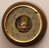
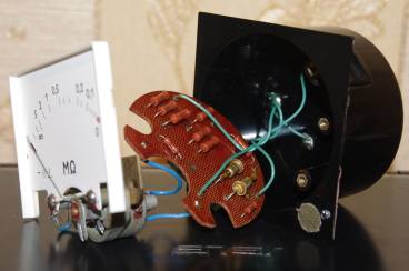
The easiest way to get an arrow indication is to apply voltage to the meter head. The desired voltage will form the digital-to-analog converter of the microcontroller. The STM32L has a dual-channel multi-function DAC . At the flea market, the first device in good condition was purchased: in the
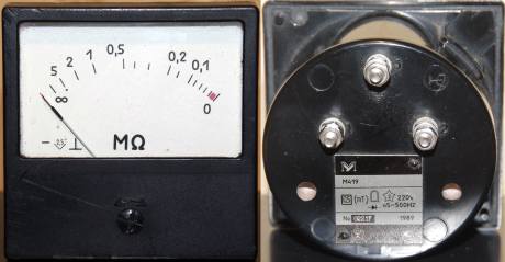
first place, a board with parts was thrown out of the device.
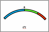
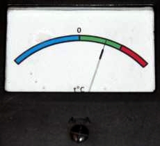
We draw a scale:
Initialization of a digital-to-analog coder and ports:
value record:
The output signal is enough to control the arrow, the voltage does not sag, the microcontroller does not heat up. A value of 160 displays the arrow in the middle of the scale. As a result, we have the following picture at +25:
The graphic mode was not easy, I didn’t want to give the microcontroller’s memory to store the displayed information, but for this it was necessary to implement reading from the LCD. It was not possible to configure the port for input and output at the same time, so you have to tell it to read or write before each write or read.
Port Configurations: Output -
to receive data -
There was also a pitfall “dumy read” - after setting the address, the first reading gives garbage, the second data.
After that the function PutPixel, DrawLine, Rectangle (remembered childhood).
The ChRV chip was chosen DS2417 with one-wire interface, it famously coexisted on the same bus as the DS18B20.
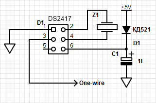
The device is selected using the same commands 55h + id, but reading from DS2417 66h and DS18B20 BEh. The ionistor included in the power supply circuit ensures the operation of the watch even with the power supply turned off.
Sources of the project .
As a result: the interface was finalized, debugging information removed from the start screen; the LCD module (LCD) has been improved - pressure and humidity graphs have appeared; added external RTC (RTC) with ionistor. Well and most importantly, a direction indicator is added.
Pointer and DAC
The easiest way to get an arrow indication is to apply voltage to the meter head. The desired voltage will form the digital-to-analog converter of the microcontroller. The STM32L has a dual-channel multi-function DAC . At the flea market, the first device in good condition was purchased: in the
first place, a board with parts was thrown out of the device.
We draw a scale:
Initialization of a digital-to-analog coder and ports:
  GPIO_InitStructure.GPIO_Pin =  GPIO_Pin_4;
  GPIO_InitStructure.GPIO_Mode = GPIO_Mode_AN;
  GPIO_InitStructure.GPIO_PuPd = GPIO_PuPd_NOPULL;
  GPIO_Init(GPIOA, &GPIO_InitStructure);
  //Тактирование DAC:
  RCC_APB1PeriphClockCmd(RCC_APB1Periph_DAC, ENABLE);
  //Инициализация DAC:
  DAC_InitTypeDef DAC_InitStructure;
  /* DAC channel1 Configuration */
  DAC_InitStructure.DAC_Trigger = DAC_Trigger_None;
  DAC_InitStructure.DAC_WaveGeneration = DAC_WaveGeneration_None;
  DAC_InitStructure.DAC_OutputBuffer = DAC_OutputBuffer_Enable;
  /* DAC Channel1 Init */
  DAC_Init(DAC_Channel_1, &DAC_InitStructure);
  /* Enable DAC Channel1 */
  DAC_Cmd(DAC_Channel_1, ENABLE);
value record:
DAC_SetChannel1Data(DAC_Align_12b_R, 160 + temperature * 3);The output signal is enough to control the arrow, the voltage does not sag, the microcontroller does not heat up. A value of 160 displays the arrow in the middle of the scale. As a result, we have the following picture at +25:
Charts and LCDs
The graphic mode was not easy, I didn’t want to give the microcontroller’s memory to store the displayed information, but for this it was necessary to implement reading from the LCD. It was not possible to configure the port for input and output at the same time, so you have to tell it to read or write before each write or read.
Port Configurations: Output -
  GPIO_InitStructure.GPIO_Pin = DATA_PIN0 | DATA_PIN1 | DATA_PIN2 | DATA_PIN3 | DATA_PIN4 | DATA_PIN5 | DATA_PIN6 | DATA_PIN7;
  GPIO_InitStructure.GPIO_Mode = GPIO_Mode_OUT;
  GPIO_InitStructure.GPIO_OType = GPIO_OType_OD;
  GPIO_InitStructure.GPIO_PuPd = GPIO_PuPd_UP;
  GPIO_InitStructure.GPIO_Speed = GPIO_Speed_2MHz;
  GPIO_Init( DATA_PORT, &GPIO_InitStructure);
to receive data -
  GPIO_InitStructure.GPIO_Pin = DATA_PIN0 | DATA_PIN1 | DATA_PIN2 | DATA_PIN3 | DATA_PIN4 | DATA_PIN5 | DATA_PIN6 | DATA_PIN7;
  GPIO_InitStructure.GPIO_Mode = GPIO_Mode_IN;
  GPIO_InitStructure.GPIO_Speed = GPIO_Speed_10MHz;
  GPIO_Init( DATA_PORT, &GPIO_InitStructure);
There was also a pitfall “dumy read” - after setting the address, the first reading gives garbage, the second data.
After that the function PutPixel, DrawLine, Rectangle (remembered childhood).
PRV
The ChRV chip was chosen DS2417 with one-wire interface, it famously coexisted on the same bus as the DS18B20.
The device is selected using the same commands 55h + id, but reading from DS2417 66h and DS18B20 BEh. The ionistor included in the power supply circuit ensures the operation of the watch even with the power supply turned off.
Sources of the project .