Breadboard - an electronic designer for everyone
Hello, Habr!
Not so long ago, an article about Arduino thundered here , spawning a holivar in the comments. Many Arduino supporters, they said, just want to collect something like flashing LEDs in order to diversify their leisure time and play. However, they do not want to bother with etching boards and soldering. As one of the alternatives, comrade dedsky mentioned the Znatok designer, but his capabilities are limited by the set of parts included in the kit, and the designer is still childish. I want to offer another alternative - the so-called Breadboard, a breadboard for mounting without soldering.
Caution, a lot of pictures.
The main purpose of this board is to design and debug prototypes of various devices. This device consists of holes-nests with a pitch of 2.54 mm (0.1 inches), it is with this (or a multiple of it) pitch that the conclusions are located on most modern radio components (SMD does not count). Development boards come in various sizes, but in most cases they consist of these identical blocks:
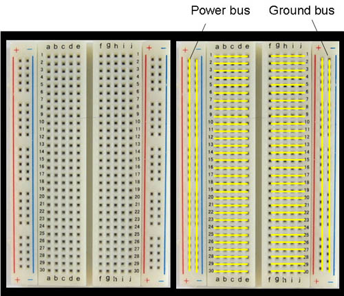
The electrical connection diagram of the sockets is shown in the right figure: five holes on each side, in each of the rows (in this case 30) are electrically connected to each other. On the left and on the right there are two power lines: here all the holes in the column are interconnected. The slot in the middle is designed for installation and convenient removal of microcircuits in DIP packages. To assemble the circuit, radio components and jumpers are inserted into the holes, since I got the board without factory jumpers - I made them from metal paper clips, and small ones (to connect adjacent sockets) from staples for staplers.
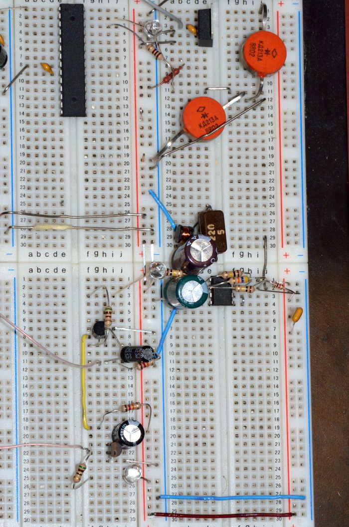
It may seem that the larger the board - the greater its functionality, this is not entirely true. A very small chance that someone (especially from beginners) will assemble a device that will occupy all segments of the board, here are several devices at the same time - yes. For example, here I collected electronic ignition on a microcontroller, a multivibrator on transistors and a frequency generator for an LC meter:
To justify the title of the article, I will cite several devices. A description of what and where to insert will be on the images.

In order to assemble one of the circuits described below, you will need a breadboard type board and a set of jumpers. In addition, it is desirable to have a suitable power source, in the simplest case, the battery (s), for the convenience of its connection (s) it is recommended to use a special container. You can use the power supply, but in this case you need to be careful and try not to burn anything, since the PSU is much more expensive than the batteries. Other details will be given in the description of the circuit itself.
One of the simplest designs. On the circuit diagrams it is depicted as follows:
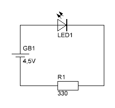
Of the details you will need: a low-power LED, any resistor at 300Ω-1kΩ and a power supply at 4.5-5V. In my case, a powerful Soviet resistor (the first that came to hand) at 430 Ohms (as indicated by the inscription K43 on the resistor itself), and as a power source - 3 finger-type (AA type) batteries in a container: a total of 1.5V * 3 = 4, 5B.
On the board, it looks like this:
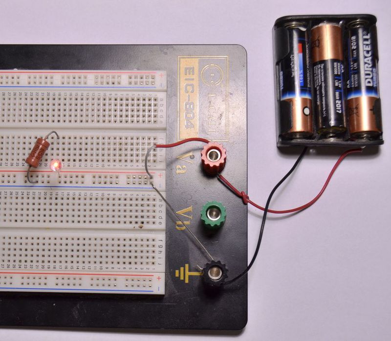
Batteries are connected to the red (+) and black (-) terminals, from which jumpers stretch to the power lines. Then a resistor is connected from the negative line to sockets No. 18, on the other hand an LED is connected to the same sockets by a cathode (short leg). The anode of the LED is connected to the positive line. I won’t go into the principle of the scheme’s operation and explain Ohm’s law - if you just want to play around, then this is not necessary, but if it’s still interesting, you can ask Google .
Maybe this is a rather sharp transition - from LED to microchips, but in terms of implementation, I do not see any difficulties.
So, there is such an LM7805 microcircuit (or just 7805), any voltage from 7.5V to 25V is supplied to it, and we get 5V at the output. There are others, for example, the chip 7812 - 12V. Here is such a switching scheme:
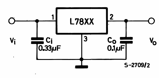
Capacitors are used to stabilize the voltage and, if desired, they can be omitted. This is how it looks in life:
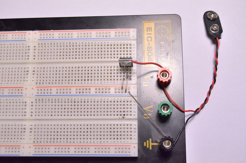
And close-up:
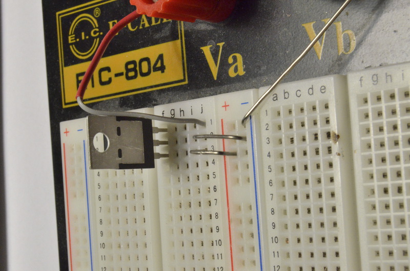
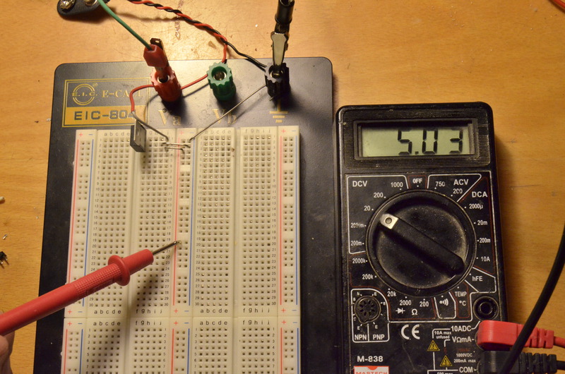
The pin numbering is from left to right, if you look at it from the marking side. In the photo, the pin numbering of the microcircuit matches the numbering of the bradboard connectors. The red terminal (+) is connected to the 1st leg of the microcircuit - input. The black terminal (-) is directly connected to the negative power line. The middle leg of the microcircuit (General, GND) is also connected to the negative line, and the third leg (Output) to the plus line. Now, if you apply 12V to the terminals, there should be 5V on the power lines. If there is no 12V power supply, you can take a 9V “Krona” battery and connect it through a special connector, shown in the photo above. I used a 12V power supply:

Regardless of the value of the input voltage, if it falls within the above limits, the output voltage will be 5V:
In conclusion, we add capacitors so that everything is according to the rules:

And now an example of using a different chip, but not in its most standard application. The chip 74HC00 or 74HCT00 is used, depending on the manufacturer, the name and after it can be different letters. Domestic analogue - K155LA3. Inside this microcircuit there are 4 logical elements “NAND” (Eng. “NAND”), each of the elements has two inputs, closing them together we get the element “NOT”. But in this case, the logic elements will be used in “analog mode”. The generator circuit is as follows:
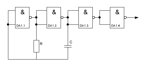
Elements DA1.1 and DA1.2 generate a signal, and DA1.3 and DA1.4 - form clear rectangles. The frequency of the generator is determined by the values of the capacitor and resistor and is calculated by the formula: f = 1 / (2RC). We connect any speaker to the output of the generator. If we take a 5.6 kΩ resistor and a 33nF capacitor, we get about 2.7 kHz - a kind of squealing sound. This is how it looks:
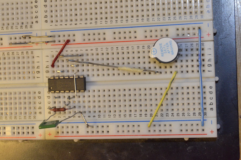
5V from the voltage regulator assembled earlier is connected to the top power lines in the photo. For ease of assembly, I will provide a verbal description of the compounds. The left half of the segment (bottom in the photo): The
capacitor is installed in slots No. 1 and No. 6;
Resistor - No. 1 and No. 5;
Jumpers are installed between the following sockets:
No. 1 and No. 2;
No. 3 and No. 4;
No. 4 and No. 5;
No. 7 and negative supply line.
The right half of the segment (top in the photo):
jumpers are installed between the following sockets:
No. 2 and No. 3;
No. 3 and No. 7;
No. 5 and No. 6;
No. 1 and "plus" nutrition;
No. 4 and “plus” dynamics;
In addition:
jumpers between connectors No. 6 of the left and right halves;
- between the left and right “minus” lines;
- between minus power and "-" dynamics;
the microcircuit is installed as in the photo - the first leg is in the first connector of the left half. The first leg of the microcircuit can be identified by the so-called key - a circle (as in the photo) or a semicircular cutout at the end. The remaining IC legs in the DIP packages are numbered counterclockwise.
If everything is assembled correctly, the speaker should beep when power is applied. By changing the values of the resistor and capacitor, you can follow the changes in frequency, but with a very large resistance and / or too small capacity, the circuit will not work.
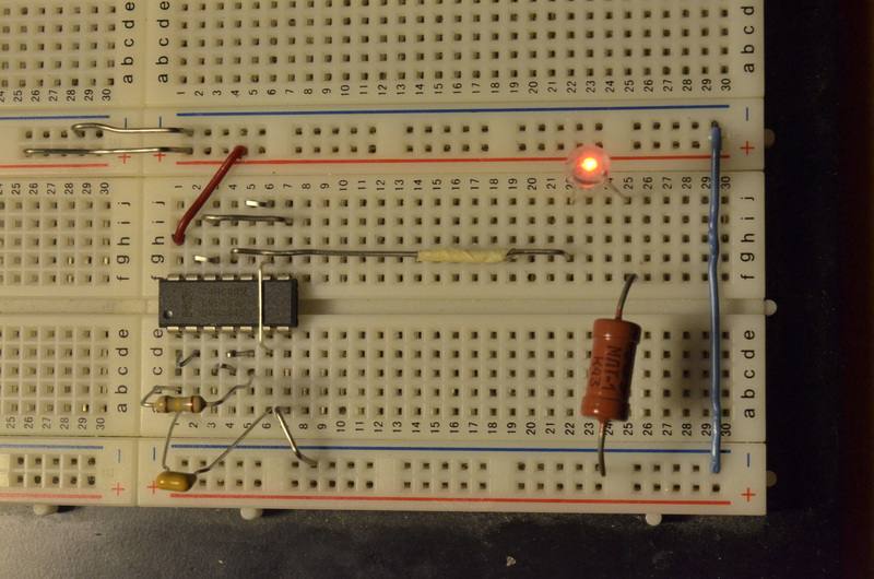
Now we change the resistor value to 180kΩ, and the capacitor to 1mkF - we get a clacking-ticking sound. We replace the speaker with a LED by connecting the anode (long leg) to the 4 connector of the right rug, and the cathode through the resistor 300 Ohm-1k Ohm to the power minus, we get a flashing LED that looks like this:
Now add another same generator so that we get such a circuit :
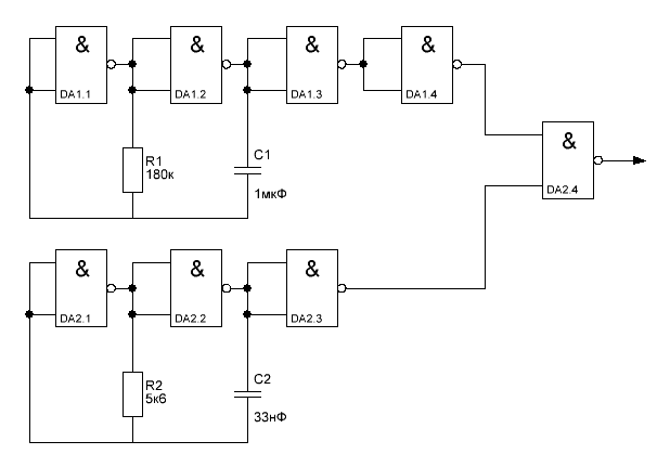
The generator on DA1 generates a low-frequency signal ~ 3Hz, DA2.1 - DA2.3 - high-frequency ~ 2.7kHz, DA2.4 - a modulatorthat mixes them. This is how the design should turn out:

Description of connections: The
left half of the segment (bottom in the photo):
Capacitor C1 is installed in slots No. 1 and No. 6;
Capacitor C2 - No. 11 and No. 16;
Resistor R1 - No. 1 and No. 5;
Resistor R2 - No. 11 and No. 15;
Jumpers are installed between the following sockets:
No. 1 and No. 2;
No. 3 and No. 4;
No. 4 and No. 5;
No. 11 and No. 12;
No. 13 and No. 14;
No. 14 and No. 15;
No. 7 and negative supply line.
No. 17 and minus power line.
The right half of the segment (top in the photo):
jumpers are installed between the following sockets:
No. 2 and No. 3;
No. 3 and No. 7;
No. 5 and No. 6;
No. 4 and No. 15;
No. 12 and No. 13;
No. 12 (13) and No. 17;
No. 1 and "plus" nutrition;
No. 11 and the “plus” of nutrition;
No. 14 and “plus” dynamics;
In addition:
jumpers between connectors No. 6 of the left and right halves;
jumpers between connectors No. 16 of the left and right halves;
- between the left and right “minus” lines;
- between minus power and "-" dynamics;
DA1 chip is installed in the same way as in the previous case - the first leg in the first connector of the left half. The second microcircuit - the first leg to connector No. 11.
If everything is done correctly, then when the power is applied, the speaker will start to emit three peaks every second. If you connect the LED (in parallel) to the same connectors, observing the polarity, you get such a device that reminds sounds of cool electronic gizmos from no less cool fighters:
This scheme is rather a tribute to traditions since in the old days, almost every novice amateur radio enthusiast collected such a thing.

In order to assemble a similar one, you need 2 BC547 transistors, 2 1.2kΩ resistors, 2 310Ω resistors, 2 22μF electrolytic capacitors and two LEDs. Capacities and resistances do not need to be observed exactly, but it is desirable that the circuit has two identical values.
On the board, the device looks as follows:
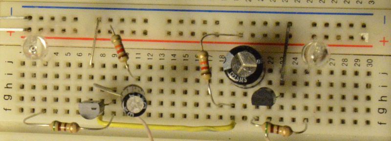
The transistor wiring is as follows:

B (B) base, C (K) collector, E (E) emitter.
For capacitors, the negative output is signed on the case ("+" was signed in Soviet capacitors).
Description of connections
The entire circuit is assembled on one (left) half of the segment.
Resistor R1 - No. 11 and "+";
resistor R2 - No. 19 and "+";
resistor R3 - No. 9 and No. 3;
resistor R4 - No. 21 and No. 25;
transistor T2 - emitter -№7, base - No. 8, collector - No. 9;
transistor T1 - emitter - No. 23, base - No. 22, collector - No. 21;
capacitor C1 - minus - No. 11, plus - No. 9;
capacitor C2 - minus - No. 19, plus - No. 21;
LED1 - cathode-3, anode - "+";
LED1 - cathode-25, anode - "+";
jumpers:
No. 8 - No. 19;
No. 11 - No. 22;
No. 7 - "-";
No. 23 - "-";
When applying a voltage of 4.5-12 V on the power line, something like this should turn out:
First of all, the article is aimed at those who want to "play around", so I did not give descriptions of the principles of operation of circuits, physical laws, etc. If anyone asks the question "why is it blinking?" - On the Internet you can find heaps of explanations with animations and other beautiful things. Someone may say that the bradboard is not suitable for the preparation of complex schemes, but what about this:

there are even more scary designs. As for the possible bad contact - when using parts with normal legs, the likelihood of poor contact is very small, I only had this a couple of times. In general, similar boards have surfaced here several times, but as part of the device built on Arduino. Honestly, I don't understand constructions like this:
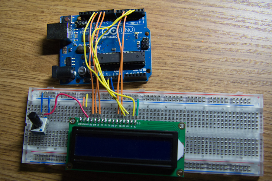
Why Arduino is needed at all, if you can take the programmer, flash the controller in the DIP-case and install it on the board, getting a cheaper, more compact and portable device.
Yes, some analog circuits sensitive to resistance and topology of conductors cannot be assembled on a breadboard, but they are not found so often, especially among beginners. But for digital circuits there are almost no restrictions.
PS: Cheat sheets for those taking the first steps
Not so long ago, an article about Arduino thundered here , spawning a holivar in the comments. Many Arduino supporters, they said, just want to collect something like flashing LEDs in order to diversify their leisure time and play. However, they do not want to bother with etching boards and soldering. As one of the alternatives, comrade dedsky mentioned the Znatok designer, but his capabilities are limited by the set of parts included in the kit, and the designer is still childish. I want to offer another alternative - the so-called Breadboard, a breadboard for mounting without soldering.
Caution, a lot of pictures.
What is it and what does it eat with
The main purpose of this board is to design and debug prototypes of various devices. This device consists of holes-nests with a pitch of 2.54 mm (0.1 inches), it is with this (or a multiple of it) pitch that the conclusions are located on most modern radio components (SMD does not count). Development boards come in various sizes, but in most cases they consist of these identical blocks:
The electrical connection diagram of the sockets is shown in the right figure: five holes on each side, in each of the rows (in this case 30) are electrically connected to each other. On the left and on the right there are two power lines: here all the holes in the column are interconnected. The slot in the middle is designed for installation and convenient removal of microcircuits in DIP packages. To assemble the circuit, radio components and jumpers are inserted into the holes, since I got the board without factory jumpers - I made them from metal paper clips, and small ones (to connect adjacent sockets) from staples for staplers.
It may seem that the larger the board - the greater its functionality, this is not entirely true. A very small chance that someone (especially from beginners) will assemble a device that will occupy all segments of the board, here are several devices at the same time - yes. For example, here I collected electronic ignition on a microcontroller, a multivibrator on transistors and a frequency generator for an LC meter:
So what can you do about it?
To justify the title of the article, I will cite several devices. A description of what and where to insert will be on the images.
Irreplaceable parts
In order to assemble one of the circuits described below, you will need a breadboard type board and a set of jumpers. In addition, it is desirable to have a suitable power source, in the simplest case, the battery (s), for the convenience of its connection (s) it is recommended to use a special container. You can use the power supply, but in this case you need to be careful and try not to burn anything, since the PSU is much more expensive than the batteries. Other details will be given in the description of the circuit itself.
LED connection
One of the simplest designs. On the circuit diagrams it is depicted as follows:
Of the details you will need: a low-power LED, any resistor at 300Ω-1kΩ and a power supply at 4.5-5V. In my case, a powerful Soviet resistor (the first that came to hand) at 430 Ohms (as indicated by the inscription K43 on the resistor itself), and as a power source - 3 finger-type (AA type) batteries in a container: a total of 1.5V * 3 = 4, 5B.
On the board, it looks like this:
Batteries are connected to the red (+) and black (-) terminals, from which jumpers stretch to the power lines. Then a resistor is connected from the negative line to sockets No. 18, on the other hand an LED is connected to the same sockets by a cathode (short leg). The anode of the LED is connected to the positive line. I won’t go into the principle of the scheme’s operation and explain Ohm’s law - if you just want to play around, then this is not necessary, but if it’s still interesting, you can ask Google .
Linear Voltage Regulator
Maybe this is a rather sharp transition - from LED to microchips, but in terms of implementation, I do not see any difficulties.
So, there is such an LM7805 microcircuit (or just 7805), any voltage from 7.5V to 25V is supplied to it, and we get 5V at the output. There are others, for example, the chip 7812 - 12V. Here is such a switching scheme:
Capacitors are used to stabilize the voltage and, if desired, they can be omitted. This is how it looks in life:
And close-up:
The pin numbering is from left to right, if you look at it from the marking side. In the photo, the pin numbering of the microcircuit matches the numbering of the bradboard connectors. The red terminal (+) is connected to the 1st leg of the microcircuit - input. The black terminal (-) is directly connected to the negative power line. The middle leg of the microcircuit (General, GND) is also connected to the negative line, and the third leg (Output) to the plus line. Now, if you apply 12V to the terminals, there should be 5V on the power lines. If there is no 12V power supply, you can take a 9V “Krona” battery and connect it through a special connector, shown in the photo above. I used a 12V power supply:
Regardless of the value of the input voltage, if it falls within the above limits, the output voltage will be 5V:
In conclusion, we add capacitors so that everything is according to the rules:
Gate Pulse Generator
And now an example of using a different chip, but not in its most standard application. The chip 74HC00 or 74HCT00 is used, depending on the manufacturer, the name and after it can be different letters. Domestic analogue - K155LA3. Inside this microcircuit there are 4 logical elements “NAND” (Eng. “NAND”), each of the elements has two inputs, closing them together we get the element “NOT”. But in this case, the logic elements will be used in “analog mode”. The generator circuit is as follows:
Elements DA1.1 and DA1.2 generate a signal, and DA1.3 and DA1.4 - form clear rectangles. The frequency of the generator is determined by the values of the capacitor and resistor and is calculated by the formula: f = 1 / (2RC). We connect any speaker to the output of the generator. If we take a 5.6 kΩ resistor and a 33nF capacitor, we get about 2.7 kHz - a kind of squealing sound. This is how it looks:
5V from the voltage regulator assembled earlier is connected to the top power lines in the photo. For ease of assembly, I will provide a verbal description of the compounds. The left half of the segment (bottom in the photo): The
capacitor is installed in slots No. 1 and No. 6;
Resistor - No. 1 and No. 5;
Jumpers are installed between the following sockets:
No. 1 and No. 2;
No. 3 and No. 4;
No. 4 and No. 5;
No. 7 and negative supply line.
The right half of the segment (top in the photo):
jumpers are installed between the following sockets:
No. 2 and No. 3;
No. 3 and No. 7;
No. 5 and No. 6;
No. 1 and "plus" nutrition;
No. 4 and “plus” dynamics;
In addition:
jumpers between connectors No. 6 of the left and right halves;
- between the left and right “minus” lines;
- between minus power and "-" dynamics;
the microcircuit is installed as in the photo - the first leg is in the first connector of the left half. The first leg of the microcircuit can be identified by the so-called key - a circle (as in the photo) or a semicircular cutout at the end. The remaining IC legs in the DIP packages are numbered counterclockwise.
If everything is assembled correctly, the speaker should beep when power is applied. By changing the values of the resistor and capacitor, you can follow the changes in frequency, but with a very large resistance and / or too small capacity, the circuit will not work.
Now we change the resistor value to 180kΩ, and the capacitor to 1mkF - we get a clacking-ticking sound. We replace the speaker with a LED by connecting the anode (long leg) to the 4 connector of the right rug, and the cathode through the resistor 300 Ohm-1k Ohm to the power minus, we get a flashing LED that looks like this:
Now add another same generator so that we get such a circuit :
The generator on DA1 generates a low-frequency signal ~ 3Hz, DA2.1 - DA2.3 - high-frequency ~ 2.7kHz, DA2.4 - a modulatorthat mixes them. This is how the design should turn out:
Description of connections: The
left half of the segment (bottom in the photo):
Capacitor C1 is installed in slots No. 1 and No. 6;
Capacitor C2 - No. 11 and No. 16;
Resistor R1 - No. 1 and No. 5;
Resistor R2 - No. 11 and No. 15;
Jumpers are installed between the following sockets:
No. 1 and No. 2;
No. 3 and No. 4;
No. 4 and No. 5;
No. 11 and No. 12;
No. 13 and No. 14;
No. 14 and No. 15;
No. 7 and negative supply line.
No. 17 and minus power line.
The right half of the segment (top in the photo):
jumpers are installed between the following sockets:
No. 2 and No. 3;
No. 3 and No. 7;
No. 5 and No. 6;
No. 4 and No. 15;
No. 12 and No. 13;
No. 12 (13) and No. 17;
No. 1 and "plus" nutrition;
No. 11 and the “plus” of nutrition;
No. 14 and “plus” dynamics;
In addition:
jumpers between connectors No. 6 of the left and right halves;
jumpers between connectors No. 16 of the left and right halves;
- between the left and right “minus” lines;
- between minus power and "-" dynamics;
DA1 chip is installed in the same way as in the previous case - the first leg in the first connector of the left half. The second microcircuit - the first leg to connector No. 11.
If everything is done correctly, then when the power is applied, the speaker will start to emit three peaks every second. If you connect the LED (in parallel) to the same connectors, observing the polarity, you get such a device that reminds sounds of cool electronic gizmos from no less cool fighters:
Transistor Multivibrator
This scheme is rather a tribute to traditions since in the old days, almost every novice amateur radio enthusiast collected such a thing.
In order to assemble a similar one, you need 2 BC547 transistors, 2 1.2kΩ resistors, 2 310Ω resistors, 2 22μF electrolytic capacitors and two LEDs. Capacities and resistances do not need to be observed exactly, but it is desirable that the circuit has two identical values.
On the board, the device looks as follows:
The transistor wiring is as follows:
B (B) base, C (K) collector, E (E) emitter.
For capacitors, the negative output is signed on the case ("+" was signed in Soviet capacitors).
Description of connections
The entire circuit is assembled on one (left) half of the segment.
Resistor R1 - No. 11 and "+";
resistor R2 - No. 19 and "+";
resistor R3 - No. 9 and No. 3;
resistor R4 - No. 21 and No. 25;
transistor T2 - emitter -№7, base - No. 8, collector - No. 9;
transistor T1 - emitter - No. 23, base - No. 22, collector - No. 21;
capacitor C1 - minus - No. 11, plus - No. 9;
capacitor C2 - minus - No. 19, plus - No. 21;
LED1 - cathode-3, anode - "+";
LED1 - cathode-25, anode - "+";
jumpers:
No. 8 - No. 19;
No. 11 - No. 22;
No. 7 - "-";
No. 23 - "-";
When applying a voltage of 4.5-12 V on the power line, something like this should turn out:
Finally
First of all, the article is aimed at those who want to "play around", so I did not give descriptions of the principles of operation of circuits, physical laws, etc. If anyone asks the question "why is it blinking?" - On the Internet you can find heaps of explanations with animations and other beautiful things. Someone may say that the bradboard is not suitable for the preparation of complex schemes, but what about this:
there are even more scary designs. As for the possible bad contact - when using parts with normal legs, the likelihood of poor contact is very small, I only had this a couple of times. In general, similar boards have surfaced here several times, but as part of the device built on Arduino. Honestly, I don't understand constructions like this:
Why Arduino is needed at all, if you can take the programmer, flash the controller in the DIP-case and install it on the board, getting a cheaper, more compact and portable device.
Yes, some analog circuits sensitive to resistance and topology of conductors cannot be assembled on a breadboard, but they are not found so often, especially among beginners. But for digital circuits there are almost no restrictions.
PS: Cheat sheets for those taking the first steps