Blade Switching in the Dell PowerEdge M1000e Chassis
Today we’ll talk about the Dell Networking MXL and PowerEdge MI / O Aggregator switches for installation in a modular chassis for Dell PowerEdge M1000e blade servers designed for high-speed communication between servers within the chassis and with neighboring server groups, storage systems and for connecting to the core of the network. They support the latest technologies for switching systems and, therefore, can be used as part of complex network architectures not only to increase the speed of data exchange and create fault-tolerant configurations, but also to converge transmission and storage networks. Each of them provides a performance of 1.28 Tbit / s in duplex mode, supports up to 6 40 Gbit / s ports and is equipped with two slots for installing expansion modules that support various network interfaces. However, as the name implies, one of them belongs to the Dell Networking line of network equipment, and the other to the Dell PowerEdge server. Why - we will understand when studying them. Let's start with the blade chassis.
The PowerEdge M1000e modular chassis for server blades is currently the company's flagship blade server market. Flexibility of configuration, compactness, centralized management, the ability to increase capacity during operation and implementation of new technologies without the complete re-equipment of server cabinets are the main advantages of using solutions based on blade technology. It has been developing for a long time, and the PowerEdge M1000e is a mature, complete solution with a wide selection of options for configuration. Briefly consider its device.
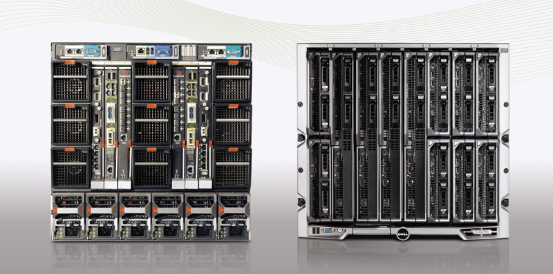
On the front side there are sixteen compartments for installing half-height servers, as well as other compatible devices. For example, Dell is releasing iSCSI storage systems for installation directly on this chassis. The most popular server format is half-height, as in the photo, however, there are both full-height and quarter-slots. Thus, it is possible to install up to 32 servers in one 10U chassis. Also on the front panel is an interactive mini-display and USB and VGA ports for connecting a keyboard, mouse and display.
On the back there are six compartments for power supplies (bottom) and nine for fans, all hot-swappable. On top are KVMs with the ability to connect to a remote console by twisted pair cable and two compartments for the Chassis Management Controller, which provides an interface for complete control of both the chassis and the equipment installed in it. Between the fans are six compartments for installing network switches.
The main part of the basket is midplay, through it the installed equipment is powered and data is exchanged. Each server has network ports preinstalled with LOM or added using expansion cards of the Mezzanine format, on the switches for the basket there are internal ports, all of them are switched via midplay. The data exchange rate on it can reach 8.4 Tbps in duplex mode. By installing the appropriate network switches, up to 32 internal server ports per slot are supported.
As a choice, Dell offers a dozen devices of varying degrees of complexity and power, as well as supporting different switching technologies. These are in-house Ethernet switches and Cisco, Fiber Channel switches Brocade and InfiniBand from Mellanox.

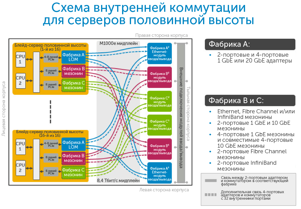
The following figure shows the port allocation for using four-port Ethernet adapters in servers using blade switches with 32 internal ports, such as the Dell Networking MXL.

Optical ports support both the connection of transceivers for subsequent switching with fiber optic cables, and direct connection with a special cable that supports a speed range of 10 Gbit / s or 40 Gbit / s, but is not intended for signal transmission over long distances. 40 Gb / s splitter cables in 4 to 10 Gb / s are available as options. The figure shows the supported expansion modules, transceivers, and cables for them.

A module with four 10GBASE-T RJ-45 ports can be installed only one, in the second slot you can put any other expansion module. In addition to this limitation, all other modules can be used simultaneously in any available combinations, both different and identical.

By default, all switch ports are active and all VLANs on them are tagged. If you need to define some ports untagged in this VLAN, this can be done through a simple graphical interface provided by the SMS module. This, however, does not mean that finer configuration of the device is not possible - it supports a wide range of features, a command line for administration is available.
MXL supports stack organization, which can include up to six devices, both located inside the same M1000e enclosure, and in different enclosures.
In addition to fault tolerance, this gives a high speed of data exchange between servers in different buildings and the ability to access switches on the stack as a single network device, with a single network address and general settings. The connection is carried out according to the "ring" technology, i.e. the first and last member of the assembly must be interconnected.
If the case is single, then both types of blade switches can support the stack created within the same M1000e for redundancy and load balancing. Such a stack is called horizontal — the cables in it are located exactly like that. A vertical stack is called a stack containing up to 6 MXL switches installed in three different chassis as part of a single rack. It is organized as a "ring". All equipment located in three M1000s within the rack, in the case of such a connection, becomes part of a single physical network, the aggregator of which is the MXL stack. From the outside, the switches that enter the stack generally look like a single device, with the same settings, providing a single set of services and even having one IP address. However, in terms of fault tolerance,

An alternative to the resilience-enhancing stack is the use of Dell Virtual Link Trunking (VLT) functionality on two MXL switches in the blade chassis (we wrote about this in detail here ). Then the blade servers in the chassis can be connected to two MXLs using the NAC LACP NIC, and rack switches can connect to two blade switches in the chassis using only one LAG. Typically, on MXL, two built-in 40 GbE ports combined in a LAG are used to organize the VLTi link.
The following feature of the stack must be considered. When updating DNOS software on the stack, all stack switches will be overloaded. This procedure must be performed during off-peak hours. If this is unacceptable, it is recommended to use Virtual Link Trunking (VLT) technology instead of stacking.
Switch Preparation:
Next, you need to put the switch ports in stacking mode.
Verify that the stacking ports are not yet configured on the MXL-A1 switch:
Typically, two integrated 40 GbE ports are used for stacking. These are fortyGig ports 0/33 and 0/37. The correspondence of the physical ports of the switch to stack-group numbers is shown in the figure below:

For deterministic selection of the stack master, it is recommended to prioritize each switch participating in the stack. The master with the highest priority becomes the master:
Verify that the stacking ports are not yet configured on the MXL-A2 switch:
Configure the stacking ports and priority on the MXL-A2 switch:
After that, you need to save the configuration and reboot both switches:
Wait until the switches reboot and connect the two stacking ports between the switches with 40GbE QSFP + Direct Attach cables or optical transceivers and optical cables:
fortyGig 0/33 on the MXL-A1 switch <-> fortyGig 0/33 on the MXL-A2
switch fortyGig 0/37 on the MXL switch -A1 <-> fortyGig 0/37 on the MXL-A2 switch
Verify on the stack master that the switches are stacked:
For more information on stacking MXL switches, see this document .
In general, MXL and MI / O are similar not only externally.
Both of these switches support FCoE convergence in FCoE transit mode, and when installing a module with FC ports, the ability to connect to an existing FC factory in NPIV Proxy Gateway mode, or for small installations like “Data Center in a Box” support FC storage connection directly (see figure) . Using convergence can save on HBAs in blade servers and FC blade switches in the chassis.

PowerEdge M1000e Enclosure
Acquaintance
The PowerEdge M1000e modular chassis for server blades is currently the company's flagship blade server market. Flexibility of configuration, compactness, centralized management, the ability to increase capacity during operation and implementation of new technologies without the complete re-equipment of server cabinets are the main advantages of using solutions based on blade technology. It has been developing for a long time, and the PowerEdge M1000e is a mature, complete solution with a wide selection of options for configuration. Briefly consider its device.
On the front side there are sixteen compartments for installing half-height servers, as well as other compatible devices. For example, Dell is releasing iSCSI storage systems for installation directly on this chassis. The most popular server format is half-height, as in the photo, however, there are both full-height and quarter-slots. Thus, it is possible to install up to 32 servers in one 10U chassis. Also on the front panel is an interactive mini-display and USB and VGA ports for connecting a keyboard, mouse and display.
On the back there are six compartments for power supplies (bottom) and nine for fans, all hot-swappable. On top are KVMs with the ability to connect to a remote console by twisted pair cable and two compartments for the Chassis Management Controller, which provides an interface for complete control of both the chassis and the equipment installed in it. Between the fans are six compartments for installing network switches.
The main part of the basket is midplay, through it the installed equipment is powered and data is exchanged. Each server has network ports preinstalled with LOM or added using expansion cards of the Mezzanine format, on the switches for the basket there are internal ports, all of them are switched via midplay. The data exchange rate on it can reach 8.4 Tbps in duplex mode. By installing the appropriate network switches, up to 32 internal server ports per slot are supported.
As a choice, Dell offers a dozen devices of varying degrees of complexity and power, as well as supporting different switching technologies. These are in-house Ethernet switches and Cisco, Fiber Channel switches Brocade and InfiniBand from Mellanox.
External switching
The diagram shows that two slots A on the chassis are for Ethernet switches, while B and C can contain modules with support for Fiber Channel and InfiniBand. Also here are two, for protection against failures, CMC modules connected to a dedicated control network. One module provides full functionality, the second is in hot standby. Between them is KVM, on which the RJ-45 port is not for connecting to a network, but for a remote console. Two USB and VGA - for local.Internal switching
The figure shows the internal switching diagram for half-height servers. The interfaces that may be present on such servers are shown here: an integrated two- or four-port Ethernet adapter with support for 1 or 10 Gbit / s speed and Mezzanine format expansion cards that can support up to two Fiber Channel and InfiniBand ports or up to four ports EthernetThe following figure shows the port allocation for using four-port Ethernet adapters in servers using blade switches with 32 internal ports, such as the Dell Networking MXL.
Dell Networking MXL and PowerEdge MI / O Aggregator
General
Both switches support up to 32 internal 10 GbE ports for communication between servers. Both are equipped with two 40 GbE QSFP + ports and two expansion slots for compatible modules. On the front panel of each there are 2 USB ports - one for the console and one for the storage device.Optical ports support both the connection of transceivers for subsequent switching with fiber optic cables, and direct connection with a special cable that supports a speed range of 10 Gbit / s or 40 Gbit / s, but is not intended for signal transmission over long distances. 40 Gb / s splitter cables in 4 to 10 Gb / s are available as options. The figure shows the supported expansion modules, transceivers, and cables for them.
A module with four 10GBASE-T RJ-45 ports can be installed only one, in the second slot you can put any other expansion module. In addition to this limitation, all other modules can be used simultaneously in any available combinations, both different and identical.
Differences
PowerEdge MI / O Aggregator
Designed for quick commissioning of the M1000e chassis and connection to networks built on the basis of equipment from various manufacturers that supports different network technologies. For commissioning, you need to unpack the switch, install it in the chassis slot, assign an IP address and an administrator password, and connect the uplink ports to the rack switch or network core switch. On the rack switch, you need to configure LAG in LACP mode. When convergence is used, all new DCB settings (ETS and PFC) will be taken by the new MI / O Aggregator from the rack switch using the DCBX protocol. To get started, you do not need to install additional licenses or pre-configure the blade switch.By default, all switch ports are active and all VLANs on them are tagged. If you need to define some ports untagged in this VLAN, this can be done through a simple graphical interface provided by the SMS module. This, however, does not mean that finer configuration of the device is not possible - it supports a wide range of features, a command line for administration is available.
Dell Networking MXL
The switch supports the dynamic routing protocols available in the Dell Networking Operating System 9 (OS9). It is an operating system that is fully compliant with industry standards and is managed through the command line and provides the administrator with a wide range of fine-tuning options. It is similar to Cisco IOS and supports PVST + for integration with it.MXL supports stack organization, which can include up to six devices, both located inside the same M1000e enclosure, and in different enclosures.
In addition to fault tolerance, this gives a high speed of data exchange between servers in different buildings and the ability to access switches on the stack as a single network device, with a single network address and general settings. The connection is carried out according to the "ring" technology, i.e. the first and last member of the assembly must be interconnected.
If the case is single, then both types of blade switches can support the stack created within the same M1000e for redundancy and load balancing. Such a stack is called horizontal — the cables in it are located exactly like that. A vertical stack is called a stack containing up to 6 MXL switches installed in three different chassis as part of a single rack. It is organized as a "ring". All equipment located in three M1000s within the rack, in the case of such a connection, becomes part of a single physical network, the aggregator of which is the MXL stack. From the outside, the switches that enter the stack generally look like a single device, with the same settings, providing a single set of services and even having one IP address. However, in terms of fault tolerance,
An alternative to the resilience-enhancing stack is the use of Dell Virtual Link Trunking (VLT) functionality on two MXL switches in the blade chassis (we wrote about this in detail here ). Then the blade servers in the chassis can be connected to two MXLs using the NAC LACP NIC, and rack switches can connect to two blade switches in the chassis using only one LAG. Typically, on MXL, two built-in 40 GbE ports combined in a LAG are used to organize the VLTi link.
MXL Stack Configuration Example
This example shows a stack configuration using two MXL switches in factory A1 (MXL-A1) and A2 (MXL-A2), stacked on two fortyGig ports 0/33 and 0/37.The following feature of the stack must be considered. When updating DNOS software on the stack, all stack switches will be overloaded. This procedure must be performed during off-peak hours. If this is unacceptable, it is recommended to use Virtual Link Trunking (VLT) technology instead of stacking.
Switch Preparation:
- If the DNOS versions on the switches are different, you must upgrade them so that all switches on the stack have the same version of DNOS. Checking Version Using the Command
show version
. - Switches must be loaded.
- Stacking cables must not be connected.
Next, you need to put the switch ports in stacking mode.
Verify that the stacking ports are not yet configured on the MXL-A1 switch:
MXL-A1 # sho system stack-ports
Topology: Stand alone
Interface Connection Link Speed Admin Link Trunk
(Gb / s) Status Status Group
-------------------------------------------------- ----------------Typically, two integrated 40 GbE ports are used for stacking. These are fortyGig ports 0/33 and 0/37. The correspondence of the physical ports of the switch to stack-group numbers is shown in the figure below:
 MXL-A1 (conf) # stack-unit 0 stack-group 0
MXL-A1 (conf) # stack-unit 0 stack-group 1
For deterministic selection of the stack master, it is recommended to prioritize each switch participating in the stack. The master with the highest priority becomes the master:
MXL-A1 (conf) # stack-unit 0 priority 14
Verify that the stacking ports are not yet configured on the MXL-A2 switch:
MXL-A2 # sho system stack-ports
Topology: Stand alone
Interface Connection Link Speed Admin Link Trunk
(Gb / s) Status Status Group
-------------------------------------------------- ----------------Configure the stacking ports and priority on the MXL-A2 switch:
MXL-A2 (conf) # stack-unit 0 stack-group 0
MXL-A2 (conf) # stack-unit 0 stack-group 1
MXL-A2 (conf) # stack-unit 0 priority 1
After that, you need to save the configuration and reboot both switches:
MXL-A1 # wr
MXL-A1 # reload
MXL-A2 # wr
MXL-A2 # reload
Wait until the switches reboot and connect the two stacking ports between the switches with 40GbE QSFP + Direct Attach cables or optical transceivers and optical cables:
fortyGig 0/33 on the MXL-A1 switch <-> fortyGig 0/33 on the MXL-A2
switch fortyGig 0/37 on the MXL switch -A1 <-> fortyGig 0/37 on the MXL-A2 switch
Verify on the stack master that the switches are stacked:
MXL-A1 # sho system brief
Stack MAC: d0: 67: e5: cc: 8e: f0
Reload Type: normal-reload [Next boot: normal-reload]
- Stack Info -
Unit UnitType Status ReqTyp CurTyp Version Ports
-------------------------------------------------- ----------------------------------
0 Management online MXL-10 / 40GbE MXL-10 / 40GbE 8.3.16.4 56
1 Standby online MXL-10 / 40GbE MXL-10 / 40GbE 8.3.16.4 56
2 Member not present
3 Member not present
4 Member not present
5 Member not present
MXL-A1 # sho system stack-ports
Topology: Ring
Interface Connection Link Speed Admin Link Trunk
(Gb / s) Status Status Group
-------------------------------------------------- ----------------
0/33 1/37 40 up up
0/37 1/33 40 up up
1/33 0/37 40 up up
1/37 0/33 40 up upFor more information on stacking MXL switches, see this document .
If simplicity is not the main thing, then there are more possibilities
As for the impossibility of organizing a stack of six MI / O Aggregator, a clarification should be made - with the basic settings out of the box. When reconfiguring via the command line, four operating modes are available for them:- Standalone mode (SMUX) is the default mode with a simple configuration.
- VLT mode - the member mode of the VLT domain, which we talked about earlier.
- Programmable MUX mode (PMUX) - fully configurable via the command line mode, with the possibility of flexible settings.
- Stack mode - stack support mode using the “ring” technology, up to six devices on the stack.
In general, MXL and MI / O are similar not only externally.
A few words from the practice of editing
Let us explain some terms and magic numbers. The height of the M1000e is 10U, they are suitable for tight installation. Under HPC (High Performance Computing) conditions, free space in the server room and in each cabinet is just as valuable and as fast running out as free space on the hard drive of a work computer. Therefore, it is considered good practice to use racks and cabinets with a height of 42U-47U. The stance as a whole is usually in some way a self-sufficient unit, even when it is far from alone. Therefore, the heaviest equipment is mounted down - the UPS, which usually takes up to 10U. Next are the server enclosures, and the M1000e fits just 3 pieces. Optionally, at a height of 20U for such an installation, a console 1U high can be installed, a retractable one, for direct work with servers and other equipment. As we notedConvergence
Since both switches under consideration support FCoE and expansion cards with FC ports and can directly work with storage systems supporting this data transfer protocol, when using them, it is possible to directly connect these storage systems to a common converged network.Both of these switches support FCoE convergence in FCoE transit mode, and when installing a module with FC ports, the ability to connect to an existing FC factory in NPIV Proxy Gateway mode, or for small installations like “Data Center in a Box” support FC storage connection directly (see figure) . Using convergence can save on HBAs in blade servers and FC blade switches in the chassis.
MXL Switch Configuration Example
In conclusion, we would like to give an example of a working configuration of the Dell Networking MXL blade switch installed in the Dell PowerEdge M1000e chassis.The example will be useful to technicians who are the first to configure Dell switches running Dell Networking OS 9.x for L2 scenarios.
Comments in the text are in italics.
MXL-A1 # show running-config
Current Configuration ...
! Version 9.8 (0.0)
[Specified version of Dell Networking OS running the switch]
! Last configuration change at Thu Jul 23 17:49:01 2015 by default
! Startup-config last updated at Sat May 16 04:52:23 2015 by default
!
boot system stack-unit 0 primary system: A:
boot system stack-unit 0 secondary system: B:
[The Dell switch is assigned the number “stack-unit”. When Dell switches do not stack, they are numbered “0”. If the switches are stacked, their number will be indicated in accordance with the position in the stack: from 0 to 5.
The boot system command indicates two partitions: A and B. Each partition can have its own version of Dell Networking OS. “A” is the primary and “B” is the backup partition. Upon boot, the switch automatically downloads the version of Dell Networking OS in the main partition, unless otherwise specified in the boot system command.
In Dell Networking OS, after a command is entered, its action is applied in the current (running) configuration file. To save the current configuration, copy the running configuration to another location (for example, to the non-volatile memory of the switch using the copy running startup command).]
!
redundancy auto-synchronize full
[Set by default. Used when stacking for the duration of the stack master synchronization with the backup switch.]
!
hostname MXL-A1
!
!
username admin password 7 888dc89d1f1bca2882895c1658f993e7 privilege 15
username root password 7 d7acc8a1dcd4f698 privilege 15 role sysadmin
[Create local administrator accounts. Dell Networking OS also supports authentication and authorization on RADIUS and TACACS + servers. Because the “enable” or “enable secret” password command is not specified, the network administrator will immediately enter privileged exec mode (hostname #) after successfully entering the password.]
!
default vlan-id 11
[Assign VLAN 11 as native / untagged / default VLAN. Native VLAN - Untagged.]
!
!
protocol spanning-tree rstp
no disable
bridge-priority 57344
[Configuring the RSTP 802.1w protocol. Dell Networking OS 9.x also supports PVST +, MST (802.1s) and STP (802.1D).
If the 802.1w RSTP domain of the Dell switches is connected to the Rapid-PVST + domain of the Cisco switches, VLAN 1 must be enabled on both sides of the trunk port (or Port-channel) connecting the Dell and Cisco switches. This will allow the RSTP domain to converge using the Common Spanning Tree (CST), which uses VLAN 1.
On Cisco IOS and NX-OS, VLAN 1 is the only VLAN that allows Cisco rapid-PVST + to communicate with other switches using RSTP 802.1w. Only in VLAN 1 does the Cisco switch send Cisco proprietary BPDUs and also standard BPDUs for convergence of topology with other switches. The 802.1w-enabled switch uses standard BPDUs in VLAN 1. Proprietary Cisco BPDUs are tunneled through a network of third-party switches to the next Cisco switch to ensure Cisco PVST + protocol convergence.]
!
no iscsi enable
[This command disables iSCSI optimization on Dell switches — these are Jumbo MTU, flow control, unicast storm control, and others, which is enabled by default on Dell Networking OS.]
!
vlt domain 2
peer-link port-channel 10
back-up destination 192.168.2.2
primary-priority 57344
system-mac mac-address 02: 01: e8: 00: 01: 02
unit-id 0
[These commands configure the Dell Virtual Link functionality Trunking (VLT), implementation of Multi-chassis LAG technology. VLT allows you to combine two switches into a fault-tolerant configuration for connecting to other switches or servers using the Link Aggregation Group (LAG) and 802.3ad LACP protocol. Because physical ports belong to one Port-channel logical interface, the Spanning Tree protocol does not block individual ports and provides balancing across all physical ports in the group.
Two VLT switches form a domain with number 1. The link connecting two VLT switches to each other, under the name VLTi, consists in this example of 2 40G ports (Fo0 / 33 and Fo0 / 37), combined in a port-channel under number 10 ( You can use any number in the range from 1 to 128). VLTi link is used to synchronize service information and all tables (MAC addresses and ARP tables, IGMP, etc.). This allows two VLT switches to function as one logical switch for devices connected to them. One of the switches assumes the role of VLT primary (can be set using the primary-priority command), and the second role is secondary, this role further determines the behavior of the switch in case of network failure scenarios, as well as for processing STP BPDUs.
As the back-up destination IP address, the management address of the VLT interface of the neighbor is used. When you create a VLT domain on switches, Dell Networking OS can itself assign a MAC address for communication and give the switches a unique unit ID. Using the system-mac mac-address and unit-id commands minimizes the synchronization time of VLT neighbors after rebooting one of the switches.]
!
stack-unit 0 provision MXL-10 / 40GbE
!
stack-unit 0 port 41 portmode quad
!
stack-unit 0 port 45 portmode quad
[The built-in 40GE MXL switch ports (Fo0 / 33 and Fo0 / 37) operate in 40GE mode by default. They are often used for stacking or for the VLTi link in the case of VLT technology. By default, 40GE ports on the 2-port expansion module for the MXL switch operate in 8 x 10GE mode (quad mode). If you plan to use these ports for stacking, you need to convert them to 40GE mode.
To transfer from 4-port 10GE mode to 40GE mode, the following commands are used:
switch (conf) # no stack-unit <switch number on the stack> port < port number 40GE (33, 37, 41, 45, 49 or 53> portmode quad ]
stack-unit<switch number on the stack>: specify the number of the switch on the stack in the range 0-5. To display the switch number on the stack, use the show system brief command .
port <40G port number>: enter the 40GE QSFP + port number. Numbers of the built-in ports 40GE of the MXL switch: 33 or 37; port numbers for expansion slot slot 0: 41 or 45; for expansion slot 1: 49 or 53
portmode quad : indicates that the 40GE port is operating in 4 x 10GE mode.]
!
!
!
interface TenGigabitEthernet 0/1
description internal server
no ip address
portmode hybrid
[Allows the port to switch tagged and untagged VLANs. Corresponds to the Cisco “switchport mode trunk” command]
switchport
[Defines the port as Layer 2]
spanning-tree rstp edge-port
[Allows the port to skip the STP Listening and Learning phases and immediately switch to STP Forwarding mode. Used on the ports to which the servers are connected. Corresponds to the Cisco “portfast” command in Cisco IOS]
no shutdown
!
!
!
interface fortyGigE 0/33
description port-channel_member_10
no ip address
no shutdown
!
interface fortyGigE 0/37
description port-channel_member_10
no ip address
no shutdown
!
!
!
interface fortyGigE 0/49
description member port-channel 1
no ip address
port-channel-protocol LACP
port-channel 1 mode active
[Adds port Fo0 / 49 to the port-channel 1 aggregation group and enables the LACP protocol for it to coordinate the settings of the LAG aggregation group between the switches.]
no shutdown
!
interface fortyGigE 0/53
description member port-channel 1
no ip address
port-channel-protocol LACP
port-channel 1 mode active
no shutdown
[Adds port Fo0 / 53 to the port-channel 1 aggregation group and enables LACP on it.
The same settings for a group of ports can be made using the range command:
switch (conf) #interface range fo0 / 49-53]
!
!
interface ManagementEthernet 0/0
ip address 192.168.2.2/24
no shutdown
[This is the port for the dedicated switch management network that is connected to the internal M1000e blade chassis management switch. The iDRAC blade server interfaces for management are connected to the same L2 switch. The Chassis Management Controller (CMC) chassis blade module has an external RJ-45 port for connecting to a dedicated management network.]
!
!
!
interface Port-channel 1
description Port-Channel to S6000 switches
no ip address
switchport
vlt-peer-lag port-channel 1
[Configures port channel 1 as an L2 port, as well as a VLT port-channel. VLT port-channel consists of physical ports that are distributed between two switches in the VLT domain, while all ports are active and traffic is balanced across all ports in the port-channel without blocking STP ports.]
No shutdown
!
!
!
interface Port-channel 10
description VLTi link to 450-MXL-A2
no ip address
channel-member fortyGigE 0 / 33.37
[This example shows the configuration of a static port channel without using the LACP protocol. VLTi port-channel should be configured just static.]
No shutdown
!
!
interface Vlan 1
no ip address
tagged TenGigabitEthernet 0 / 1-32
tagged Port-channel 1
[Defines VLAN 1 tagged on Te0 / 1-32 ports (these are ports to blade servers) and port-channel 1. It is not recommended to use VLAN 1 for any productive traffic, because it is used by control-level protocols such as STP.]
no shutdown
!
!
interface Vlan 2
description WAN_VLAN
no ip address
tagged TenGigabitEthernet 0 / 1-32
tagged Port-channel 1
[Defines VLAN 2 tagged on Te0 / 1-32 and port-channel 1.]
no shutdown
!
!
interface Vlan 11
description vlan 11
untagged TenGigabitEthernet 0 / 1-32
untagged Port-channel 10
[Defines VLAN 11 untagged on ports Te0 / 1-32 and port-channel 10. Untagged traffic coming to the switch will go to VLAN 11.]
!
!
[One of the differences between configuring switches running Dell Networking OS 9.x and Cisco switches is the configuration of the VLANs on the switch ports.
The configuration of VLAN 1, 2, and 11 above defines Te0 / 1-32 and port-channel 1 ports as trunk. VLANs 1 and 2 are tagged, and VLAN 11 is configured as a native / untagged VLAN. On Cisco switches, the equivalent command configuration is performed on physical ports or port-channel and looks like this:
interface Te0 / 1 (or Po1)
switchport mode trunk
switchport trunk allowed VLAN 1,2,11
switchport trunk native VLAN 11
If, for example, you need to configure the Te0 / 20 port as an access port in VLAN 100, you can do this on the Dell switch with the following commands:
interface VLAN 100
description HR_Department_LAN
untagged TenGigabitEthernet 0/20
On the Cisco switch, this is configured with the following commands:
interface TenGigabitEthernet 0/20
switchport mode access
switchport mode access VLAN 100
]
!
!
!
management route 0.0.0.0/0 192.168.2.1
[The default route for the management network with the next-hop IP address.]
!
ip domain-name dell.local
ip domain-lookup
[Setting the default domain name and enabling dynamic resolution for domain names.]
ip name-server ABCD
ip name-server EFGH
[Specifies the IP addresses of DNS servers to which requests will be sent to resolve domain host names.]
!
!
!
!
banner login ^ C
################################################## #############
# #
WARNING #
# #
# This is a private device and can only be accessed by #
# authorized personal. Use of this resource can be #
# monitored and unauthorized use is strictly prohibited. #
# #
#################################################### ############
^ C
!
ntp server ABCD
ntp server EFGH
[Server addresses for time synchronization using Network Time Protocol]
!
clock timezone GMT 3
[Defines the time zone GMT +3.]
ip ssh server version 2
[Enables the SSH server for remote management of the switch.]
!
no dcb enable
[Disables the Data Center Bridging functionality used in scripting for FCoE and iSCSI converged networks.]
!
!
!
protocol lldp
[Enables the Link Layer Discovery Protocol. Switches running Dell Networking OS 9.x support LLDP instead of Cisco CDP.]
!
!
line console 0
line vty 0
line vty 1
line vty 2
line vty 3
line vty 4
line vty 5
line vty 6
line vty 7
line vty 8
line vty 9
!
reload-type
boot-type normal-reload
[The switch is configured for normal boot mode. There is also an alternative boot mode called BMP, which allows the switch to automatically download the configuration file and OS from a remote server and simplifies the installation of a large number of switches. By default, the new switch operates in BMP boot mode. To switch to normal boot mode, on the command line of the switch, execute the following commands:
FTOS # stop bmp
FTOS # reload-type normal-reload
]
!
end