Recreation of the first trigger
- Transfer
The fundamental building block of modern digital schemes celebrates its centenary
Many engineers are familiar with the names of Lee de Forest , the inventor of the amplifying electron tube , Walter Brattein and William Shockley , the inventors of the transistor. However, few people know William Eccles and F.W. Jordan , who registered a patent for a trigger 100 years ago, in June 1918. A trigger is a key building block of digital circuits: it works as an electronic switch that can be set to the on or off position, in which it will remain even after the cessation of the control signal. This allows the circuits to memorize and synchronize their states, and therefore, to perform sequential logic operations.
The trigger was created before the digital era in the form of a relay for radio circuits. An article in the issue of The Radio Review of December 1919 told about its existence , and two decades later the trigger will be in the Colossus computer , created in England for hacking German military codes, and in the ENIAC computer in the United States.
Modern triggers in innumerable quantities are made of transistors in integrated circuits, but in honor of the century of the trigger I decided to reproduce the original scheme of Eccles and Jordan as close as possible to the original.
The contour is built on two electronic tubes, so I started with them. Eccles and Jordan most likely used Audion lamps or their British counterparts.Audion invented de Forrest , and it was the first electronic lamp that demonstrated amplification and allowed a weak signal applied to the grid to control a much stronger electric current flowing from the cathode to the anode. But the early lamps were made by hand and were unreliable, and today it would be impractical to acquire a working pair of such lamps.
Instead, I turned to the UX201A , an improved version of the UV201 , which General Electric began producing in the 1920s. By the time UV201 not far away from the original patent, noting the beginning of the mass production of vacuum tubes, which led to a jump in reliability and availability. I managed to order two 01A lamps for $ 35 apiece.
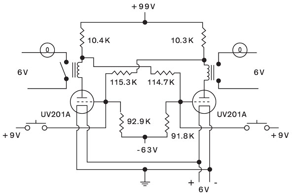

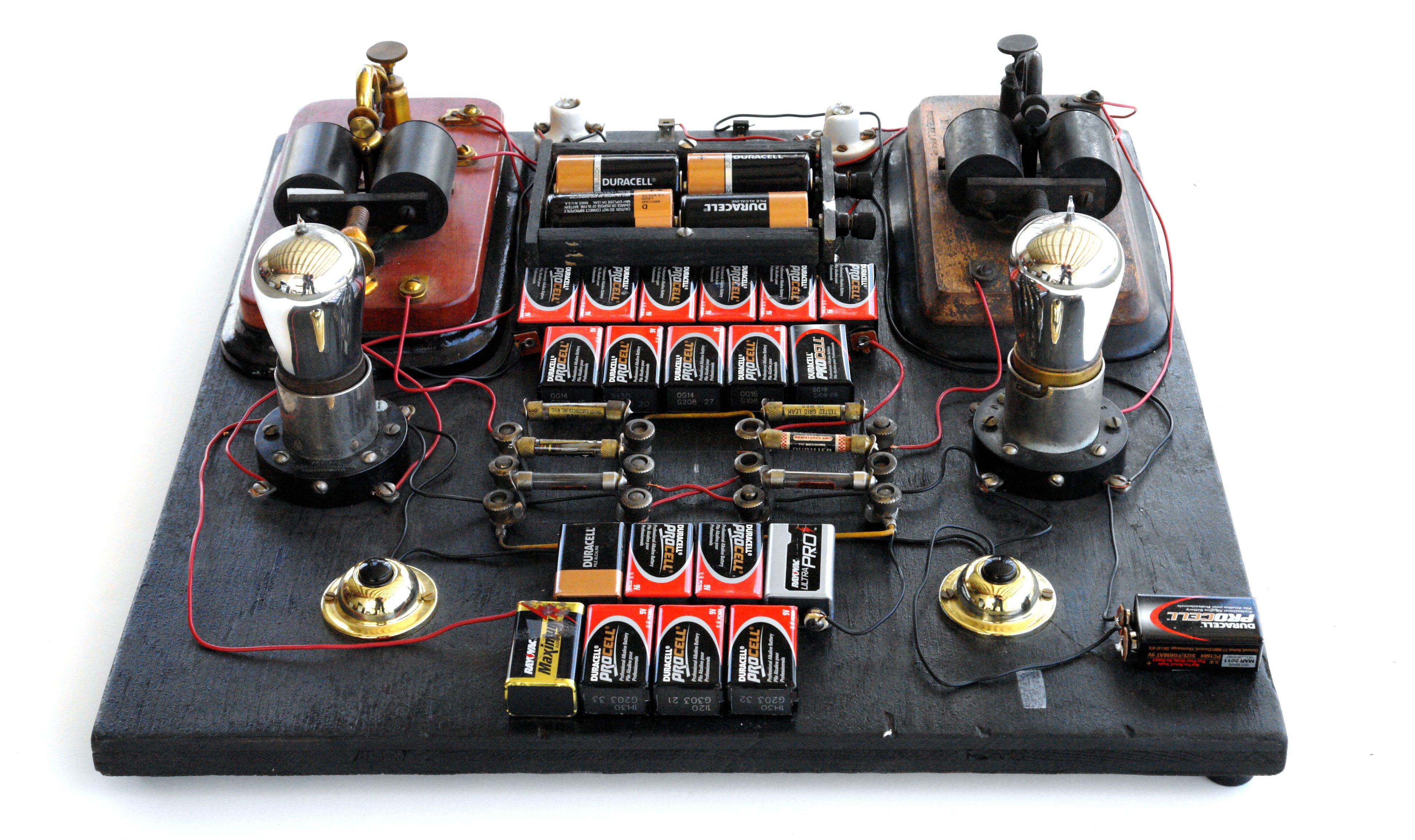
Working in drawings taken from various sources, including the patent of Eccles and Jordan (below), I recreated their scheme and selected resistance by trial and error (above).
In the trigger, the lamps are cross-connected so that a balance is maintained using a pair of resistors that control the voltage. Balancing means that turning off, even instant, one lamp, turns on the second, and keeps the first off. This state is maintained until the second lamp is turned off by the pilot signal, which causes the first lamp to turn on and the second one to keep it off.
To achieve the desired balance it was necessary to accurately select the values of the resistors. In the laboratory, Eccles and Jordan would use a tool called the resistor decade box, a bulky device that allows you to connect different resistances to different points of the circuit with the handle. For reasons of space, I decided to use fixed resistors of a model that is suitable for the patent.
I was able to get these resistors from the collection of vintage radios I collected over many years. In the 1920s, there was an explosive growth in the production of radio, with the result that I have quite a few old radio receivers that cannot be classified and restored, so I was not very upset about dismantling them for parts. Resistors, manufactured before 1925, were usually located in the sockets, and not soldered to the board, so it was not difficult to remove them.
The difficulty was that these resistors are terribly inaccurate. They were manually made of carbon located between the clamps in a glass case. One way to bring the resistance value to the desired one is to open the case, take out a strip of carbon, make notches on it to increase resistance, and insert it back. I corrected several resistors in this way, but for others it was too complicated, so I cheated and put modern resistors in vintage glass cases.
I used modern batteries in order not to get involved with liquid batteries, which the inventors probably used. One of the problems with lamp circuits is related to the need for several different voltages. Four batteries D, installed in series, give 6 V, necessary for indicator lamps and filaments. By sequentially connecting eleven 9V batteries, I got the 99V needed for the lamp plate. In a similar way, a 63 V power supply is required for negative grid bias current. Old-fashioned doorbell buttons allowed me to connect 9V for control pulses. To demonstrate the status of the trigger, I used sensitive vintage telegraph relays that control miniature incandescent lamps.
After many trials, errors and adjustments of my components, which are almost 100 years old, a year later, I finally managed to achieve stable operation of this venerable scheme!
If you want to repeat my achievement, and are ready to neglect historical accuracy in favor of simplifying the search for reliable components, then there are some good options. The 6J5 lamps , which first began to be produced in the late 1930s, are perfect . They are reliable and sold much cheaper than 01A, for $ 5- $ 7 apiece.
Telegraph relays and lamps can be replaced with inexpensive NE-2 neon lamps. They need to be connected between the 6J5 plates and the batteries, so that they light up when the lamp is not conducting, and go out when it conducts, lowering the plate voltage. Consider that 6J5 is an indirect-heating lamp, therefore the cathode must be grounded, and 6 V must be supplied separately to the heat, in contrast to the original circuit.
Selecting a battery for bias current will require experimentation, and for 6J5 it is likely that you will need less than 63 V used for 01A. As for the resistances used, their values must be considered approximate, and some efforts will have to be made to accurately match the three pairs.