Avionics Software Development
The development of avionics software is based on the fundamental standard RTCA \ DO-178B . Despite the first glance at his estrangement from the programmer’s immediate routine, he describes the entire development process and puts forward requirements for such software. Nevertheless, this article will also discuss how everything actually happens, based on personal experience in developing flight control and management systems, landing systems, etc. for airplanes and helicopters.

Modern solutions for the control and monitoring of aircraft control systems ( Flight Control System) Is a complex hardware-software complex, the work of which, perhaps, as a whole, is not known to any of the employees and developers. This is akin to the development of the atomic bomb of the Second World War, where everyone knows well part of their work, but does not really know why it works together. However, avionics is not the only example of such complex systems, and the complexity of the same Microsoft Excel or GNU GCC, of course, causes similar problems, but, nevertheless, for aviation software there are nuances and typical solutions that I will try to separately focus on. Facing the problem of effective management of the development process, management, trying to follow the optimization of cost parameters and project quality, creates an information and organizational deficit. It is connected, first of all, with a high cost of specialists and / or their training in the field of aviation software, i.e. with staff, as often in large projects, its number can reach about 2-3 thousand people per control system alone (not to mention the dynamic model and physical performance of the airframe, and especially the product). Secondly, with the organization of communication and the flow of information, its synchronization between development participants, as well as restrictions on excessively large amounts of data passing through one or another level. Therefore, for the development of such systems, a special, carefully documented and regulated technical process of developing requirements, creating hardware and software, implementing and debugging the system, as well as its testing and preparation of certification documentation was approved. Nonetheless,
To develop critical systems, it is necessary to ensure the minimum possibility of error (for the highest level in avionics, the probability of failure is 10 ^ -9), as well as to minimize the cost of developing and fixing the code. Due to the complexity of the system and the relationship with other parts (other software, other hardware), a waterfall model or agile development may not be the best option, therefore, a V-shaped development model is chosen as the fundamental principle for developing such software .
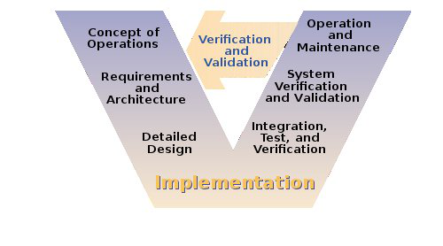
Figure 1. V-shaped development model.
First of all, such a model makes it possible to ensure synchronization of all project participants at each iteration, as well as provides the opportunity to use the already accumulated data and a ready methodology, because at the start of any project, the V-shaped model (Figure 1.) can be adapted to this project, since this model does not depend on the types of organizations and projects. V-model allows you to break down an activity into separate steps, each of which will include the actions necessary for it, instructions for them, recommendations and a detailed explanation of the activity. This is especially important for the multi-iteration cycle of development and testing of avionics software, as allows, in fact, to break directly the software development into separate sub-cycles. Usually a V-model is generalized to a spiral model.development (Fig. 2). Which, in turn, already allows you to assess the risks at each stage of development, as well as optimally distributes the workload of specialists (shortages of employees and time for short periods of time (Iteration Packages, synchronized with the V-shaped model in each Baseline).
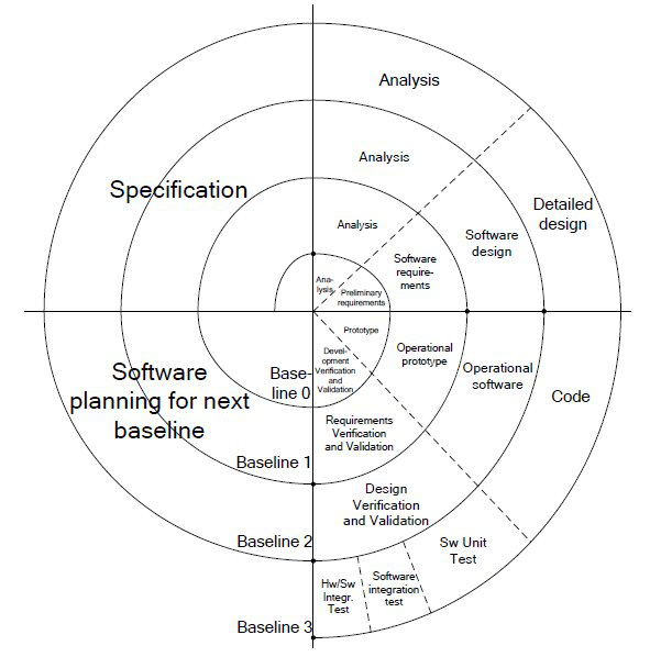
Figure 2. Spiral software development-testing model
To control each stage and for the subsequent possibility of certification, the process is divided into different levels, each of which has its own document for which a document is created that controls it (report). As a result, each stage of development, all errors and corrections are classified and documented. By repeating iterations of development each time, the probability of error is reduced. These documents are also created on the basis of the company's internal standards and requirements submitted by the customer.

Figure 3. Relationship of documents and requirements
Of course, everything is headed by the customer, who often doesn’t really know what he needs, but is quite capable of saying that he wants his plane to fly, has a taxiing and conditioning system for all occasions, and also that this system works the way he wants it, and even with bonuses. Therefore, the first part is an analysis of customer requirements and determination of the basic functionality of the system, on the basis of which a general concept and scheme of the system is created, including technical details of the equipment used, i.e. Create initial Equipment Specification and System Requirements.
When the base on which the system will be created is determined, the plan is approved according to which the software development plan and its certification (Qualification Plan - plan for Software Aspects of Certification) will go through. Despite the fact that the main thing for the customer is to get ready-made management software, a parallel process is the development of hardware, which cannot be ignored in software development, as Avionics software development is very closely related to hardware; for the most part, software is portable and embeddable, but highly dependent on the layout of the systems, but more on that later.
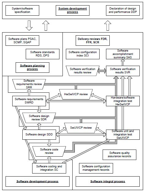
Fig 4. V-shaped model, divided into stages according to the statutory documents
Before moving on, it’s worth saying that the initial design is based on the fundamental principles that are present throughout the development process, and the main one is the “dissimilarity”, which determines that each part of the control system should be implemented by different groups of people on different hardware stuffing using different software tools (including development tools, programming languages). Thus, the system is divided into software and hardware independent parts, and the development process is controlled by different groups of people for different tasks and at different levels, respectively, in accordance with the higher requirements and plan.
The result of the initial design is a system model, usually performed in the Matlab \ Simulink, Labview environments. On the basis of the model, documents are created that regulate which hardware should be used and what communications they should have between themselves. At a minimum, the result of this stage is the creation of two documents: defining a hardware component (hardware) and software and hardware (hardware-software).
Next, the stage of the engineering process of preparation, assembly of boards and finished modules (Control Electronic, etc.) begins, i.e. Direct installation, wiring of the necessary microcontrollers, microcircuits, peripherals, for which the necessary software will be written. To interact with the hardware, there must be drivers and a framework layer on the basis of which the application should be built. Nevertheless, often the programmer’s work begins already when it is necessary to add the necessary drivers \ functionality, and most often make changes to the “comprehensive library” based on the HSI (Hardware-Software Interface) document. So, the most common practice is to "trim" the functionality of the system to the limit of the used hardware and drivers, as well as change some calibration settings,
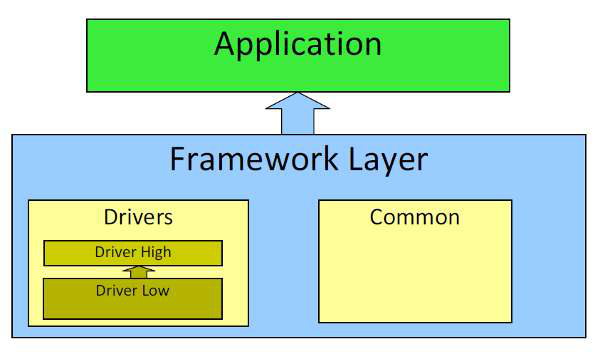
Figure 5. Software Organization
Accordingly, the universal library of the Framework includes all kinds of drivers for devices certified for use in aviation, as well as certified standard functions and procedures.
This is a fundamental point, because the most common strcmp function, for example, cannot be used directly, it must be rewritten in accordance with standards and certified. A set of such certified standard functions, prototypes, templates is Common in the Framework layer. This attitude is especially critical for safe mathematical operations (fast fractional division for integer processors, module, root, as an example), and for working with memory. All the algorithms, although a little (at least in the style of the code), but differ from the STL.

Figure 6. Architecture of the test cluster, with the ability to use various control and analysis interfaces *
For use on all kinds of devices, the Framework includes driver sets, having the DrvHigh <-> DrvLow structure. Here, the DrvHigh package contains all kinds of interfaces for device drivers (Flash, Eeprom memory, digital-to-analog, analog-to-digital converters, real-time clocks, interrupts, CAN, ARINC, LAN chips, etc.). In turn, each of these driver interfaces can use one or more drivers for a specific device (one or another memory chip, converter, etc.). For optimization purposes, such drivers are reconfigured or even used directly without the DrvHigh level. Perhaps this is not the most beautiful solution, but unlike application programs, working with hard real-time embedded systems, where “640k should be enough for everyone” is not just an aphorism, but realities.
But back to the software development cycle. As soon as the hardware is installed and configured, a Software Requirement Document is created that describes what the software should do and how to do it. This is the document on the basis of which software should be developed (application). And here begins, in fact, the work of the programmer, coupled with the work of the tester.
So, in other words, the avionics software programmer does not see the complete picture of what he actually creates the program for, but he operates with the necessary requirements and the architecture that he must create based on the requirements. The requirements for the programmer are the following documents:
Based on the first document, the developer is set a way to solve his problem: what technical means he can use, what and where he should enter the results, as well as what rules (rules) and tips (guidelines) he must adhere to. To put it simply, this document establishes the developer's tools (programming language, development environment and reports).
Based on the second document, the developer is set to the style of his code and the allowed techniques. For example, the use of Hungarian notation, arithmetic operations, the style of writing code and its complexity.
Also, for the developer's work, as I already mentioned, knowledge of low-level requirements (HSI, ICD (Interface Communication), Datasheets (documents describing the operation of devices, as a rule from device makers (for various chips)) may be required.
The development process itself consists of the following stages:
1. Design - design (design development in UML and / or a modeling system (using such software as Ameos, SCADE, Simulink, etc.) -
2. Low-Level Requirements - Description of functionality and an algorithm for solving the implemented requirement for the tester (using the black box model: description of the input and the expected response), that is, a low-level specification.
3. Coding - the process of writing the code directly (in anything, unless an automatic code generator is used, as in SCADE \ Matlab, since development environment (IDE) m Jette be any and may be isplzovat under any OS (I use Eclipse, CodeBlocks, although other solutions are not forbidden).
4. Debugging - the debugging process, or rather the process of processing and assembly to the state of no errors (absence of Errors, Warnings with the installed parameters of the selected compiler).
5. Static check - the process of checking and correcting code based on code analyzers (xLite, Polyspace, MISRA, QAC).
6. Engineering tests- the process of launching and integrating software on a simulator (i.e., on a prototype of equipment, the final version of which will subsequently be installed in flight, with interfaces and manipulation tools removed if possible (usually a bunch of Labview + Trace32 debugger)). In some cases, the simulator’s functionality is expanded by installing additional devices (sensors, break circuits, signal generators, and even control and monitoring devices, such as the pilot’s pen, etc.). In very rare cases, for few control systems, this can be done on a real full-scale bench model of the aircraft.
7. Entering the results into the version control system and reports (IBM Rational ClearCase \ ClearQuest).

Fig 7. "Electronic bird" Sukhoi SuperJet 100 *
All these seven points make up one iteration, which is usually performed only for its part of the requirements. Due to a change in functionality or making corrections / amendments to an already tested code, it is necessary to compile Change Request, based on which, as a document, adjustments will be made to the existing reporting documentation or code, usually this happens in the system. Upon closing one of Baseline, subsequent changes to the code or documentation are not made, but can only be initiated based on Problem Reports. Such complexity is needed to avoid unauthorized and dangerous changes to the code and documentation, and to stabilize the code as it is before the corresponding activity. The very change in the code and / or specification after permission to Change Request, which documents exactly what changes were made.
At the end of each Baseline, an SDD (Software Description Document) is generated, which contains information about the design of the application, as well as the low-level requirements provided by the developer to the tester. However, before passing it to the testers, a design review of this document is analyzed and checked for errors and the possibility of testing on the requirements given in the document (performed by another developer, usually responsible for another part of the functionality). This ends the work of the developer, and he proceeds either to the next Baseline or, if the project is completed, to the next project. In this case, of course, the developer enters into a relationship with the tester as a consultant, providing him with the necessary assistance.
Nevertheless, it is necessary to mention that each of the links (system engineer, programmer, tester) should be divided in order to avoid possible influence and pressure on their part. But, of course, there are always controversial issues and nuances, and sometimes, despite the clarity of the process, in order not to clutter up the process with iterations due to typos in the comments (for example), an agile development model is often used that does not affect the main functionality.
The work of the tester is almost half, if not 2 \ 3 of the entire software development time. This is painstaking and lengthy work, which includes:
which consists, in turn, of:
In subsequent iterations, the process can be minimized before delta testing and delta review, i.e. Testing only the changed parts of the program / document or correcting previous testing errors. This should save time, however, often, as practice shows, errors are present until the end of the entire development process, so often testers test the system completely every time based on ready-made tests. This can be considered as regression testing, with the exception of high time costs and often an increased percentage of changes in code / tests. Here, I emphasize that this is due to the fact that tests are created on the basis of the system, and not in parallel with it. As you might guess, because of this approach, the main problems fall on the shoulders of programmers, who should give an excellent balance of architecture, code and low level specifications. Parallel development is almost impossible due to the need to be able to trace the error down to the function and the variable causing the failure. Not only in tests, but also at the level of requirements. Although this looks like a heavy minus, they are gradually trying to move from such a model to more flexible models, and make the black-box process so that the tests do not come from the code, but go from the architectural design stage. Ideally, write specifications before writing code. so that the tests do not come from the code, but go from the architecture design stage. Ideally, write specifications before writing code. so that the tests do not come from the code, but go from the architecture design stage. Ideally, write specifications before writing code.

Figure 8. Test benches for electronics and related systems *
Slightly less often, at the final stages of development, purely hardware testing is encountered, which involves testing on real equipment with an act. This usually happens on bench tests of the assembled model of the aircraft, and later in flight on a real aircraft.
Between each stage, of course, a “delivery package” is formed, which includes both the specification of the equipment used, the version of all devices and documents, and the software itself and related documents. This is done by specialized managers (package manager), and coordinators (coordinator manager) are involved in coordinating and monitoring the status of various groups. The very stages of development and testing are governed by internal plans (roadmap), which are also a reporting document for managers (actual status).
Based on the tests, a general SVR (Software Verification Review) document is compiled, which at one stage or another of the development stage determines the error state. Based on which, depending on their importance, a document is completed on the completion of the stage (SAS, Software Accomplishment Summary). This document determines whether the start of a new stage of development / processing (including SWRD processing) is necessary, or if development stops, and all documentation is transferred for certification to the customer. This document is final for the technical control department, whose work is carried out continuously for each Baseline in the background, usually without a strong influence on the manufacturing process.
At this point, the audit and verification of the entire project begins, on the basis of which the last three documents are created:
Naturally, if problems arise at one of these stages, a situation is quite possible for initiating another (at least) software processing. As a rule, such certification due to the abundance of documentation (this is about 100-200 thousand pages) is checked exclusively selectively at a low level, and at a high level, according to the answers of the customer, the certification commission and test pilots, requirements are made for revisions. As a rule, the number of flight inspection stages is two or three, and the certification one is 1-2.
As for the gigantic volumes of work, the time allotted for the development of a relatively simple system (taxiing system and landing gear) is 1.5-2 years, for surface control systems (electric actuators and hydraulic systems) is 5-6 years. Thus, on average, a system goes from 2-3 large iterations (baseline) to 18-20 for large and complex systems, and more than 40 for the Framework layer.
Due to the extreme complexity and cumbersomeness of reporting systems and testing routines, outsourcing resources are attracted to work in India, and a little less often - in China and eastern Europe. All certification, as a rule, takes place in the territory where the certificate is valid (for EASA - Europe, for FAA - America), and for Russian standards - Russia. The equipment is certified separately, or it should already have its own certificate, therefore, unfortunately, or fortunately, relatively “outdated” models and solutions that have been tested in temperature, time and aggressive operating conditions are used in aviation. Despite the enormous complexity and demand, there are not so many good specialists, and even in America and Europe - electronic control systems - is just the beginning direction, which, of course, contains a small, but a portion of errors ... however,
* Test system prepared in collaboration with Cosateq .
Introduction
Modern solutions for the control and monitoring of aircraft control systems ( Flight Control System) Is a complex hardware-software complex, the work of which, perhaps, as a whole, is not known to any of the employees and developers. This is akin to the development of the atomic bomb of the Second World War, where everyone knows well part of their work, but does not really know why it works together. However, avionics is not the only example of such complex systems, and the complexity of the same Microsoft Excel or GNU GCC, of course, causes similar problems, but, nevertheless, for aviation software there are nuances and typical solutions that I will try to separately focus on. Facing the problem of effective management of the development process, management, trying to follow the optimization of cost parameters and project quality, creates an information and organizational deficit. It is connected, first of all, with a high cost of specialists and / or their training in the field of aviation software, i.e. with staff, as often in large projects, its number can reach about 2-3 thousand people per control system alone (not to mention the dynamic model and physical performance of the airframe, and especially the product). Secondly, with the organization of communication and the flow of information, its synchronization between development participants, as well as restrictions on excessively large amounts of data passing through one or another level. Therefore, for the development of such systems, a special, carefully documented and regulated technical process of developing requirements, creating hardware and software, implementing and debugging the system, as well as its testing and preparation of certification documentation was approved. Nonetheless,
Development model
To develop critical systems, it is necessary to ensure the minimum possibility of error (for the highest level in avionics, the probability of failure is 10 ^ -9), as well as to minimize the cost of developing and fixing the code. Due to the complexity of the system and the relationship with other parts (other software, other hardware), a waterfall model or agile development may not be the best option, therefore, a V-shaped development model is chosen as the fundamental principle for developing such software .
Figure 1. V-shaped development model.
First of all, such a model makes it possible to ensure synchronization of all project participants at each iteration, as well as provides the opportunity to use the already accumulated data and a ready methodology, because at the start of any project, the V-shaped model (Figure 1.) can be adapted to this project, since this model does not depend on the types of organizations and projects. V-model allows you to break down an activity into separate steps, each of which will include the actions necessary for it, instructions for them, recommendations and a detailed explanation of the activity. This is especially important for the multi-iteration cycle of development and testing of avionics software, as allows, in fact, to break directly the software development into separate sub-cycles. Usually a V-model is generalized to a spiral model.development (Fig. 2). Which, in turn, already allows you to assess the risks at each stage of development, as well as optimally distributes the workload of specialists (shortages of employees and time for short periods of time (Iteration Packages, synchronized with the V-shaped model in each Baseline).
Figure 2. Spiral software development-testing model
Design and documentation
To control each stage and for the subsequent possibility of certification, the process is divided into different levels, each of which has its own document for which a document is created that controls it (report). As a result, each stage of development, all errors and corrections are classified and documented. By repeating iterations of development each time, the probability of error is reduced. These documents are also created on the basis of the company's internal standards and requirements submitted by the customer.
Figure 3. Relationship of documents and requirements
Of course, everything is headed by the customer, who often doesn’t really know what he needs, but is quite capable of saying that he wants his plane to fly, has a taxiing and conditioning system for all occasions, and also that this system works the way he wants it, and even with bonuses. Therefore, the first part is an analysis of customer requirements and determination of the basic functionality of the system, on the basis of which a general concept and scheme of the system is created, including technical details of the equipment used, i.e. Create initial Equipment Specification and System Requirements.
When the base on which the system will be created is determined, the plan is approved according to which the software development plan and its certification (Qualification Plan - plan for Software Aspects of Certification) will go through. Despite the fact that the main thing for the customer is to get ready-made management software, a parallel process is the development of hardware, which cannot be ignored in software development, as Avionics software development is very closely related to hardware; for the most part, software is portable and embeddable, but highly dependent on the layout of the systems, but more on that later.
Fig 4. V-shaped model, divided into stages according to the statutory documents
Development
Concept
Before moving on, it’s worth saying that the initial design is based on the fundamental principles that are present throughout the development process, and the main one is the “dissimilarity”, which determines that each part of the control system should be implemented by different groups of people on different hardware stuffing using different software tools (including development tools, programming languages). Thus, the system is divided into software and hardware independent parts, and the development process is controlled by different groups of people for different tasks and at different levels, respectively, in accordance with the higher requirements and plan.
Hardware and software
The result of the initial design is a system model, usually performed in the Matlab \ Simulink, Labview environments. On the basis of the model, documents are created that regulate which hardware should be used and what communications they should have between themselves. At a minimum, the result of this stage is the creation of two documents: defining a hardware component (hardware) and software and hardware (hardware-software).
Next, the stage of the engineering process of preparation, assembly of boards and finished modules (Control Electronic, etc.) begins, i.e. Direct installation, wiring of the necessary microcontrollers, microcircuits, peripherals, for which the necessary software will be written. To interact with the hardware, there must be drivers and a framework layer on the basis of which the application should be built. Nevertheless, often the programmer’s work begins already when it is necessary to add the necessary drivers \ functionality, and most often make changes to the “comprehensive library” based on the HSI (Hardware-Software Interface) document. So, the most common practice is to "trim" the functionality of the system to the limit of the used hardware and drivers, as well as change some calibration settings,
Figure 5. Software Organization
Framework
Accordingly, the universal library of the Framework includes all kinds of drivers for devices certified for use in aviation, as well as certified standard functions and procedures.
This is a fundamental point, because the most common strcmp function, for example, cannot be used directly, it must be rewritten in accordance with standards and certified. A set of such certified standard functions, prototypes, templates is Common in the Framework layer. This attitude is especially critical for safe mathematical operations (fast fractional division for integer processors, module, root, as an example), and for working with memory. All the algorithms, although a little (at least in the style of the code), but differ from the STL.
Figure 6. Architecture of the test cluster, with the ability to use various control and analysis interfaces *
For use on all kinds of devices, the Framework includes driver sets, having the DrvHigh <-> DrvLow structure. Here, the DrvHigh package contains all kinds of interfaces for device drivers (Flash, Eeprom memory, digital-to-analog, analog-to-digital converters, real-time clocks, interrupts, CAN, ARINC, LAN chips, etc.). In turn, each of these driver interfaces can use one or more drivers for a specific device (one or another memory chip, converter, etc.). For optimization purposes, such drivers are reconfigured or even used directly without the DrvHigh level. Perhaps this is not the most beautiful solution, but unlike application programs, working with hard real-time embedded systems, where “640k should be enough for everyone” is not just an aphorism, but realities.
Programming
Requirements
But back to the software development cycle. As soon as the hardware is installed and configured, a Software Requirement Document is created that describes what the software should do and how to do it. This is the document on the basis of which software should be developed (application). And here begins, in fact, the work of the programmer, coupled with the work of the tester.
So, in other words, the avionics software programmer does not see the complete picture of what he actually creates the program for, but he operates with the necessary requirements and the architecture that he must create based on the requirements. The requirements for the programmer are the following documents:
- Software Design Standard - a standard that defines the overall style of the application and the approach to creating the architecture.
- Programming Standard - a programming standard that defines what is allowed to write in code and what style.
- Software Requirements Document - software requirements, documented and divided into various Baseline and iteration package inside them (high-level specificaction).
Based on the first document, the developer is set a way to solve his problem: what technical means he can use, what and where he should enter the results, as well as what rules (rules) and tips (guidelines) he must adhere to. To put it simply, this document establishes the developer's tools (programming language, development environment and reports).
Based on the second document, the developer is set to the style of his code and the allowed techniques. For example, the use of Hungarian notation, arithmetic operations, the style of writing code and its complexity.
Also, for the developer's work, as I already mentioned, knowledge of low-level requirements (HSI, ICD (Interface Communication), Datasheets (documents describing the operation of devices, as a rule from device makers (for various chips)) may be required.
Process
The development process itself consists of the following stages:
1. Design - design (design development in UML and / or a modeling system (using such software as Ameos, SCADE, Simulink, etc.) -
2. Low-Level Requirements - Description of functionality and an algorithm for solving the implemented requirement for the tester (using the black box model: description of the input and the expected response), that is, a low-level specification.
3. Coding - the process of writing the code directly (in anything, unless an automatic code generator is used, as in SCADE \ Matlab, since development environment (IDE) m Jette be any and may be isplzovat under any OS (I use Eclipse, CodeBlocks, although other solutions are not forbidden).
4. Debugging - the debugging process, or rather the process of processing and assembly to the state of no errors (absence of Errors, Warnings with the installed parameters of the selected compiler).
5. Static check - the process of checking and correcting code based on code analyzers (xLite, Polyspace, MISRA, QAC).
6. Engineering tests- the process of launching and integrating software on a simulator (i.e., on a prototype of equipment, the final version of which will subsequently be installed in flight, with interfaces and manipulation tools removed if possible (usually a bunch of Labview + Trace32 debugger)). In some cases, the simulator’s functionality is expanded by installing additional devices (sensors, break circuits, signal generators, and even control and monitoring devices, such as the pilot’s pen, etc.). In very rare cases, for few control systems, this can be done on a real full-scale bench model of the aircraft.
7. Entering the results into the version control system and reports (IBM Rational ClearCase \ ClearQuest).
Fig 7. "Electronic bird" Sukhoi SuperJet 100 *
All these seven points make up one iteration, which is usually performed only for its part of the requirements. Due to a change in functionality or making corrections / amendments to an already tested code, it is necessary to compile Change Request, based on which, as a document, adjustments will be made to the existing reporting documentation or code, usually this happens in the system. Upon closing one of Baseline, subsequent changes to the code or documentation are not made, but can only be initiated based on Problem Reports. Such complexity is needed to avoid unauthorized and dangerous changes to the code and documentation, and to stabilize the code as it is before the corresponding activity. The very change in the code and / or specification after permission to Change Request, which documents exactly what changes were made.
Specification
At the end of each Baseline, an SDD (Software Description Document) is generated, which contains information about the design of the application, as well as the low-level requirements provided by the developer to the tester. However, before passing it to the testers, a design review of this document is analyzed and checked for errors and the possibility of testing on the requirements given in the document (performed by another developer, usually responsible for another part of the functionality). This ends the work of the developer, and he proceeds either to the next Baseline or, if the project is completed, to the next project. In this case, of course, the developer enters into a relationship with the tester as a consultant, providing him with the necessary assistance.
Nevertheless, it is necessary to mention that each of the links (system engineer, programmer, tester) should be divided in order to avoid possible influence and pressure on their part. But, of course, there are always controversial issues and nuances, and sometimes, despite the clarity of the process, in order not to clutter up the process with iterations due to typos in the comments (for example), an agile development model is often used that does not affect the main functionality.
Testing
The work of the tester is almost half, if not 2 \ 3 of the entire software development time. This is painstaking and lengthy work, which includes:
Low level testing
which consists, in turn, of:
- Code review - a review of the source code for compliance with the programming standard, as well as for compliance with code and requirements (SDD).
- Low-Level Testing - low-level testing, such as unit-testing and unit-integration-testing (Razorcat Tessy + environment and processor emulators), i.e. testing based on direct code requirements using the McCabe metric and Modified Condition / Decision Coverage (using the NASA MCDC standard). Here, all boundary values are checked, as well as the system's response to exiting acceptable conditions (reaction to invalid mathematical operations, operations with memory, pointers, going out of range, etc. (robustness testing)).
- Creating a reporting document (Software Verification Cases and Procedures \ Software Unit and Integration Verification Cases and Procedures).
- VoV (Verification of Verification) - the verification verification process, which verifies the correctness of the tests and the created document, with the results entered in the QAR (Quality Assurance Record), which will later be used at the next iteration to correct errors (performed by another tester ) Naturally, all errors are fixed in addition to QAR in the bug tracking system, so that Iteration can find and fix the problem.
In subsequent iterations, the process can be minimized before delta testing and delta review, i.e. Testing only the changed parts of the program / document or correcting previous testing errors. This should save time, however, often, as practice shows, errors are present until the end of the entire development process, so often testers test the system completely every time based on ready-made tests. This can be considered as regression testing, with the exception of high time costs and often an increased percentage of changes in code / tests. Here, I emphasize that this is due to the fact that tests are created on the basis of the system, and not in parallel with it. As you might guess, because of this approach, the main problems fall on the shoulders of programmers, who should give an excellent balance of architecture, code and low level specifications. Parallel development is almost impossible due to the need to be able to trace the error down to the function and the variable causing the failure. Not only in tests, but also at the level of requirements. Although this looks like a heavy minus, they are gradually trying to move from such a model to more flexible models, and make the black-box process so that the tests do not come from the code, but go from the architectural design stage. Ideally, write specifications before writing code. so that the tests do not come from the code, but go from the architecture design stage. Ideally, write specifications before writing code. so that the tests do not come from the code, but go from the architecture design stage. Ideally, write specifications before writing code.
Figure 8. Test benches for electronics and related systems *
High level testing
- Document review (SWRD review) - a review of the document for errors and testability in terms of requirements and specifications for the system, as well as Hardware-Software compliance (ICD, HSI).
- Hardware-Software testing - the process of creating and running high-level tests on a simulator, which can be automatic (scripted), manual (scripted, with the need to switch somewhere hardware, measure with a multimeter or oscilloscope), Unit tests (in case when it is impossible to check on the simulator, the test \ tests are removed from the low-level ones). Such testing is very close to Engineering tests conducted by the developer, except that their results are recorded in the report file (Hardware / Software Integration Verification Cases and Procedures), and the whole process is usually automated.
- HwSw VoV is the verification verification process, which verifies the correctness of the tests and the created document, with the results entered in the QAR (Quality Assurance Record), which will then be used at the next iteration to correct errors (performed by another tester).
Slightly less often, at the final stages of development, purely hardware testing is encountered, which involves testing on real equipment with an act. This usually happens on bench tests of the assembled model of the aircraft, and later in flight on a real aircraft.
Between each stage, of course, a “delivery package” is formed, which includes both the specification of the equipment used, the version of all devices and documents, and the software itself and related documents. This is done by specialized managers (package manager), and coordinators (coordinator manager) are involved in coordinating and monitoring the status of various groups. The very stages of development and testing are governed by internal plans (roadmap), which are also a reporting document for managers (actual status).
Certification
Based on the tests, a general SVR (Software Verification Review) document is compiled, which at one stage or another of the development stage determines the error state. Based on which, depending on their importance, a document is completed on the completion of the stage (SAS, Software Accomplishment Summary). This document determines whether the start of a new stage of development / processing (including SWRD processing) is necessary, or if development stops, and all documentation is transferred for certification to the customer. This document is final for the technical control department, whose work is carried out continuously for each Baseline in the background, usually without a strong influence on the manufacturing process.
At this point, the audit and verification of the entire project begins, on the basis of which the last three documents are created:
- First Delivery Review (FDR) - package delivery document,
- First Flight Review (FFR) - report on the first flight,
- Software Certification Review (SCR) - Certification Commission decision.
Naturally, if problems arise at one of these stages, a situation is quite possible for initiating another (at least) software processing. As a rule, such certification due to the abundance of documentation (this is about 100-200 thousand pages) is checked exclusively selectively at a low level, and at a high level, according to the answers of the customer, the certification commission and test pilots, requirements are made for revisions. As a rule, the number of flight inspection stages is two or three, and the certification one is 1-2.
Conclusion
As for the gigantic volumes of work, the time allotted for the development of a relatively simple system (taxiing system and landing gear) is 1.5-2 years, for surface control systems (electric actuators and hydraulic systems) is 5-6 years. Thus, on average, a system goes from 2-3 large iterations (baseline) to 18-20 for large and complex systems, and more than 40 for the Framework layer.
Due to the extreme complexity and cumbersomeness of reporting systems and testing routines, outsourcing resources are attracted to work in India, and a little less often - in China and eastern Europe. All certification, as a rule, takes place in the territory where the certificate is valid (for EASA - Europe, for FAA - America), and for Russian standards - Russia. The equipment is certified separately, or it should already have its own certificate, therefore, unfortunately, or fortunately, relatively “outdated” models and solutions that have been tested in temperature, time and aggressive operating conditions are used in aviation. Despite the enormous complexity and demand, there are not so many good specialists, and even in America and Europe - electronic control systems - is just the beginning direction, which, of course, contains a small, but a portion of errors ... however,
* Test system prepared in collaboration with Cosateq .