The method of organizing a "smart" home with the widest possible control electrics
Immediately, I would like to say that a “smart” home is rather a convenient system for controlling electrical equipment in the house, and its “mind” will be your ability to use it.
When building a house, there was a question about how to organize an electrician correctly, provided that the walls are made of CIP panels, which cannot be tolled. There is an option to “wrap” a thick layer of drywall on the walls and stitch it, but this method did not seem very successful to me because I had to turn a rather drywall to a rather thick layer to remove the wire sleeve to the wall.
In the end, it was decided to remove everything that is possible under the raised floor. There went the heating pipes and metal boxes with wiring.
And it was decided not to touch the walls at all, place the sockets in the flaps, and use wireless switches.
That's what happened ...
To arrange the wiring, a galvanized box with a width of 200 mm and a height of 50 mm was used. with a lid. This box was laid out around the perimeter in each room.
To control the lighting were selected wireless switches, which had the widest choice of colors (design - our everything). And when the color of the walls was chosen, the switches were ordered. The switches are
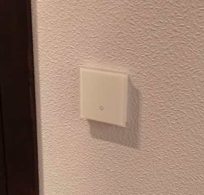
touch-sensitive, but they respond well to wet hands, turning on with a “hip”, with an elbow in clothes, etc.
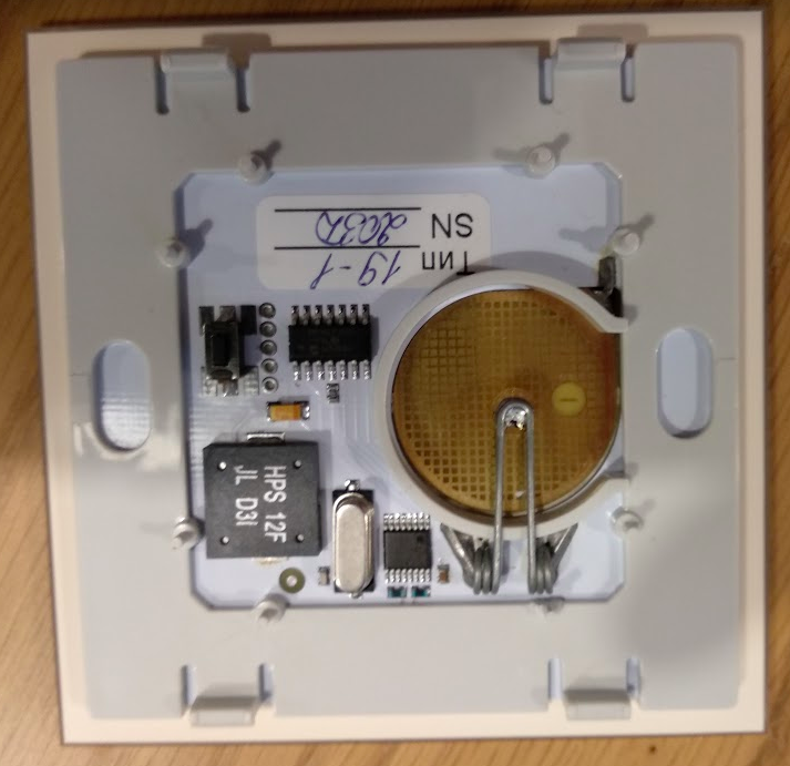
Included with the switch is to take a wireless relay, which costs about the same as the switch itself. But it was possible to go another way, especially since there was an ordinary radio module at 866 MHz.
Were made receivers that allow you to connect up to 7 radio buttons:
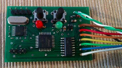
More precisely, radio buttons can be connected there more, but outputs from the board 7. The board's software allows you to control the button's output when receiving a signal in four ways: a) turn on the output, b) turn off the output, c) switch the current state, d) turn on the output and then turn off after a certain interval.
The radio button responds to a simple click and a long press. For a receiver card, it looks like different radio buttons.
Each radio button sends a packet of 6 bytes, the packet structure was not understood, but was used to identify the button entirely.
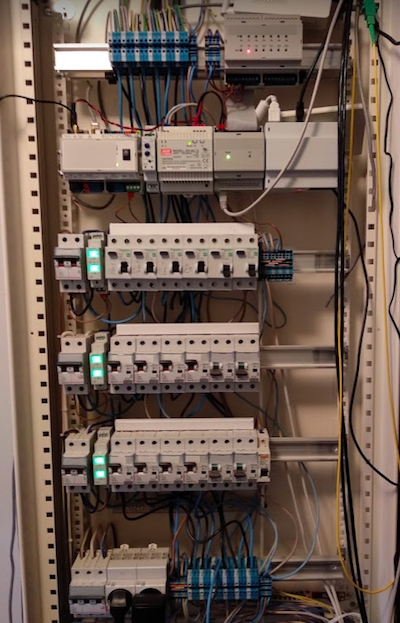
Initially, organization of electricians was assumed according to the star scheme, but considering the number of wires that had to be drawn in the wires, it was decided to change the schemes to the following: small electrical panels were installed in each room, two phases were connected to them from the main panel, and the wires to each outlet were already scattered around the room.
Here is one of the room panels:
This scheme allowed reducing the number of wires, and simplify installation.
Two twisted-pair wires were also connected to each room shield.
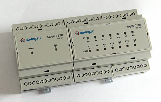
Each controller has a controller (megadevice from ab-log.ru) that is able to control the relay using HTTP commands. And a receiver for radio buttons is connected to this controller (which has 7 inputs):
Room flap without a lid (the arrow shows the receiver):

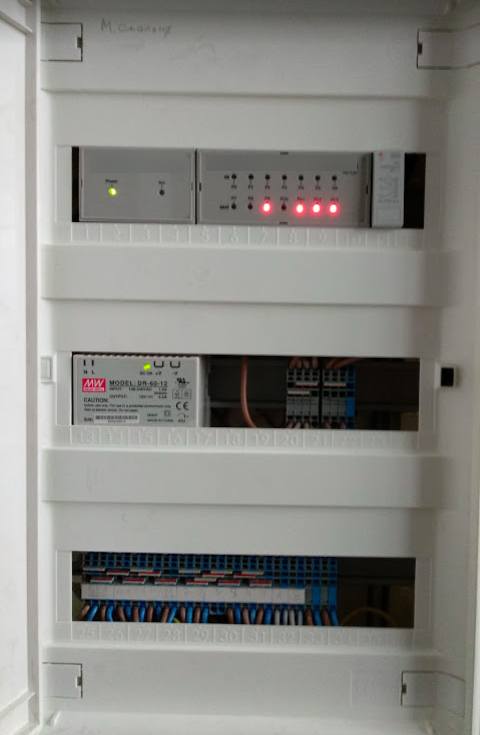
A server is installed in the main dashboard based on rapberrypi, to which all room controllers are connected.
Main
dashboard : Openhab2 with a module for room controllers is spinning on the server.
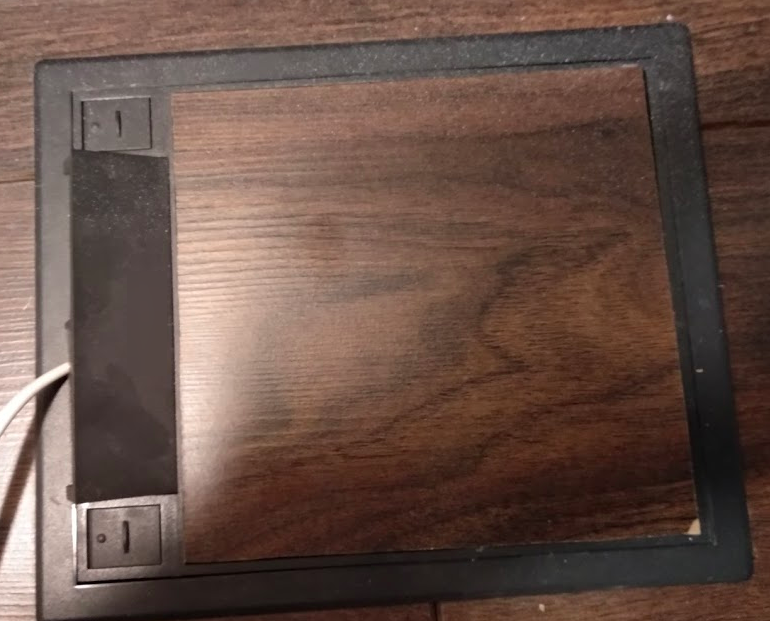
The rooms used hatches for 4-6 outlets.
Open hatch:

Closed hatch:
With the help of a room controller it is possible to switch each (almost) outlet in the hatch.Pants
color differentiation used
Ceiling lighting on the first floor (kitchen, pantry, c / a) diluted on the second floor through the ceiling, lighting in the c / y of the second floor, on the ceiling, made in the wall under the tile.
All other lighting is implemented in the form of floor lamps and table lamps.
In the kitchen, on the working surface of the table, the cat uses such retractable socket outlets:
Bottom
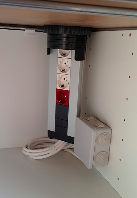
view: Top view:
In addition to the room shields, two main exhaust fans are installed in the main bathroom.
The Xiaomi MiHome controller is also connected to the server, for which there is support in openhab, which allows integrating a large number of wireless modules into the system: temperature / humidity sensors, window / door opening sensors, motion sensors, etc.
For example: a wireless temperature / humidity sensor is installed in the c / c. The following scenario is realized: the fan turns on 30 seconds after the light is turned on in the on / off and turns off 5 minutes after the light is turned off, but if the humidity is greater than the threshold, the fan will continue to work.
The result was a convenient system with which you can control every electrical device in your home using flexible openhab scripts using a large number of different devices that are supported by the openhab community.
When building a house, there was a question about how to organize an electrician correctly, provided that the walls are made of CIP panels, which cannot be tolled. There is an option to “wrap” a thick layer of drywall on the walls and stitch it, but this method did not seem very successful to me because I had to turn a rather drywall to a rather thick layer to remove the wire sleeve to the wall.
In the end, it was decided to remove everything that is possible under the raised floor. There went the heating pipes and metal boxes with wiring.
And it was decided not to touch the walls at all, place the sockets in the flaps, and use wireless switches.
That's what happened ...
To arrange the wiring, a galvanized box with a width of 200 mm and a height of 50 mm was used. with a lid. This box was laid out around the perimeter in each room.
To control the lighting were selected wireless switches, which had the widest choice of colors (design - our everything). And when the color of the walls was chosen, the switches were ordered. The switches are
touch-sensitive, but they respond well to wet hands, turning on with a “hip”, with an elbow in clothes, etc.
Included with the switch is to take a wireless relay, which costs about the same as the switch itself. But it was possible to go another way, especially since there was an ordinary radio module at 866 MHz.
Were made receivers that allow you to connect up to 7 radio buttons:
More precisely, radio buttons can be connected there more, but outputs from the board 7. The board's software allows you to control the button's output when receiving a signal in four ways: a) turn on the output, b) turn off the output, c) switch the current state, d) turn on the output and then turn off after a certain interval.
The radio button responds to a simple click and a long press. For a receiver card, it looks like different radio buttons.
Each radio button sends a packet of 6 bytes, the packet structure was not understood, but was used to identify the button entirely.
Initially, organization of electricians was assumed according to the star scheme, but considering the number of wires that had to be drawn in the wires, it was decided to change the schemes to the following: small electrical panels were installed in each room, two phases were connected to them from the main panel, and the wires to each outlet were already scattered around the room.
Here is one of the room panels:
This scheme allowed reducing the number of wires, and simplify installation.
Two twisted-pair wires were also connected to each room shield.
Each controller has a controller (megadevice from ab-log.ru) that is able to control the relay using HTTP commands. And a receiver for radio buttons is connected to this controller (which has 7 inputs):
Room flap without a lid (the arrow shows the receiver):
A server is installed in the main dashboard based on rapberrypi, to which all room controllers are connected.
Main
dashboard : Openhab2 with a module for room controllers is spinning on the server.
The rooms used hatches for 4-6 outlets.
Open hatch:
Closed hatch:
With the help of a room controller it is possible to switch each (almost) outlet in the hatch.
color differentiation used
Ceiling lighting on the first floor (kitchen, pantry, c / a) diluted on the second floor through the ceiling, lighting in the c / y of the second floor, on the ceiling, made in the wall under the tile.
All other lighting is implemented in the form of floor lamps and table lamps.
In the kitchen, on the working surface of the table, the cat uses such retractable socket outlets:
Bottom
view: Top view:
In addition to the room shields, two main exhaust fans are installed in the main bathroom.
The Xiaomi MiHome controller is also connected to the server, for which there is support in openhab, which allows integrating a large number of wireless modules into the system: temperature / humidity sensors, window / door opening sensors, motion sensors, etc.
For example: a wireless temperature / humidity sensor is installed in the c / c. The following scenario is realized: the fan turns on 30 seconds after the light is turned on in the on / off and turns off 5 minutes after the light is turned off, but if the humidity is greater than the threshold, the fan will continue to work.
The result was a convenient system with which you can control every electrical device in your home using flexible openhab scripts using a large number of different devices that are supported by the openhab community.