2D-> 3D in Augmented reality
In this article, I will tell you how to build 3D space in Augmented reality applications using the found location of an object in a scene. To do this, you need to get two matrices - projection (GL_PROJECTION) and model (GL_MODELVIEW) for work, for example, in OpenGL. We will do this using the OpenCV library .
Recently I had to solve this problem, but I did not find a resource where it was just explained in stages how to do it (maybe I was looking badly), but there are enough pitfalls in this problem. In any case, an article on the hub describing this task will not hurt.
Introduction
I myself am an iOS programmer, in my free time I am developing my own Augmented Reality engine. The base was taken by OpenCV - an open source library for computer vision.
In general, the most interesting proposal for mobile devices (iOS / Android) in this area are the development of Qualcomm.
More recently, they released their own AR SDK under the name Vuforia. At the same time, using the SDK is free both for development and for putting the application into the store (AppStore, AndroidMarket), as the Licensing paragraph proudly states. At the same time, they write that you should warn the end user that this SDK may collect some anonymous information and send it to Qualcomm servers. You can find this section by clicking on this link in the right menu Getting Started SDK -> Step 3: Compiling & Running ... -> Publish Your Application. And plus to this, you can consider me paranoid, but I'm 90% sure that when their SDK gains a certain percentage of popularity, they will say “That's it, the freebie is over, pay grandmas”.
Therefore, I think the development of my own engine is not a waste of time.
Actually, to the point!
Theory
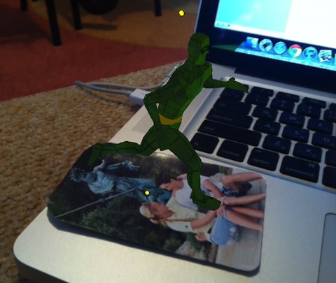
We believe that at this point you have implemented OpenCV in your project ( how? ), And have already written a method for recognizing an object in a frame coming from the camera. That is, you have approximately such a picture:

The theory on this issue can be found in many sources. I provided the main links below. The starting resource is the OpenCV documentation page , although there are many reading questions.
In a nutshell, to build 3D space from the found 2D homography, we need to know 2 matrices:
- Internal matrix (intrinsic matrix), or camera matrix - this matrix consists of camera parameters - focal distance along two axes ( fx , fy ) and focus center coordinate ( cx , cy ).
The structure of this matrix: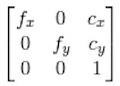
- An extrinsic matrix, or model matrix, is the model’s stretch, rotate, and transport matrix. It, in fact, uniquely sets the position of the object in space. The structure of:
 ,
,
where the diagonal elements are responsible for the tensile remaining elements r of rotation, and the elements t - for migration.
Note: in general, the structure of this matrix may vary depending on the model (coordinate transformation equations). For example, in the same OpenGL, a matrix of a slightly different structure is transmitted, but key elements are always present in it.
Practice
In practice, in order for OpenGL to render a 3D model on top of our object, we need to set it:
- The projection matrix is GL_PROJECTION.
- The model matrix is GL_MODELVIEW.
Note: In iOS, you can use 2 versions of OpenGLES - 1.1 and 2.0. The main difference is the presence of shaders in the second version. In both cases, we must specify 2 matrices, only in the first case they are defined by a construction of the type:
glMatrixMode(GL_PROJECTION);
glLoadMatrixf(projectionMatrix);
glMatrixMode(GL_MODELVIEW);
glLoadMatrixf(modelViewMatrix);
And in the second, you pass them to the input to the shaders.
Next, we will determine that the size of the frame that you get from the camera is cameraSize = (width, height). In my case, cameraSize = (640, 480).
Let's figure out how to build each matrix.
Projection matrix
This matrix is based on the camera matrix. As shown above, the latter consists of certain camera parameters. In theory, these parameters can be calculated based on the technical characteristics of the camera, but in practice no one does.
The process of finding camera parameters is called its calibration. OpenCV contains all the necessary functions for performing calibration. Also, there is an example that allows you to simply calibrate your webcam online. But we need to calibrate the camera on the device - iPhone / iPad / iPod. And here I went along the path described here .
We will calibrate the camera “offline”. This means that we will take pictures of the calibration template (checkerboard) with the camera of our device, transfer the photos to the computer, and calculate the parameters from these photos. A few points:
- Print a checkerboard template onto an A4 sheet. The sheet should be clean, it is very desirable that the printer does not "flow".
- Try to ensure that in the pictures the sheet of the chessboard lay exactly on the surface - the edges were not bent, any bends of the sheet were absent. To do this, you can stick it to the cardboard, or just put heavy objects on the edges, but so that they do not block the look of the template.
- Pictures from the camera must be converted to the size of cameraSize. This is not an obvious step - for example, on iPhone 4, I use the 640x480 camera frame size for recognition, and when you take a simple camera picture and drop it onto a computer, you get larger pictures (2592x1936), I compressed them to 640x480, and I used these in the program.
- The number of shots of the template should be 12-16 + taken from different angles. Personally, I used 16 shots, while changing the parameters built on 12 and 16, although not large, is present. In general, the more images, the more accurate the parameters, and this accuracy will further affect the presence / absence of shifts when building 3D objects.
- In addition to the camera matrix, at this stage we find distortion coefficients. In a nutshell, these coefficients describe the distortion of the image by the camera lens. You can read more in the OpenCV documentation and on Wikipedia . As for mobile devices, most cameras have high quality cameras, and these ratios are relatively small, so you can ignore them.
Xcode project calibration program you can download here . In this case, you must have compiled OpenCV. Or you can download the compiled framework from here .
The photos themselves, you need to put in the folder with the compiled binary, and rename in order.
If everything is ok, you will get 2 files in the program output:
- Intrinsics.xml - here the 3x3 camera matrix will be recorded line by line
- Distortion.xml - there will be calculated coefficients.
If the template is not found in some images, try replacing these images with others with better lighting, possibly at a less acute angle to the template. OpenCV should easily find all the internal points of the template.
Having numbers from these files, we can build a projection matrix for OpenGL.
float cameraMatrix[9] = {6.24860291e+02, 0., cameraSize.width*0.5f, 0., 6.24860291e+02, cameraSize.height*0.5f, 0., 0., 1.};
- (void)buildProjectionMatrix {
    // Camera parametersdouble f_x = cameraMatrix[0]; // Focal length in x axisdouble f_y = cameraMatrix[4]; // Focal length in y axis (usually the same?)double c_x = cameraMatrix[2]; // Camera primary point xdouble c_y = cameraMatrix[5]; // Camera primary point ydouble screen_width = cameraSize.width; // In pixelsdouble screen_height = cameraSize.height; // In pixelsdouble near = 0.1;  // Near clipping distancedouble far = 1000;  // Far clipping distance
    projectionMatrix[0] = 2.0 * f_x / screen_width;
	projectionMatrix[1] = 0.0;
	projectionMatrix[2] = 0.0;
	projectionMatrix[3] = 0.0;
	projectionMatrix[4] = 0.0;
	projectionMatrix[5] = 2.0 * f_y / screen_height;
	projectionMatrix[6] = 0.0;
	projectionMatrix[7] = 0.0;
	projectionMatrix[8] = 2.0 * c_x / screen_width - 1.0;
	projectionMatrix[9] = 2.0 * c_y / screen_height - 1.0;
	projectionMatrix[10] = -( far+near ) / ( far - near );
	projectionMatrix[11] = -1.0;
	projectionMatrix[12] = 0.0;
	projectionMatrix[13] = 0.0;
	projectionMatrix[14] = -2.0 * far * near / ( far - near );
	projectionMatrix[15] = 0.0;
}
A few notes:
- We replace the coefficients ( cx , cy ) of the camera matrix with the center of our frame. Then there will be no displacement of the 3D model relative to the object in the frame. The author of the post came to the same conclusion (see UPDATE: at the end of the article).
- I took the formulas for obtaining the projection matrix from here . In fact, in this way a perspective projection is set, which takes into account the parameters of our camera and the frame size.
- The presented matrix of the camera was obtained by me for iPhone 4. For other devices, the matrix will be different, although, I think, not much.
Matrix model
When building this matrix, this question in StackOverflow helped me .
Fortunately, in OpenCV the necessary functions are already implemented.
So the code:
float cameraMatrix[9] = {6.24860291e+02, 0., cameraSize.width*0.5f, 0., 6.24860291e+02, cameraSize.height*0.5f, 0., 0., 1.};
float distCoeff[5] = {1.61426172e-01, -5.95113218e-01, 7.10574386e-04, -1.91498715e-02, 1.66041708e+00};
- (void)buildModelViewMatrixUseOld:(BOOL)useOld {
    clock_t timer;
    startTimer(&timer);
    CvMat cvCameraMatrix = cvMat( 3, 3, CV_32FC1, (void*)cameraMatrix );
	  CvMat cvDistortionMatrix = cvMat( 1, 5, CV_32FC1, (void*)distCoeff );
    CvMat* objectPoints = cvCreateMat( 4, 3, CV_32FC1 );
    CvMat* imagePoints = cvCreateMat( 4, 2, CV_32FC1 );
//  Defining object points and image pointsint minDimension = MIN(detector->modelWidth, detector->modelHeight)*0.5f;
    for (int i=0; i<4; i++) {
        float objectX = (detector->x_corner[i] - detector->modelWidth/2.0f)/minDimension;
        float objectY = (detector->y_corner[i] - detector->modelHeight/2.0f)/minDimension;
        cvmSet(objectPoints, i, 0, objectX);
        cvmSet(objectPoints, i, 1, objectY);
        cvmSet(objectPoints, i, 2, 0.0f);
        cvmSet(imagePoints, i, 0, detector->detected_x_corner[i]);
        cvmSet(imagePoints, i, 1, detector->detected_y_corner[i]);
    }
    CvMat* rvec = cvCreateMat(1, 3, CV_32FC1);
    CvMat* tvec = cvCreateMat(1, 3, CV_32FC1);
    CvMat* rotMat = cvCreateMat(3, 3, CV_32FC1);
    cvFindExtrinsicCameraParams2(objectPoints, imagePoints, &cvCameraMatrix, &cvDistortionMatrix,
                                 rvec, tvec);
//    Convert it
    CV_MAT_ELEM(*rvec, float, 0, 1) *= -1.0;
    CV_MAT_ELEM(*rvec, float, 0, 2) *= -1.0;
    cvRodrigues2(rvec, rotMat);
    GLfloat RTMat[16] = {cvmGet(rotMat, 0, 0), cvmGet(rotMat, 1, 0), cvmGet(rotMat, 2, 0), 0.0f,
                        cvmGet(rotMat, 0, 1), cvmGet(rotMat, 1, 1), cvmGet(rotMat, 2, 1), 0.0f,
                        cvmGet(rotMat, 0, 2), cvmGet(rotMat, 1, 2), cvmGet(rotMat, 2, 2), 0.0f,
                        cvmGet(tvec, 0, 0)  , -cvmGet(tvec, 0, 1), -cvmGet(tvec, 0, 2),    1.0f};
    cvReleaseMat(&objectPoints);
    cvReleaseMat(&imagePoints);
    cvReleaseMat(&rvec);
    cvReleaseMat(&tvec);
    cvReleaseMat(&rotMat);
    printTimerWithPrefix((char*)"ModelView matrix computation", timer);
}
First we need to define 4 pairs of points of the object and the corresponding position in the frame.
The position points in the frame are the vertices of the quadrangle that describes the (bounding) object in the frame. To obtain these points, having the homography of the transformation H, you can simply act on the extreme points of the template with this homography:

There are a couple of points regarding the points of the object itself:
- The points of the object are set in 3D, and the points on the frame in 2D. Accordingly, if we assume that we give them a non-zero value of z , then the origin on z will be shifted relative to the plane of the object in the frame. It is easier to understand from the data of two pictures:
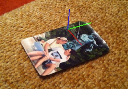
z = 1.0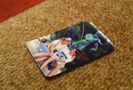
z = 0.0 - Also, we set the points of the object so that it is more convenient for us to work in this 3D space. For example, I want the origin to be right in the center of the template, and the unit of length is half the smaller side (in the minDimension code). In this case, we will not depend on the specific size of the template in pixels, and 3D space will be scaled on the smaller side.
The constructed matrices are passed to the cvFindExtrinsicCameraParams2 function . She will build us a rotation vector, and a transfer vector. From the rotation vector we need to get the rotation matrix. This is done using the cvRodrigues2 function , after transforming the rotation vector a little by multiplying the second and third elements by -1 . Further, all that remains for us is to save the obtained data in a model matrix for OpenGL. In this case, the OpenGL matrix must be transposed.
That's all, we delete temporary objects, and the matrix of the model is obtained.
Total
Having a procedure for constructing two matrices, we can safely create a GLView, and draw models there. I note that the function of finding the matrix of the model is performed no more than 10 milliseconds on the iPhone 4, that is, its use will not lower the FPS of your recognition significantly.
Thanks for attention.
Learn more:
1.http : //old.uvr.gist.ac.kr/wlee/web/techReports/ar/Camera%20Models.html 2.http
: //www.hitl.washington.edu/artoolkit/mail-archive/message -thread-00653-Re - Questions-concering-.html
3. http://sightations.wordpress.com/2010/08/03/simulating-calibrated-cameras-in-opengl/
4. http: // www. songho.ca/opengl/gl_projectionmatrix.html