Simple soldering station on the microcontroller
A soldering iron is the main tool of those who are somehow connected with electronics. But most ordinary soldering irons are only suitable for soldering pots, a more or less normal soldering iron with a thermostat and interchangeable tips is expensive, and there is nothing to say about soldering stations. I propose to assemble a simple soldering station that does not differ in functionality from the serial ones.

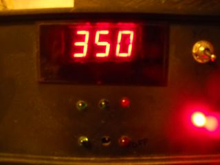
The microcontroller works like a thermostat: receives data from a thermal converter and controls a transistor, which in turn turns on the heater. The set and current temperature of the soldering iron are displayed on a seven-segment indicator. The buttons S1-S4 are used to set the temperature in increments of 100 ° С and 10 ° С, S5-S6 - to turn the station on and off (standby), S7 - switches the temperature display mode: current temperature or set (in this mode, you can change it ) Heater operation is indicated by LED1. In the event of a power outage, the last set temperature is stored in the non-volatile EEPROM memory and upon subsequent power-up, the station starts heating to this temperature.
The station used a network transformer for 18V 40W, any diode bridge capable of withstanding a current of 2A and a reverse voltage of 30V, for example, KTs410. The integral voltage stabilizer 7805 must be screwed to a radiator the size of at least a matchbox. Filter capacitors C1 - electrolytic at 100-500uF, C2, if desired, can be removed. Indicator - any for three digits with a dynamic indication and a common anode, it is better to hide it behind a light filter. Current limiting resistors R8-R11 with a resistance of 330Ω-1kΩ. Buttons S1-S6 without fixing, preferably clock buttons, S7 - toggle switch or button, but with fixing. Resistors R1-R7 - any, with a resistance of 10kOhm-100kOhm. Transistor T1 - N-channel MOSFET, controlled by a logic level, a permissible drain-source voltage of at least 25V and a current of at least 3A, for example: IRL3103, IRL3713, IRF3708, IRF3709 and others. The ATmega8 microcontroller with any suffix and case (pin numbering for the DIP case is shown in the diagram). Of the fuses, we only change CKSEL: we configure CKSEL3 ... 0 = 0100 to the internal 8 MHz oscillator, we don’t touch the rest. Such a scheme does not require any configuration and works immediately (if it is correctly assembled).
The scheme provides for the use of soldering irons used in commercially available soldering stations, for example Lukey or AOYUE. Such soldering irons are sold as spare parts and cost slightly more than the previously mentioned pan soldering irons. The main difference that concerns us is the type of temperature sensor, it can be a thermistor or a thermocouple. We need the first one. This type of converter is suitable for soldering irons inside of which there is a ceramic heating element HAKKO 003 (HAKKO A1321). An example of such a soldering iron is used in Lukey 868, 852D +, 936 and other soldering stations. Such a soldering iron is more expensive, but is considered to be of better quality.
Lukey soldering irons have a PS / 2 connector for connecting the station, while AOYUE - it looks like an old Soviet connector for connecting a tape recorder. On the Internet you can find their pinout, or you can just cut the connector and solder directly to the board. To find out where which wire is, you can measure the resistance: the heater will have about 3 ohms, and the thermistor will have about 50 ohms (at room temperature).
Almost all modern soldering irons for soldering stations have the ability to ground the tip, use it to protect soldered parts from static discharges.
All was soldered with EPSN with copper wire wound around the sting. I didn’t think about miniaturization.

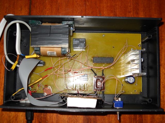
The insides were photographed two years ago, when it was just made, so attentive readers can notice the relay (replaced by a transistor) and a converter for a thermocouple (red resistors and a trimmer in the lower left corner).
The archive firmware and circuit in high resolution
Scheme
The microcontroller works like a thermostat: receives data from a thermal converter and controls a transistor, which in turn turns on the heater. The set and current temperature of the soldering iron are displayed on a seven-segment indicator. The buttons S1-S4 are used to set the temperature in increments of 100 ° С and 10 ° С, S5-S6 - to turn the station on and off (standby), S7 - switches the temperature display mode: current temperature or set (in this mode, you can change it ) Heater operation is indicated by LED1. In the event of a power outage, the last set temperature is stored in the non-volatile EEPROM memory and upon subsequent power-up, the station starts heating to this temperature.
Details
The station used a network transformer for 18V 40W, any diode bridge capable of withstanding a current of 2A and a reverse voltage of 30V, for example, KTs410. The integral voltage stabilizer 7805 must be screwed to a radiator the size of at least a matchbox. Filter capacitors C1 - electrolytic at 100-500uF, C2, if desired, can be removed. Indicator - any for three digits with a dynamic indication and a common anode, it is better to hide it behind a light filter. Current limiting resistors R8-R11 with a resistance of 330Ω-1kΩ. Buttons S1-S6 without fixing, preferably clock buttons, S7 - toggle switch or button, but with fixing. Resistors R1-R7 - any, with a resistance of 10kOhm-100kOhm. Transistor T1 - N-channel MOSFET, controlled by a logic level, a permissible drain-source voltage of at least 25V and a current of at least 3A, for example: IRL3103, IRL3713, IRF3708, IRF3709 and others. The ATmega8 microcontroller with any suffix and case (pin numbering for the DIP case is shown in the diagram). Of the fuses, we only change CKSEL: we configure CKSEL3 ... 0 = 0100 to the internal 8 MHz oscillator, we don’t touch the rest. Such a scheme does not require any configuration and works immediately (if it is correctly assembled).
Soldering iron
The scheme provides for the use of soldering irons used in commercially available soldering stations, for example Lukey or AOYUE. Such soldering irons are sold as spare parts and cost slightly more than the previously mentioned pan soldering irons. The main difference that concerns us is the type of temperature sensor, it can be a thermistor or a thermocouple. We need the first one. This type of converter is suitable for soldering irons inside of which there is a ceramic heating element HAKKO 003 (HAKKO A1321). An example of such a soldering iron is used in Lukey 868, 852D +, 936 and other soldering stations. Such a soldering iron is more expensive, but is considered to be of better quality.
Finally
Lukey soldering irons have a PS / 2 connector for connecting the station, while AOYUE - it looks like an old Soviet connector for connecting a tape recorder. On the Internet you can find their pinout, or you can just cut the connector and solder directly to the board. To find out where which wire is, you can measure the resistance: the heater will have about 3 ohms, and the thermistor will have about 50 ohms (at room temperature).
Almost all modern soldering irons for soldering stations have the ability to ground the tip, use it to protect soldered parts from static discharges.
But what happened
All was soldered with EPSN with copper wire wound around the sting. I didn’t think about miniaturization.
The insides were photographed two years ago, when it was just made, so attentive readers can notice the relay (replaced by a transistor) and a converter for a thermocouple (red resistors and a trimmer in the lower left corner).
The archive firmware and circuit in high resolution