DIY autonomous drone controlled via the Internet. Part 2 about software
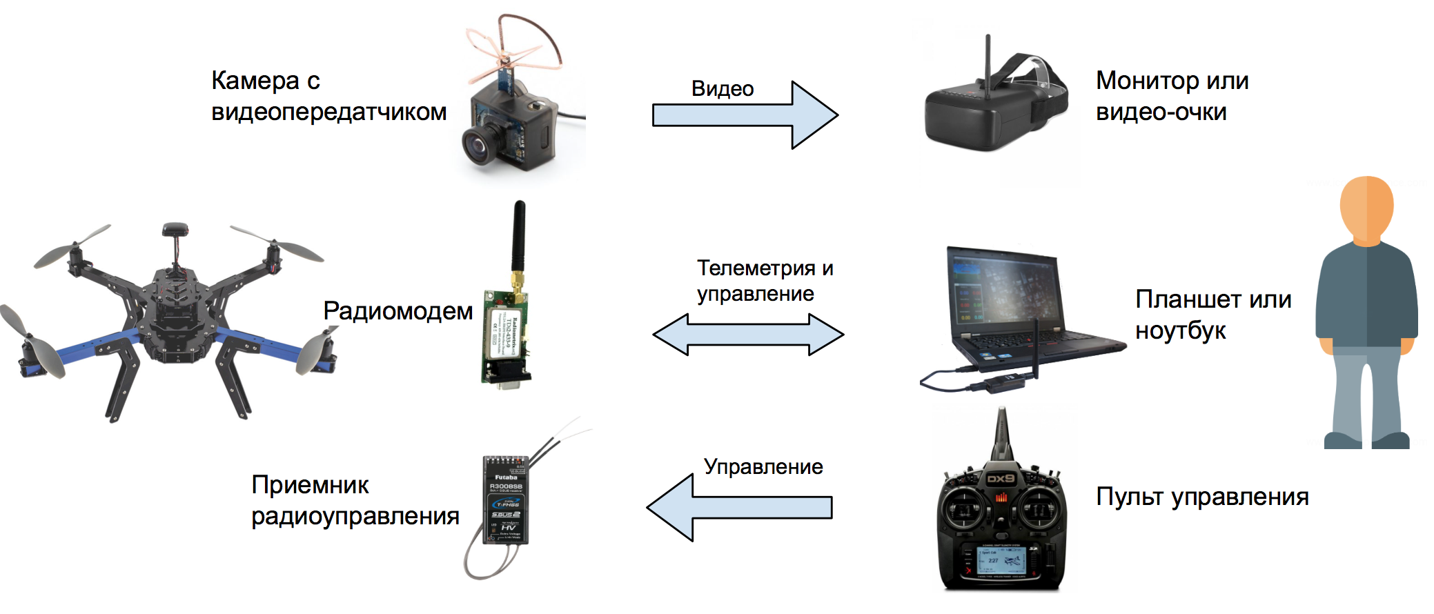
This is a continuation of the story of an autonomous drone. In the first part it was told about hardware, in it it will be a question about software. For a start, a small educational program about the interaction of the operator with the copter. Here is a typical scheme for the majority of self-assembled drones:
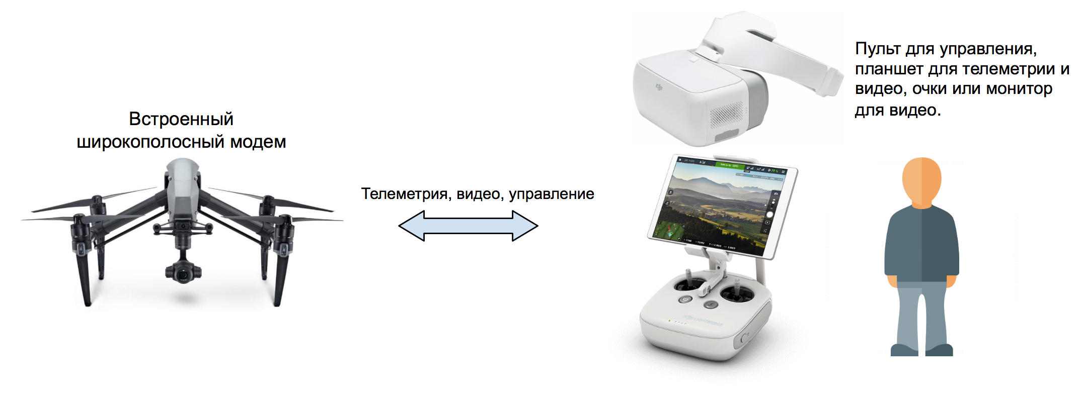
But the scheme for advanced drones:
This is how toy drones work that are controlled from a smartphone:

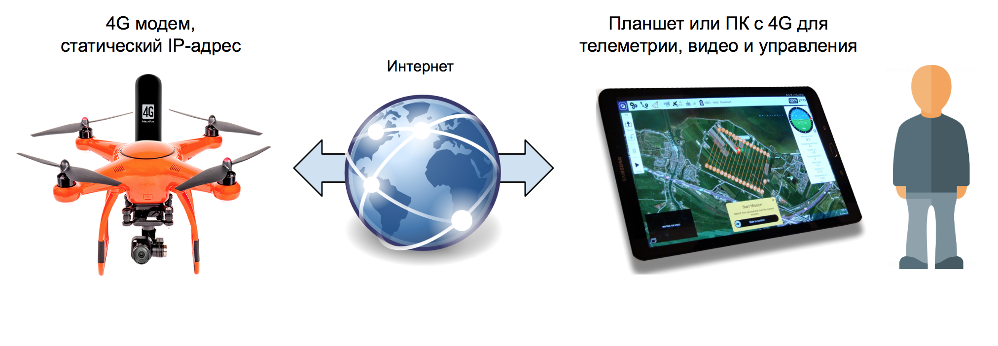
You can control the drone via the Internet as follows (if you have a SIM card with a static IP address):
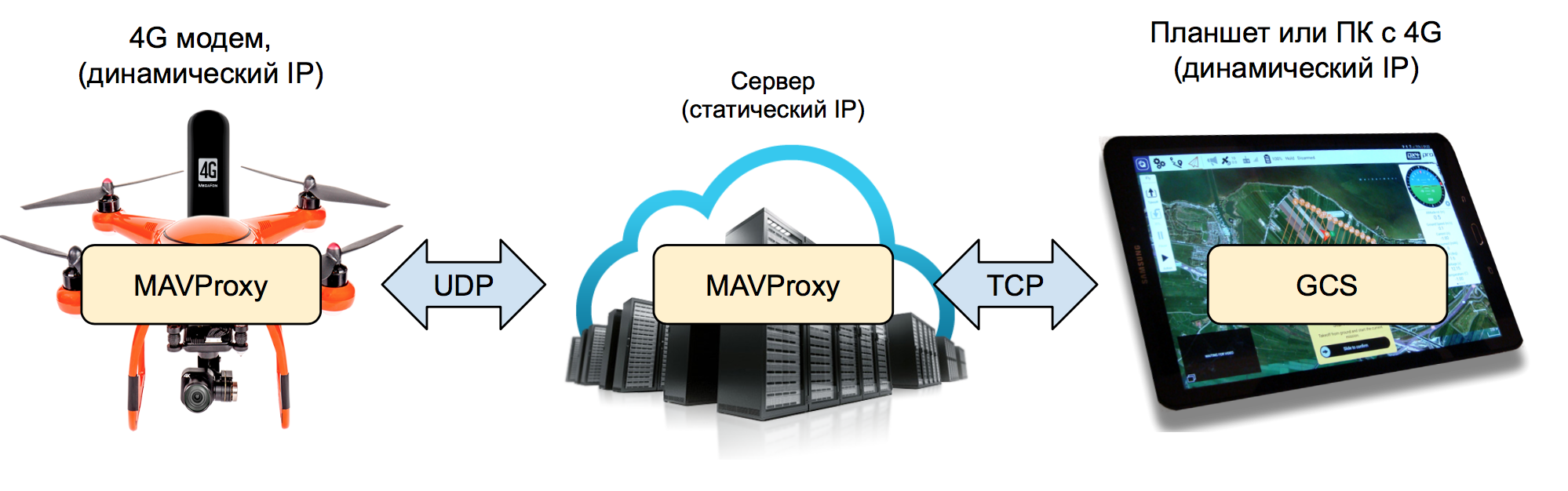
Or so, if the IP address is dynamic:
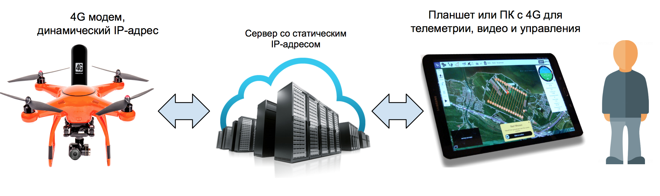
For reliability and redundancy of communication channels, the last option can be developed to state:

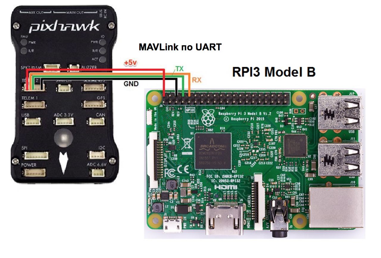
Next, I will describe the flight controller configuration process Emlid Navio 2 and microcomputer Raspberry Pi 3.

However, with minor modifications, these settings are suitable for any flight controller, which can communicate via the protocol MAVLink in conjunction with any Comp Intermediate location on the Linux operating system family.
Important! Adjustment must be done with the power off on the speed controllers so that the engines do not accidentally start.
To control the UAV uses special programs GCS (Ground Control Station). Further in the text I will use this abbreviation. I liked QGroundControl , a multi-platform (Windows, Linux, MacOS, iOS, Android) open source GCS, which became part of the DroneCode project . But there are alternatives, free and commercial: APM Planner , MissionPlanner , UgCS , LibrePilot , OpenPilot , Tower (DroidPlanner) for Android, MAVPilot (iOS), SidePilot (iOS). And also console MAVProxy .
For normal autopilot operation, it is highly recommended to use “fast” SD cards (class 10). Slow memory cards do not have time to save the autopilot logs even at a small frequency, as a result of which they turn out to be curves or not written at all. Evidence of this may be the error “ No IO heartbeat ”, which can be observed in the MAVLink console (how to watch the MAVLink console is described below). When buying, look at the opportunity to write 4K video: most likely it will be a fast SD. Unfortunately, I learned about it after the fall of the drone, when it was necessary to analyze the logs and find out the reason. Logs were unreadable for several GCS. The reason for turning off the motors in flight turned out to be trivial: I forgot to correct in the settings the value of the minimum voltage on the battery to failsafe.
So, download the finished image of the Raspbian Stretch with the pre-installed Ardupilot and ROS from Emlid from the page of the original manual . And write it to the memory card using Etcher or any similar program.
To immediately connect Raspberry to your WiFi network, you need to edit the wpa_supplicant.conf file in the root of the SD card. It should contain the following lines:
You can configure it without WiFi by connecting the single card to the router with an Ethernet cable. Now remove the SD card from the PC, insert it into the Raspberry and turn on the power. After half a minute, it should appear in the admin panel of the router on the connected devices page (navio hostname ).
Open the SSH client and connect to Raspberry (the local IP address is navio instead of RASPBERRY_IP_ADDRESS ):
Standard password: raspberry . First of all, you need to expand the OS file system to the entire volume of the SD card:
and reboot:
After a reboot, connect again and update the distribution:
Install additional packages:
and compile the gst-rpicamsrc wrapper for gstreamer and the native Raspicam camera:
Check if the camera is working (video file test.h264 is being created):
If gstreamer starts, wait a couple of seconds for the video to be recorded. Abort process can keys Ctrl + C . If there is video, then the camera is working.
Releases of new versions of the Ardupilot are a bit late in the build from Emlid. If the necessary functionality is available in the latest version, then you can install it from source by following this instruction .
The developers of Navio have added a simple and convenient Emlid tool to their sensors for checking sensors and configuring the Ardupilot. First, check if the Raspberry Navio Controller sees:
If, in response to this command, it gives something like:
means sees. Check the status of the sensors (show the list and status):
and PWM controller drivers in the Linux kernel:
0 = not working, 1 = working.
The PWM controller firmware is updated as follows:
Now configure the Ardupilot:
A text-based GUI with step-by-step menus will open in the terminal. Select the latest version of the copter, the type of arducopter , autorun on power-up ( On boot: enable ), start after setting ( Ardupilot: start ).

We leave through the menu item Quit .
Check if Ardupilot is running:
Note that the startup file in systemd is called arducopter , since the copter option was configured .
Now you need to configure the Ardupilot so that it sends us telemetry. To do this, edit the configuration file:
It should contain the following lines:
Save the file ( Ctrl + X , then Y ) and restart the Ardupilot:
You can check the status of the Ardupilot process with the following command:
With these settings, the Ardupilot will broadcast the telemetry ( MAVLink packets ) to the local UDP port 14550. Next, the MAVProxy script (description below) will pick up the telemetry from there and send it to the GCS or the script, and send packets with commands in the opposite direction.
Instead of the local address and port, you can record the IP address of the PC or tablet on the local network and the packets will be broadcast right there.

However, this approach is justified if the telemetry data is not used anywhere else and the device with a GCS has a static IP address. Otherwise, each time in the settings of the Ardupilot will have to register a new one. In order to communicate with the autopilot via TCP, several GCS with dynamic addresses and some other scripts on the on-board computer could be used at the same time, it is more convenient to use MAVProxy.
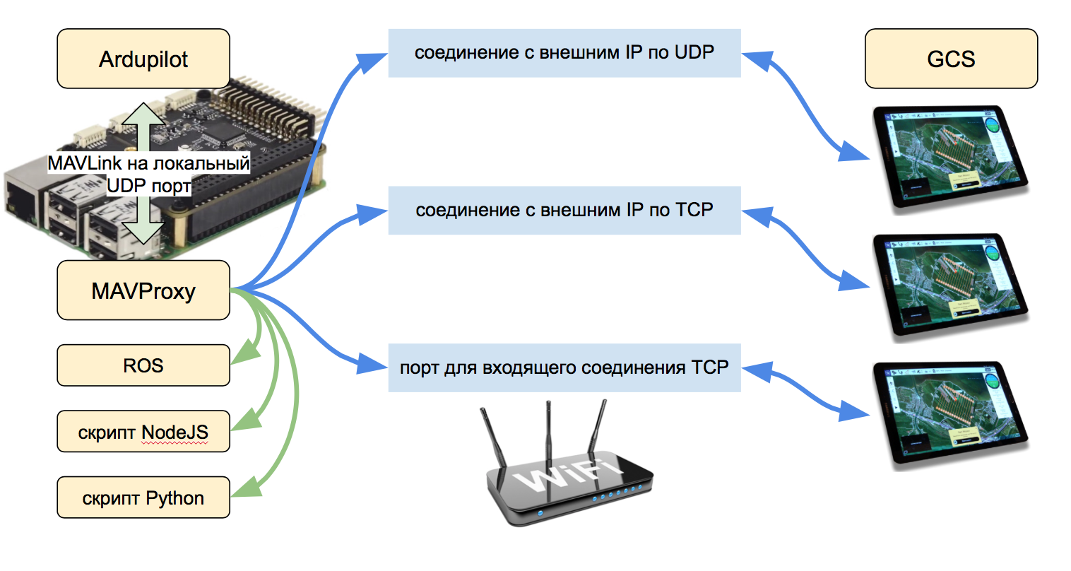
This script (written in Python) can receive MAVLink packets to the local UDP address and relay them to several local or remote IP addresses both via UDP and TCP. Packets are sent in both directions to the Ardupilot ⇔ GCS. In addition, MAVProxy is a complete GCS, but with a text interface.
MAVProxy is already installed in the Navio image. It can also be installed on a PC (Windows, Linux, MacOS) for further communication with the autopilot in console mode.
Making sure that the Ardupilot is working, run the MAVProxy script with the following command on Raspberry:
The parameter --master = udp: 127.0.0.1: 14550 specifies the data source for the script. This is a local UDP port that has been registered in the Ardupilot configuration file. After running the command, MAVProxy connects to this port and displays autopilot messages, just like mine:
Since the autopilot is not yet calibrated and is not fully tuned, messages also eloquently speak of this. In this mode, you can communicate with the autopilot through commands. If the drone were fully configured, then such a sequence of two teams would lead to the start of the engines and the take-off of the drone to a height of 20 m:
An uncalibrated autopilot will not fly, but will show messages with reasons why he cannot do this.
Stop the script ( Ctrl + C ) and run it again like this:
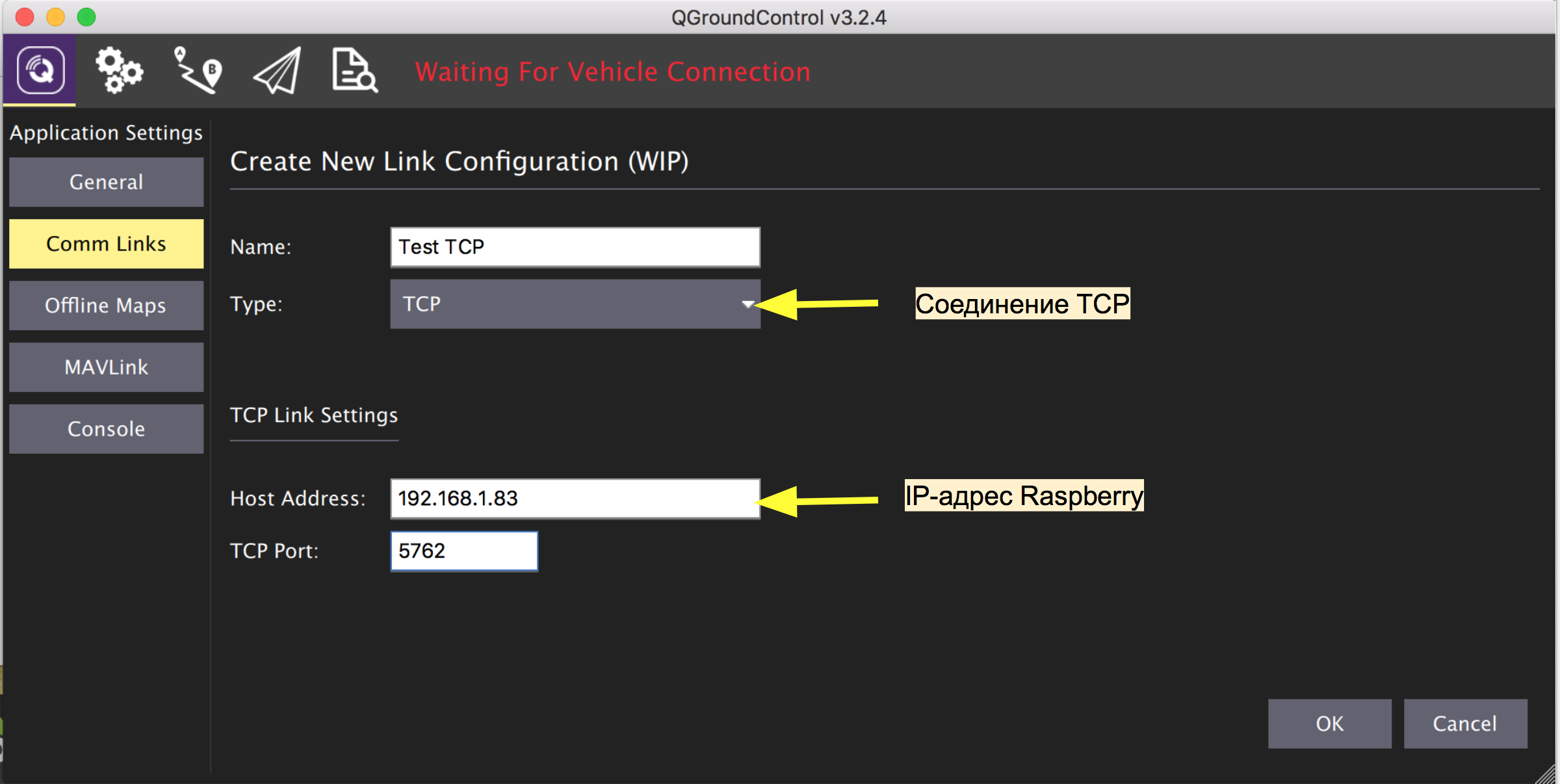
With the additional parameter --out = tcpin: 0.0.0.0: 5762 MAVProxy will listen to port 5762 on incoming TCP connections from GCS. Once the GCS connects, the data packets will start moving between the drone and the GCS. Let's try to connect from a PC:
If the connection is successful, then GCS will show a bunch of messages with the requirement to calibrate the sensors and load the onboard parameters with their current values:


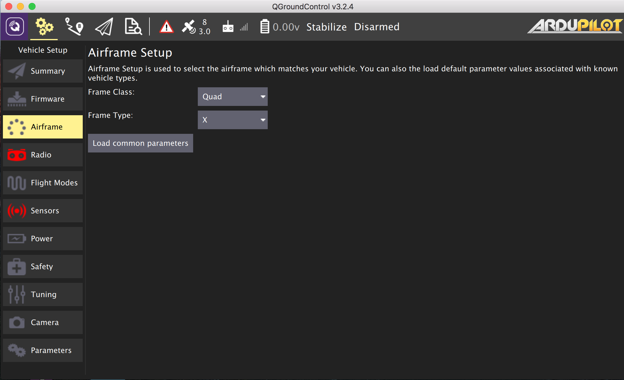
Autopilot calibration can be done in almost any GCS. The documentation Ardupilot she described in detail. First of all, we set the frame type. I have a standard 4-motor layout, so it's Quad the X .
The first flight is still better done in manual mode. We connect and calibrate the radio control (receiver and transmitter).

It remains to calibrate the accelerometer and compass.

In order for the Ardupilot to see and take into account data from external sensors, set the necessary parameters:
For PX4Flow ( sensor calibration and firmware update ) For laser altimeter VL53L0X ( instruction ) For IRLock
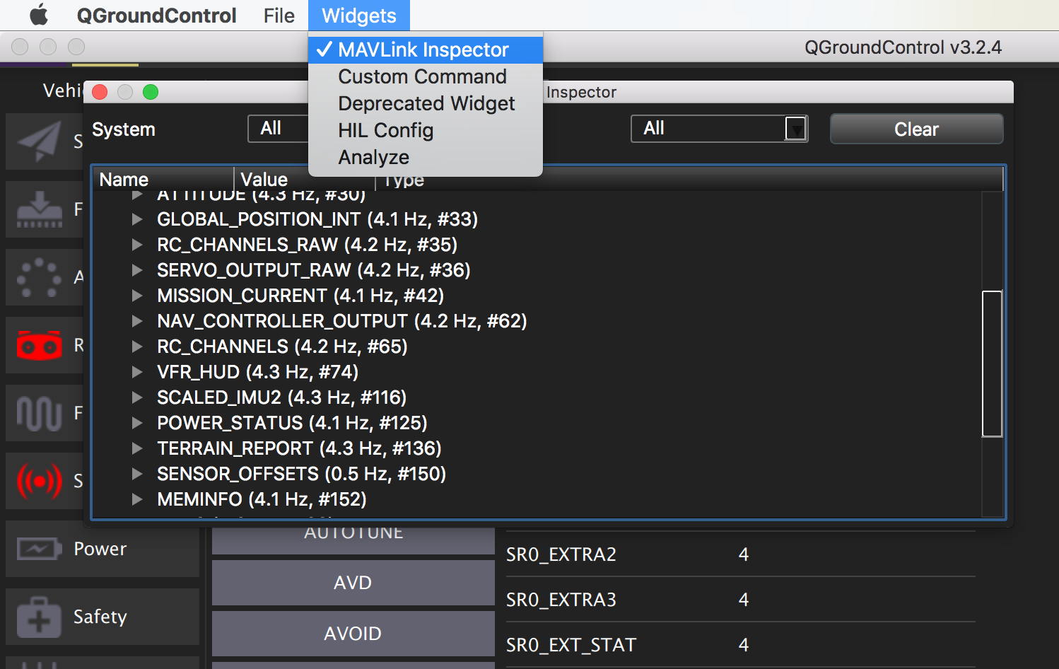
( detailed instructions , wiki IR-Lock ) For front-view sonar ( instruction ) A complete list of Ardupilot parameters . Now we restart the Ardupilot from the GCS menu, reconnect to the board and open the MAVLink Inspector window to see the data from the sensors. Unfortunately, the IR-Lock readings are not visible here, to analyze its work, you will have to look at the side logs. How to do this is described here . It remains to adjust the security settings and you can launch the drone: How to set up the gimbal and control of the main camera in detail I will write in one of the following articles, the main points are outlined here .

Let's check how the video broadcast on the WiFi network works. With this command, you can run video on the TCP port on Raspberry using the native raspivid utility for the Raspicam camera:
But this command does the same thing, only using the previously compiled rpi-camsrc wrapper for gstreamer:
In both cases, the h264 broadcast is available on the Raspberry IP address on port 5001.
You can view it by running such a command on your PC ( gstreamer must be installed ), instead of RPI_ADDRESS, specify the Raspberry address on the network:
As a result, a window with a video should open.
Almost any GCS has a built-in video player that can display an RTSP video stream. To make Raspberry RTSP server you can use VLC console player . Installation:
Video broadcast runs like this:
The video is available at (instead of RPI_ADDRESS , Raspberry address):
Setting up GCS: You


can use the stream address to connect several players on different devices, but since video capture and translation for Raspberry is a very laborious process, it’s better to use an external server for several video consumers ( description below).
In order for GCS to connect via the Internet to a drone with a dynamic IP address, an intermediate server with a static IP is needed on which the MAVProxy script will be launched. For these purposes, I used to rent a cloud server from one of the well-known providers. For MAVProxy, the most minimal configuration will do, but since I have the same server to do video retransmission, I chose the option with a little more memory (one core and 1 GB of memory, Ubuntu 18.04). For a minimum delay in the passage of data between the board and the GCS, the server should be located in the maximum geographical proximity to the drone and the GCS.
Install MAVProxy on the server. First, dependencies:
and then the script itself via PIP:
write the path:
and run the script with the following parameters:
MAVProxy listens on port 15001 for incoming telemetry packets from the drone via the UDP protocol, and port 15002 for an incoming TCP connection from GCS.
Run MAVProxy on Raspberry with one more parameter so that telemetry is also transmitted to the server (instead of SERVER_IP address of your server):
After starting the script on the onboard computer, messages from the autopilot will appear in the server console. As mentioned above, MAVProxy is a full-fledged GCS with a text interface and in this state you can already edit the parameters and control the drone via commands in the server console.
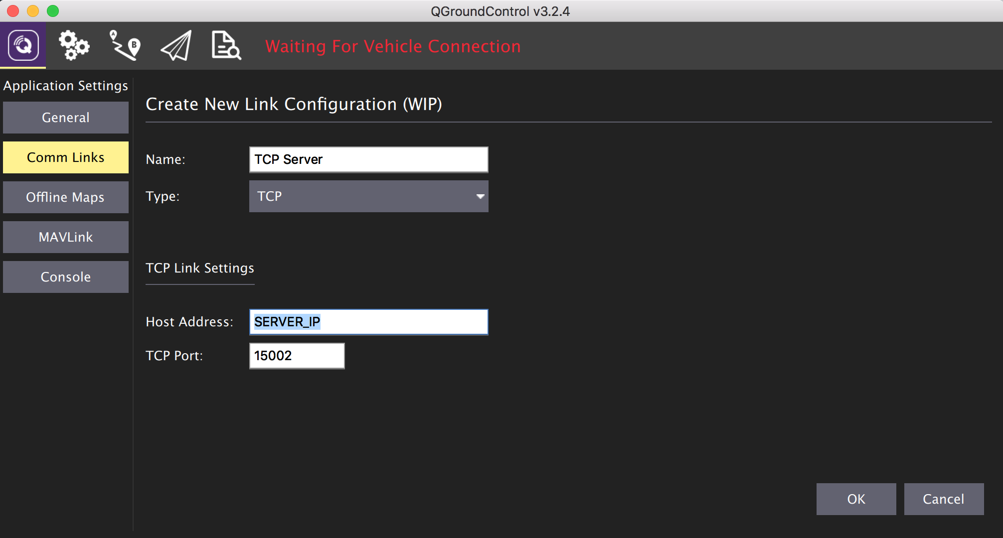
Connect GCS on a PC or tablet to the server. The connection settings are the same as for the local network, but instead of the Raspberry IP address, we specify the server address and port 15002.
Now you can connect a 4G USB modem to the Raspberry and estimate how long the artificial horizon on the screen reacts to.

For video retransmission, install the VLC player on the server:
After installation, run it as a relay with UDP port 5001 on the RTSP channel SERVER_IP: 8554 / live :
Onboard, launch video broadcasting from camera to server via UDP (instead of SERVER_IP server address):
The stream address can now be used as a video source in the GCS settings or opened in any player that supports this protocol.
Now you can plan a flight route and launch the drone via the Internet, after turning it on, for example, with the help of a telephone assistant.
Obviously, due to the relatively large travel time of video and telemetry over the network, this method is hardly suitable for FPV flights in manual mode between obstacles.
Topics for future publications:
To be continued…
But the scheme for advanced drones:
This is how toy drones work that are controlled from a smartphone:
You can control the drone via the Internet as follows (if you have a SIM card with a static IP address):
Or so, if the IP address is dynamic:
For reliability and redundancy of communication channels, the last option can be developed to state:
Next, I will describe the flight controller configuration process Emlid Navio 2 and microcomputer Raspberry Pi 3.
However, with minor modifications, these settings are suitable for any flight controller, which can communicate via the protocol MAVLink in conjunction with any Comp Intermediate location on the Linux operating system family.
Important! Adjustment must be done with the power off on the speed controllers so that the engines do not accidentally start.
Drone management software on PCs and tablets
To control the UAV uses special programs GCS (Ground Control Station). Further in the text I will use this abbreviation. I liked QGroundControl , a multi-platform (Windows, Linux, MacOS, iOS, Android) open source GCS, which became part of the DroneCode project . But there are alternatives, free and commercial: APM Planner , MissionPlanner , UgCS , LibrePilot , OpenPilot , Tower (DroidPlanner) for Android, MAVPilot (iOS), SidePilot (iOS). And also console MAVProxy .
Installing the OS image on the SD card
For normal autopilot operation, it is highly recommended to use “fast” SD cards (class 10). Slow memory cards do not have time to save the autopilot logs even at a small frequency, as a result of which they turn out to be curves or not written at all. Evidence of this may be the error “ No IO heartbeat ”, which can be observed in the MAVLink console (how to watch the MAVLink console is described below). When buying, look at the opportunity to write 4K video: most likely it will be a fast SD. Unfortunately, I learned about it after the fall of the drone, when it was necessary to analyze the logs and find out the reason. Logs were unreadable for several GCS. The reason for turning off the motors in flight turned out to be trivial: I forgot to correct in the settings the value of the minimum voltage on the battery to failsafe.
So, download the finished image of the Raspbian Stretch with the pre-installed Ardupilot and ROS from Emlid from the page of the original manual . And write it to the memory card using Etcher or any similar program.
To immediately connect Raspberry to your WiFi network, you need to edit the wpa_supplicant.conf file in the root of the SD card. It should contain the following lines:
network={
    ssid="название_wifi_сети"
    psk="пароль_wifi_сети"
}
You can configure it without WiFi by connecting the single card to the router with an Ethernet cable. Now remove the SD card from the PC, insert it into the Raspberry and turn on the power. After half a minute, it should appear in the admin panel of the router on the connected devices page (navio hostname ).
Updating the distribution and installing the necessary packages
Open the SSH client and connect to Raspberry (the local IP address is navio instead of RASPBERRY_IP_ADDRESS ):
ssh pi@RASPBERRY_IP_ADDRESSStandard password: raspberry . First of all, you need to expand the OS file system to the entire volume of the SD card:
sudo raspi-config --expand-rootfsand reboot:
sudo rebootAfter a reboot, connect again and update the distribution:
sudo apt-get update && sudo apt-get dist-upgrade -yInstall additional packages:
sudo apt-get install autoconf automake libtool pkg-config libgstreamer1.0-dev libgstreamer-plugins-base1.0-dev libraspberrypi-dev gstreamer1.0-tools gstreamer1.0-plugins-good gstreamer1.0-plugins-badand compile the gst-rpicamsrc wrapper for gstreamer and the native Raspicam camera:
git clone https://github.com/thaytan/gst-rpicamsrc.git rpicamsrc
cd rpicamsrc
chmod +x autogen.sh
./autogen.sh --prefix=/usr --libdir=/usr/lib/arm-linux-gnueabihf/
make
sudo make install
Check if the camera is working (video file test.h264 is being created):
gst-launch-1.0 rpicamsrc bitrate=1000000 ! filesink location=test.h264If gstreamer starts, wait a couple of seconds for the video to be recorded. Abort process can keys Ctrl + C . If there is video, then the camera is working.
Configure and launch the Ardupilot
Releases of new versions of the Ardupilot are a bit late in the build from Emlid. If the necessary functionality is available in the latest version, then you can install it from source by following this instruction .
The developers of Navio have added a simple and convenient Emlid tool to their sensors for checking sensors and configuring the Ardupilot. First, check if the Raspberry Navio Controller sees:
emlidtool infoIf, in response to this command, it gives something like:
Vendor: Emlid Limited
Product: Navio 2
Issue: Emlid 2018-06-05 831f3b08594f2da17dccae980a2e3659115ef71f
Kernel: 4.14.34-emlid-v7+
RCIO firmware: 0xcaec2284
means sees. Check the status of the sensors (show the list and status):
emlidtool testand PWM controller drivers in the Linux kernel:
cat /sys/kernel/rcio/status/alive0 = not working, 1 = working.
The PWM controller firmware is updated as follows:
sudo emlidtool rcio updateNow configure the Ardupilot:
sudo emlidtool ardupilotA text-based GUI with step-by-step menus will open in the terminal. Select the latest version of the copter, the type of arducopter , autorun on power-up ( On boot: enable ), start after setting ( Ardupilot: start ).
We leave through the menu item Quit .
Check if Ardupilot is running:
sudo systemctl status arducopterNote that the startup file in systemd is called arducopter , since the copter option was configured .
Now you need to configure the Ardupilot so that it sends us telemetry. To do this, edit the configuration file:
sudo nano /etc/default/arducopter It should contain the following lines:
TELEM1="-A udp:127.0.0.1:14550"
ARDUPILOT_OPTS="$TELEM1"
Save the file ( Ctrl + X , then Y ) and restart the Ardupilot:
sudo systemctl daemon-reload
sudo systemctl restart arducopter
You can check the status of the Ardupilot process with the following command:
sudo systemctl status arducopterWith these settings, the Ardupilot will broadcast the telemetry ( MAVLink packets ) to the local UDP port 14550. Next, the MAVProxy script (description below) will pick up the telemetry from there and send it to the GCS or the script, and send packets with commands in the opposite direction.
Instead of the local address and port, you can record the IP address of the PC or tablet on the local network and the packets will be broadcast right there.
However, this approach is justified if the telemetry data is not used anywhere else and the device with a GCS has a static IP address. Otherwise, each time in the settings of the Ardupilot will have to register a new one. In order to communicate with the autopilot via TCP, several GCS with dynamic addresses and some other scripts on the on-board computer could be used at the same time, it is more convenient to use MAVProxy.
This script (written in Python) can receive MAVLink packets to the local UDP address and relay them to several local or remote IP addresses both via UDP and TCP. Packets are sent in both directions to the Ardupilot ⇔ GCS. In addition, MAVProxy is a complete GCS, but with a text interface.
MAVProxy
MAVProxy is already installed in the Navio image. It can also be installed on a PC (Windows, Linux, MacOS) for further communication with the autopilot in console mode.
Making sure that the Ardupilot is working, run the MAVProxy script with the following command on Raspberry:
mavproxy.py --master=udp:127.0.0.1:14550The parameter --master = udp: 127.0.0.1: 14550 specifies the data source for the script. This is a local UDP port that has been registered in the Ardupilot configuration file. After running the command, MAVProxy connects to this port and displays autopilot messages, just like mine:
pi@navio:~ $ mavproxy.py --master=udp:127.0.0.1:14550
Connect udp:127.0.0.1:14550 source_system=255
Failed to load module: No module named adsb. Use 'set moddebug 3'in the MAVProxy console to enable traceback
Log Directory:
Telemetry log: mav.tlog
Waiting for heartbeat from 127.0.0.1:14550
 MAV> online system 1
STABILIZE> Mode STABILIZE
fence breach
GPS lock at 0 meters
APM: APM:Copter V3.5.5 (88a1ecdd)
APM: Frame: UNKNOWN
APM: PreArm: RC Roll not configured
APM: PreArm: Compass not calibrated
APM: PreArm: 3D Accel calibration needed
APM: PreArm: check firmware or FRAME_CLASS
APM: PreArm: Throttle below Failsafe
Since the autopilot is not yet calibrated and is not fully tuned, messages also eloquently speak of this. In this mode, you can communicate with the autopilot through commands. If the drone were fully configured, then such a sequence of two teams would lead to the start of the engines and the take-off of the drone to a height of 20 m:
arm throttle
takeoff 20
An uncalibrated autopilot will not fly, but will show messages with reasons why he cannot do this.
Establishing connection with the drone in the local network
Stop the script ( Ctrl + C ) and run it again like this:
mavproxy.py --master=udp:127.0.0.1:14550 --out=tcpin:0.0.0.0:5762With the additional parameter --out = tcpin: 0.0.0.0: 5762 MAVProxy will listen to port 5762 on incoming TCP connections from GCS. Once the GCS connects, the data packets will start moving between the drone and the GCS. Let's try to connect from a PC:
If the connection is successful, then GCS will show a bunch of messages with the requirement to calibrate the sensors and load the onboard parameters with their current values:
Sensor Calibration and Autopilot Settings
Autopilot calibration can be done in almost any GCS. The documentation Ardupilot she described in detail. First of all, we set the frame type. I have a standard 4-motor layout, so it's Quad the X .
The first flight is still better done in manual mode. We connect and calibrate the radio control (receiver and transmitter).
It remains to calibrate the accelerometer and compass.
In order for the Ardupilot to see and take into account data from external sensors, set the necessary parameters:
For PX4Flow ( sensor calibration and firmware update ) For laser altimeter VL53L0X ( instruction ) For IRLock
FLOW_ENABLE = 1 (Enabled)

FLOW_ADDR = 0 (0 = вариант для стандартного адреса 0х42)
RNGFND_TYPE = 16 (VL53L0X)
RNGFND_ORIENT = 25 (ориентация дальномера вниз)
RNGFND_ADDR = 41 (I2C-адрес в десятичном виде). Адрес датчика по-умолчанию 0x29, что в десятичном виде = 41.
RNGFND_SCALING = 1
RNGFND_MIN_CM = 5
RNGFND_MAX_CM = 120
RNGFND_GNDCLEAR = 15 (расстояние от датчика до поверхности, когда дрон стоит на земле) ( detailed instructions , wiki IR-Lock ) For front-view sonar ( instruction ) A complete list of Ardupilot parameters . Now we restart the Ardupilot from the GCS menu, reconnect to the board and open the MAVLink Inspector window to see the data from the sensors. Unfortunately, the IR-Lock readings are not visible here, to analyze its work, you will have to look at the side logs. How to do this is described here . It remains to adjust the security settings and you can launch the drone: How to set up the gimbal and control of the main camera in detail I will write in one of the following articles, the main points are outlined here .
PLND_ENABLED = 1

PLND_TYPE = 2

PLND_BUS = 1
RNGFND2_TYPE = 2 (MaxbotixI2C sonar)
RNGFND2_ORIENT = 0 (ориентация дальномера вперед)
RNGFND2_MAX_CM = 700 (макс дальность в сантиметрах)Video broadcast
Let's check how the video broadcast on the WiFi network works. With this command, you can run video on the TCP port on Raspberry using the native raspivid utility for the Raspicam camera:
raspivid -t 0 -hf -fps 25 -w 640 -h 480 -o - | gst-launch-1.0 fdsrc ! h264parse ! rtph264pay config-interval=1 pt=96 ! gdppay ! tcpserversink host=0.0.0.0 port=5001But this command does the same thing, only using the previously compiled rpi-camsrc wrapper for gstreamer:
gst-launch-1.0 rpicamsrc sensor-mode=4 ! h264parse ! rtph264pay config-interval=1 pt=96 ! gdppay ! tcpserversink host=0.0.0.0 port=5001In both cases, the h264 broadcast is available on the Raspberry IP address on port 5001.
You can view it by running such a command on your PC ( gstreamer must be installed ), instead of RPI_ADDRESS, specify the Raspberry address on the network:
gst-launch-1.0 -v tcpclientsrc host=RPI_ADDRESS port=5001 ! gdpdepay ! rtph264depay ! avdec_h264 ! videoconvert ! autovideosink sync=falseAs a result, a window with a video should open.
Almost any GCS has a built-in video player that can display an RTSP video stream. To make Raspberry RTSP server you can use VLC console player . Installation:
sudo apt-get install vlcVideo broadcast runs like this:
raspivid -o - -t 0 -n -w 320 -h 240 -fps 25 | cvlc -vvv stream:///dev/stdin --sout '#rtp{sdp=rtsp://:8554/live}' :demux=h264The video is available at (instead of RPI_ADDRESS , Raspberry address):
rtsp://RPI_ADDRESS:8554/liveSetting up GCS: You
can use the stream address to connect several players on different devices, but since video capture and translation for Raspberry is a very laborious process, it’s better to use an external server for several video consumers ( description below).
Telemetry via the Internet
In order for GCS to connect via the Internet to a drone with a dynamic IP address, an intermediate server with a static IP is needed on which the MAVProxy script will be launched. For these purposes, I used to rent a cloud server from one of the well-known providers. For MAVProxy, the most minimal configuration will do, but since I have the same server to do video retransmission, I chose the option with a little more memory (one core and 1 GB of memory, Ubuntu 18.04). For a minimum delay in the passage of data between the board and the GCS, the server should be located in the maximum geographical proximity to the drone and the GCS.
Install MAVProxy on the server. First, dependencies:
sudo apt-get install python-dev python-opencv python-wxgtk3.0 python-pip python-matplotlib python-pygame python-lxml python-yamland then the script itself via PIP:
sudo pip install MAVProxywrite the path:
echo"export PATH=$PATH:$HOME/.local/bin" >> ~/.bashrcand run the script with the following parameters:
mavproxy.py --master=udp:0.0.0.0:15001 --out=tcpin:0.0.0.0:15002 MAVProxy listens on port 15001 for incoming telemetry packets from the drone via the UDP protocol, and port 15002 for an incoming TCP connection from GCS.
Run MAVProxy on Raspberry with one more parameter so that telemetry is also transmitted to the server (instead of SERVER_IP address of your server):
mavproxy.py --master=udp:127.0.0.1:14550 --out=tcpin:0.0.0.0:5762 --out=udpout:SERVER_IP:15001After starting the script on the onboard computer, messages from the autopilot will appear in the server console. As mentioned above, MAVProxy is a full-fledged GCS with a text interface and in this state you can already edit the parameters and control the drone via commands in the server console.
Connect GCS on a PC or tablet to the server. The connection settings are the same as for the local network, but instead of the Raspberry IP address, we specify the server address and port 15002.
Now you can connect a 4G USB modem to the Raspberry and estimate how long the artificial horizon on the screen reacts to.
Video over the Internet
For video retransmission, install the VLC player on the server:
sudo apt-get install vlcAfter installation, run it as a relay with UDP port 5001 on the RTSP channel SERVER_IP: 8554 / live :
cvlc -vvv udp://@:5001 --sout '#rtp{sdp=rtsp://:8554/live}' :demux=h264Onboard, launch video broadcasting from camera to server via UDP (instead of SERVER_IP server address):
gst-launch-1.0 rpicamsrc bitrate=1000000 ! video/x-h264,width=640,height=480,framerate=25/1 ! h264parse ! udpsink host=SERVER_IP port=5001The stream address can now be used as a video source in the GCS settings or opened in any player that supports this protocol.
Now you can plan a flight route and launch the drone via the Internet, after turning it on, for example, with the help of a telephone assistant.
Obviously, due to the relatively large travel time of video and telemetry over the network, this method is hardly suitable for FPV flights in manual mode between obstacles.
Topics for future publications:
- Variants of automatic charging of the drone in my birdhouse and on which of them I stopped.
- Implement a web-based GCS using MAVProxy, NodeJS, socket.io, and a media server to manage multiple drones at the same time.
- Backup communication channels and drone rescue systems
- Machine vision and lidars to avoid collisions with obstacles
To be continued…