Development of a TELNET server based on the W5500 and ATMEGA8
Recently, the Arduino software and hardware complex, which is designed to develop various interesting electronic structures, has become very popular. The designs are made by connecting the Arduino baseboard with additional necessary modules. On the Arduino baseboard there is a microcontroller, the firmware for which is written in a special development environment for Arduino using, as a rule, ready-made libraries for a particular module.
One of the modules - W5500 - is intended for the manufacture of electronic structures that will be connected to the Internet. In this case, most often, it means remote control of its structure. For example, it could be a “smart home”, a robot, and the like. The most trivial project (except for Hello world) is the remote activation of LEDs through a web browser (Fig. 1). If instead of the LEDs connect the transistor switches and relays, you can switch more powerful loads. Thus, in essence, the program (firmware) of this design is a web server that processes http requests from a remote user.
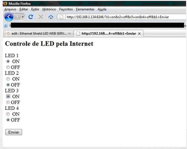 Fig. 1. Control LEDs through the browser.
The W5500 module is based on the W5500 chip itself with its padding, as well as the BLS connector of the MK for SPI connection, the RJ-45 connector for connecting to a computer network, and the 3.3V linear supply voltage regulator (Fig. 2).

Fig. 2. Module W5500.
The W5500 chip is a full-fledged controller that incorporates processing of a whole stack of network protocols, ranging from Ethernet to TCP (Fig. 3). When implementing a design based on this chip, the programmer does not need to write TCP / IP protocol processing code; all you need is to implement only the application layer protocol that will be nested in TCP. In the example above (on Arduino), http is used as the application protocol.
 Fig. 3. The structure of the chip W5500.
Without being engaged in Arduino, I decided to study in detail the documentation for the W5500 chip and independently implement the program based on the Atmega8 microcontroller. This program will not provide an http handler. It is required to implement the simplest (RAW) data exchange via the TCP protocol using a remote terminal. It’s not quite accurate to talk about the Telnet protocol, as the title of this article says. It has its own specific features based on the exchange of additional information about the parameters of the terminals. However, most telnet clients support RAW and do not require the above. Thus, the Atmega8 MK program will not provide for an application-level protocol handler. It will only deal with W5500 initialization, managing sockets, receiving and transmitting data.
The main application of this design is device management via a remote terminal. In this case, the construction is connected to the controlled device via the UART interface (three wires GND, TxD, RxD). Terminal management is a classic professional approach in a particular area in the absence of a graphical interface. For example, the command line of Windows or Linux, or a method of setting up a router via a terminal using the Telnet protocol. The last example is actually equivalent to the idea in question in this article.
When developing a device, if necessary, I provide for the management of text commands through a terminal that is connected via a UART interface. This can be a connection to a standard PC to a RS-232 COM port via a MAX232 adapter chip, or to a USB (virtual COM port) via a PL2303 chip. As a terminal, you can use the standard program HyperTerminal. With the proliferation of Android-based smartphones, it became convenient to connect via Bluetooth: a Bluetooth module (for example, HC-06) is connected to the device's UART interface, and the smartphone is connected to the module wirelessly. On the Internet, many applications that implement the terminal via Bluetooth. Thus, it is possible to control the device via the terminal from a mobile phone via Bluetooth in a small radius of action. Design, This article allows you to implement control through the terminal using the Internet. A standard HyperTerminal, which comes with Windows XP, can act as a terminal, or you can run the telnet utility from the Windows command line and work in it. If we are talking about a smartphone, then you can choose one of the applications on Android (they are also a great many) (Fig. 4).
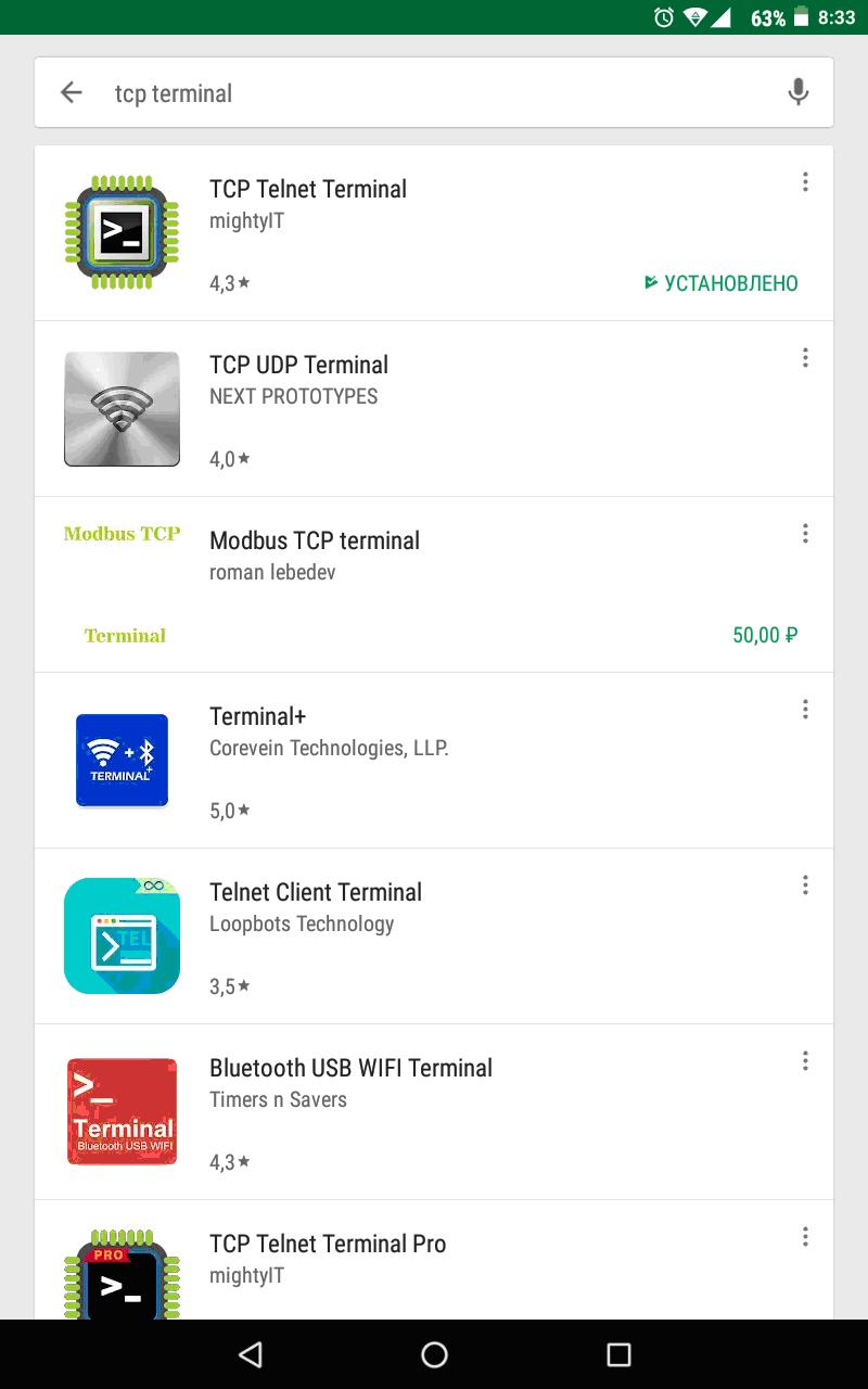
Fig. 4. Applications for the request "TCP terminal" on Google Play.
The W5500 chip has 8 independent sockets, each of which has a memory for receiving and transmitting information on 2 KB. Total, the general memory 16 KB on reception and 16 KB on information transfer. These parameters are applied by default, but if necessary at the chip initialization stage, memory can be redistributed by socket. The application described here will use the default memory settings and will use all 8 sockets. Each socket at the stage of its initialization is assigned a set of parameters, the main of which are its mode of operation and the TCP port. The mode of operation of all eight sockets that we need is TCP server mode. You must assign each port a different port. I took eight consecutive ports, starting, for example, from 4000. At the initialization stage of the W5500 module, the network parameters are assigned to the Atmega8 MK program: The IP address, subnet mask, gateway IP address and even the physical MAC address. The network settings of the W5500 module must match the settings of the home network to which it is connected. When remotely connecting to our described device, the terminal settings indicate the node address (IP address or domain name) and port. The host address refers to the W5500 device, and the port refers to the socket in the device. One socket can work with only one connection. Therefore, it is possible to make eight independent simultaneous connections. Figure 5 shows the connection parameters in the standard HyperTerminal program to the W5500 with the IP address 192.168.0.111 to socket 0 (port 4000). To connect to the global Internet (outside), you need to properly configure your home router. The network settings of the W5500 module must match the settings of the home network to which it is connected. When remotely connecting to our described device, the terminal settings indicate the node address (IP address or domain name) and port. The host address refers to the W5500 device, and the port refers to the socket in the device. One socket can work with only one connection. Therefore, it is possible to make eight independent simultaneous connections. Figure 5 shows the connection parameters in the standard HyperTerminal program to the W5500 with the IP address 192.168.0.111 to socket 0 (port 4000). To connect to the global Internet (outside), you need to properly configure your home router. The network settings of the W5500 module must match the settings of the home network to which it is connected. When remotely connecting to our described device, the terminal settings indicate the node address (IP address or domain name) and port. The host address refers to the W5500 device, and the port refers to the socket in the device. One socket can work with only one connection. Therefore, it is possible to make eight independent simultaneous connections. Figure 5 shows the connection parameters in the standard HyperTerminal program to the W5500 with the IP address 192.168.0.111 to socket 0 (port 4000). To connect to the global Internet (outside), you need to properly configure your home router. When remotely connecting to our described device, the terminal settings indicate the node address (IP address or domain name) and port. The host address refers to the W5500 device, and the port refers to the socket in the device. One socket can work with only one connection. Therefore, it is possible to make eight independent simultaneous connections. Figure 5 shows the connection parameters in the standard HyperTerminal program to the W5500 with the IP address 192.168.0.111 to socket 0 (port 4000). To connect to the global Internet (outside), you need to properly configure your home router. When remotely connecting to our described device, the terminal settings indicate the node address (IP address or domain name) and port. The host address refers to the W5500 device, and the port refers to the socket in the device. One socket can work with only one connection. Therefore, it is possible to make eight independent simultaneous connections. Figure 5 shows the connection parameters in the standard HyperTerminal program to the W5500 with the IP address 192.168.0.111 to socket 0 (port 4000). To connect to the global Internet (outside), you need to properly configure your home router. It is possible to make eight independent simultaneous connections. Figure 5 shows the connection parameters in the standard HyperTerminal program to the W5500 with the IP address 192.168.0.111 to socket 0 (port 4000). To connect to the global Internet (outside), you need to properly configure your home router. It is possible to make eight independent simultaneous connections. Figure 5 shows the connection parameters in the standard HyperTerminal program to the W5500 with the IP address 192.168.0.111 to socket 0 (port 4000). To connect to the global Internet (outside), you need to properly configure your home router.
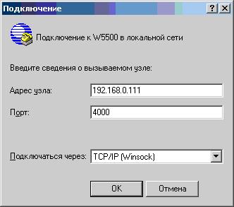 Fig. 5. Connection via TCP / IP to HyperTerminal.
I tried many different TCP terminal applications, each with its own advantages and disadvantages. First of all, according to the method of packing a TCP packet, two cases can be distinguished. In the first case, the TCP packet is generated and sent to the server immediately with the character entered in the terminal. Thus, the data field of each packet occupies 1 byte and contains the character entered by the user. The HyperTerminal program works just in this mode. In the second case, the character set (command) is entered into a separate text field, and when you click on the "Send" button, only one package is formed with a data field, the contents of which is a character set entered by the user. The size of the data field of such a package in bytes is the same as the number of characters entered. The second case is the most preferred and convenient, as well as economical in traffic.
As for the organization of the transfer of information from the server to the client, here too there are some peculiarities. You can also make the one-byte TCP packet the MK program also directly, upon receipt of one byte (character) on the RxD UART MK leg. You can make the formation of a TCP packet from the set of incoming bytes on the MC by the presence of a special additional signal, which is present only during the transmission of the sequence from the connected device (packing signal). By the way, this signal is used for switching MAX485 to transmit in case of RS-232 conversion to half-duplex RS-485 interface. However, as I was convinced, it is most convenient to use a timer, i.e. a small delay during which the reception of characters and the formation of a TCP packet will be made. This is the method I implemented in the described construction. It works as follows. The timer (time is set to approximately 0.3 seconds) starts when the first character arrives and is reset when each next character arrives at the UART MK. If within the specified time the characters did not arrive, the packet with the received characters is formed and sent to the client, and the timer stops. In my particular case, there is a massive mailing on all the sockets to which clients are connected.
Now it's about privacy. The described remote terminal is not protected from “eavesdropping” using traffic analyzers. Even the Telnet protocol itself does not provide for password authentication and encryption. For this, there are other modern remote terminal protocols. And in the case of Telnet, as in the case of RAW (without an application protocol), an indirect method of password authorization can be implemented, except perhaps ineffective with intentional intentional intervention. However, this authentication method will protect against uncontrolled "left" traffic. It can come from spyware, which, going through a range of IP addresses of well-known providers and a range of ports, can suddenly connect to our device (if it “listens” to connections from the Internet). In my firmware, I implemented a customer welcome page, if he connects to the server, i.e. to the design based on the W5500 module.
The welcome page contains information about the client's IP address, socket number (for control), and a suggestion to enter a password (Fig. 6).
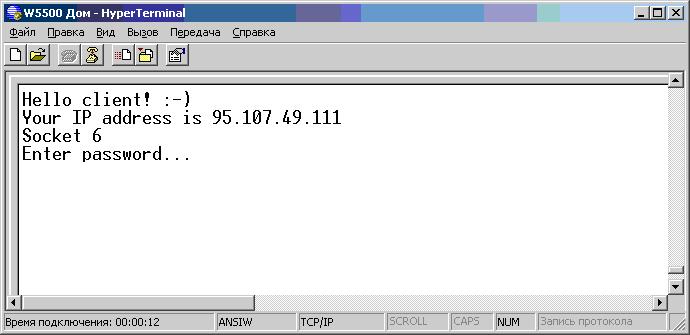 Fig. 6. Welcome page of W5500 server.
After connecting within the MK program, a timer is started for a time (approximately 18 seconds), during which the user must have time to enter a specific password (the same on all sockets). In the case of an incorrectly entered password, after the specified time has elapsed, the user informs the corresponding message, and the server terminates the connection (Fig. 7).
 Fig. 7. Message about incorrect password.
In the case of a correctly entered password, the corresponding message is also displayed to the user (Fig. 8). After that, a “transparent” bridge is established between the remote terminal and the UART interface of the MK, to which the W5500 module is connected via SPI. The operation of such a bridge was checked only at the level of user commands. A full-fledged high-speed data exchange may not be guaranteed if, in any cases, the client application is not a user terminal, but some other program. And even more so, in the described design is not guaranteed (more precisely, not provided) full-duplex data exchange.
 Fig. 8. Message about the correct password.
When entering a password, the characters entered by the user are not returned to the terminal, and “Backspace” does not work (rollback if the character is entered incorrectly). Password length - 8 characters. The MK program scans the first 8 characters that came from the client, regardless of their distribution over TCP packets. But any packet should not exceed 10 bytes. By the way, the “Send Text File” function in HyperTerminal works quite interestingly. As it was checked using the traffic analyzer, when performing this function, two TCP packets are formed: the first packet with data in 1 byte contains the first character of the transmitted text file, and the second packet contains all other content.
The server provides two different passwords. One password is used to establish the TCP-UART bridge (normal use), as mentioned above, and the second password is used to control the W5500 module or other design parameters. If you enter this password, the user is displayed another welcome page, and he enters the control mode. I intentionally provided that this mode was possible only on one of the free sockets. If a socket with this mode is busy, and an attempt is made to log in to this mode on another socket, the connection will be immediately terminated by the server. Before breaking, a message will be displayed about the number of the socket, which is already working (busy) in the management mode (Fig. 9).
The control mode provides for the commands defined by me, the list of which can be seen by entering the “help” command. The command must end with a new-line transfer character (the Enter key). In addition, if the management mode is active, the W5500 server issues service messages to the terminal, for example, about connecting clients to other sockets with their IP addresses or about a free socket. Figure 10 illustrates the above. The list of teams is not yet complete, it will be replenished over time.
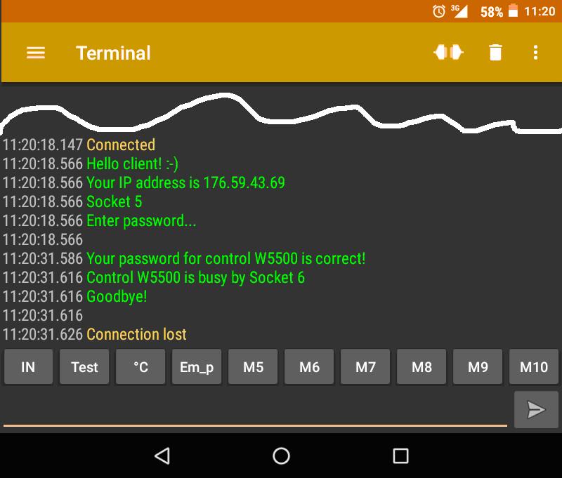
Fig. 9. Message about the busy socket when entering the control mode password.
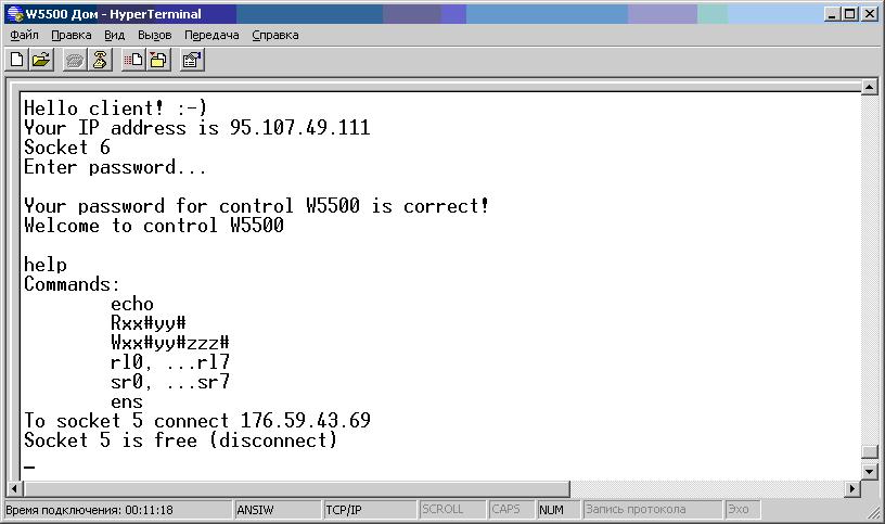 Fig. 10. W5500 control mode.
The "echo" command disables or enables the return of the printed character to the terminal (self-checking). The following two commands are for reading and writing the address register of the W5500 chip. Register values by addresses are specified in the documentation for the W5500 chip. I introduced these universal commands primarily for debugging. The "rl" command immediately "reloads" the socket, the number of which is indicated after. Similarly, the “sr” command reads the status of a socket, displaying its value as a HEX number. The command “ens” gives the state table of each socket: state “0” - the socket is free, waiting for the client, state “1” - the socket in the normal use mode, state “2” - the socket in the control mode. You can enter a much larger number of commands. It will be useful to change the parameters that fit into the chip at the initialization stage when the device is turned on (for example, network parameters), storing them in non-volatile memory MK. It may also be useful to introduce special commands that will manage additional free MK pins. For example, “PC0 = 1”, “PC2 = 0”, etc. Be sure to need the configuration command UART interface MK.
Consider the finer details of the program MK. In addition to the above-listed timers, a timer is activated, due to which every approximately half a minute so-called are sent to all the involved sockets. control TCP packets "keep-alive". This is needed to test the connection in the absence of user data exchange. If, for any reason, the client does not receive a response with confirmation within a certain time period established within the W5500, the so-called operation will occur. timeout and the socket will be reloaded. The connection may suddenly be lost, for example, due to a breakdown on the link or physical layer: the Ethernet cable was pulled out, the Internet was disconnected or the Wi-Fi connection was lost, etc.
Based on the documentation for the W5500 chip (datasheet), the following functions are implemented in the program code. First, the basic functions of writing and reading registers of the W5500 by addresses. The top level functions are hardware reset, chip initialization, socket initialization, socket opening, listening socket, disconnecting and closing the socket, sending the keep_alive command, and reloading the socket. The latter function is a composition of the above functions: close, open, listen. Most functions return the status of the socket after they are executed. Finally, the most basic functions are processing the received information (reading from the RX buffer) and processing the sent information (writing to the TX buffer). I took recommendations on the implementation of these functions from the official site of the chip manufacturer W5500 ( link). The receive function rewrites the received data from the RX buffer into its own buffer (not circular), 128 bytes in size. This size is quite enough for simple applications, and you will not take much from the Atmega8 microcontroller. The transfer function overwrites data from the intermediate buffer, which is also small, to the TX buffer W5500. And in turn, data from the UART ring buffer is in turn entered. The latter is implemented automatically in the CVAVR development environment with the help of the auxiliary CodeWizardAVR application at the stage of project creation.
The W5500 module is connected to the SPI interface MK (MOSI, MISO, SCK, SCLK). In addition, the output RST (hardware reset) is connected to a certain MK output, and the corresponding INT input is connected to the external interrupt input INT0. The latter is used for its intended purpose: When an event occurs in the W5500 module, it generates a pulse at the INT pin, which is processed by the controller in the body of an external interrupt. The MC learns on which sockets the event occurred, then rewrites the event codes for each socket into a specific array. Further interrupt processing occurs within the main program loop. A total of five events were documented: the client connected, the client disconnected (more precisely, submitted a request to disconnect), data came from the client, the timeout worked, the data was sent successfully. In the main loop, all events are handled. except the last. The switch-case statement is placed in this processing. The largest part of the C program code is found in the third event processing section (data reception). In it, after the function of processing received information, the switch-case statement is also placed, but in this case this “switch” is associated with a variable responsible for the state of the socket, which was mentioned above (values 0, 1, 2). The first section is responsible for the password recognition procedure. Accepted characters are written to a separate password buffer. Under certain conditions, functions of comparing the received string with constant strings containing passwords work. In the case of a match, the corresponding state is assigned. The second section is the simplest - the contents of its own buffer of received information is redirected to the UART microcontroller. This is the normal use mode. The third section (the largest) is responsible for processing commands - the device control mode.
In addition to continuing the interrupt handler in the main program loop, virtual timers are placed — a timeout for breaking the connection in an unsuccessful attempt to enter a password, periodic “keep-alive” sending and sending a TCP-generated packet to the client. The function of reading from the UART is placed in the body of the main loop, inside which the characters received by the controller are rewritten into its own (intermediate) transfer buffer and the timer is reset, which is responsible for the formation of a TCP packet.
All socket procedures are placed in a loop from 0 to 7, the iterator of which is bound to the socket number. Thus, all the sockets are processed sequentially. Initially, I meant that if you assigned the same port number to each of the eight sockets, you can connect up to eight users on the same port. However, this configuration did not work, and this issue is still pending for the future.
In developing a printed circuit board design, I provided a real-time clock (RTC) on a DS1307 chip. The double-sided printed circuit board contains Atmega8 MK, quartz at a frequency of 11.0592 MHz (frequency selected for UART accuracy), a connector for the W5500 module, connectors for the MK ports (including SPI for firmware, UART), RTC with its own quartz and a CR2032 battery compartment , 5V linear regulator (7805), power connector, and more. A sketch of the printed circuit board in the Sprint Layout program is shown in Figure 11. The only element that is shown in red is soldered on the reverse side, but I soldered it to the front side.
 Fig. 11. Sketch of the circuit board.
Photos of the finished structure are shown in Figure 12. The clock in this design will be used for time stamping at certain events of W5500 sockets, and this time will be assigned to the user in the terminal next to the message if the user is connected in control mode. And also, the clock will be useful for the future for experiments with the NTP time setting protocol or for any other purposes.
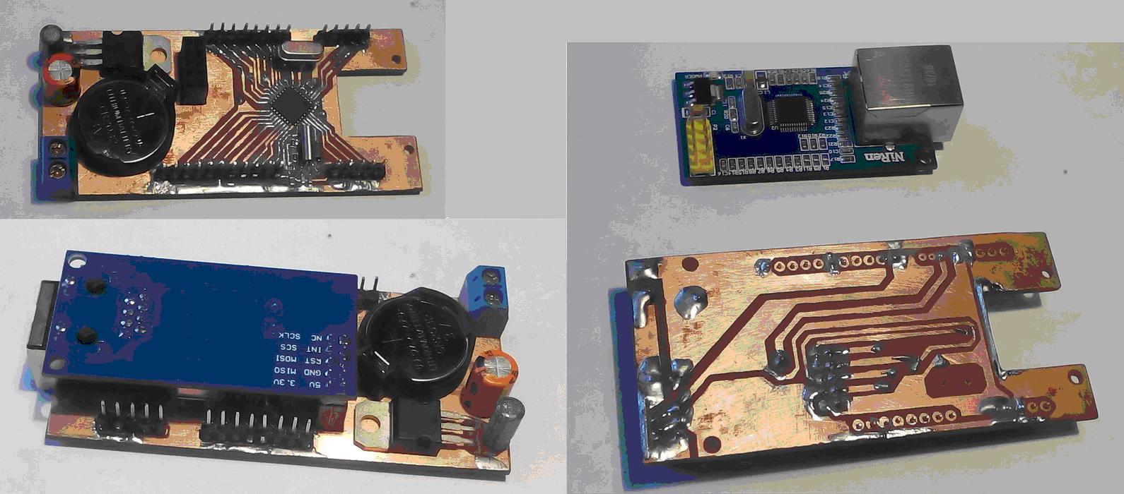 Fig. 12. Photos of the finished design.
In conclusion, it is worth noting that the design of its own production for the most part justifies similar industrial-level devices. The main advantage is the price. It turned out to be much cheaper to produce than the price of a finished similar device. And such a flaw as limited functionality is inevitable. In this case, a simplified Atmega8 controller was used, since the corresponding simplified goal was set.
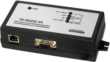 Fig. 13. Industrial TCP / IP Converter - RS-232.
In Figure 13, as an example, an industrial TCP / IP to RS-232 converter is shown, based on the W5100 chip, very similar to the W5500. He, in addition to a flexible management interface, has another advantage. In addition to working with a TCP / IP terminal, it is possible to install a virtual COM port on the client side using a special driver that comes with the device. Through it, you can connect using a standard terminal that does not have a TCP / IP connection mode. Moreover, the device can support full-fledged RS-232 data exchange if, instead of a terminal, a program is connected via a virtual COM port. That is, the device shown in Figure 13 is a full-fledged RS-232 bridge over the network infrastructure.
One of the modules - W5500 - is intended for the manufacture of electronic structures that will be connected to the Internet. In this case, most often, it means remote control of its structure. For example, it could be a “smart home”, a robot, and the like. The most trivial project (except for Hello world) is the remote activation of LEDs through a web browser (Fig. 1). If instead of the LEDs connect the transistor switches and relays, you can switch more powerful loads. Thus, in essence, the program (firmware) of this design is a web server that processes http requests from a remote user.
The W5500 module is based on the W5500 chip itself with its padding, as well as the BLS connector of the MK for SPI connection, the RJ-45 connector for connecting to a computer network, and the 3.3V linear supply voltage regulator (Fig. 2).
Fig. 2. Module W5500.
The W5500 chip is a full-fledged controller that incorporates processing of a whole stack of network protocols, ranging from Ethernet to TCP (Fig. 3). When implementing a design based on this chip, the programmer does not need to write TCP / IP protocol processing code; all you need is to implement only the application layer protocol that will be nested in TCP. In the example above (on Arduino), http is used as the application protocol.
Without being engaged in Arduino, I decided to study in detail the documentation for the W5500 chip and independently implement the program based on the Atmega8 microcontroller. This program will not provide an http handler. It is required to implement the simplest (RAW) data exchange via the TCP protocol using a remote terminal. It’s not quite accurate to talk about the Telnet protocol, as the title of this article says. It has its own specific features based on the exchange of additional information about the parameters of the terminals. However, most telnet clients support RAW and do not require the above. Thus, the Atmega8 MK program will not provide for an application-level protocol handler. It will only deal with W5500 initialization, managing sockets, receiving and transmitting data.
The main application of this design is device management via a remote terminal. In this case, the construction is connected to the controlled device via the UART interface (three wires GND, TxD, RxD). Terminal management is a classic professional approach in a particular area in the absence of a graphical interface. For example, the command line of Windows or Linux, or a method of setting up a router via a terminal using the Telnet protocol. The last example is actually equivalent to the idea in question in this article.
When developing a device, if necessary, I provide for the management of text commands through a terminal that is connected via a UART interface. This can be a connection to a standard PC to a RS-232 COM port via a MAX232 adapter chip, or to a USB (virtual COM port) via a PL2303 chip. As a terminal, you can use the standard program HyperTerminal. With the proliferation of Android-based smartphones, it became convenient to connect via Bluetooth: a Bluetooth module (for example, HC-06) is connected to the device's UART interface, and the smartphone is connected to the module wirelessly. On the Internet, many applications that implement the terminal via Bluetooth. Thus, it is possible to control the device via the terminal from a mobile phone via Bluetooth in a small radius of action. Design, This article allows you to implement control through the terminal using the Internet. A standard HyperTerminal, which comes with Windows XP, can act as a terminal, or you can run the telnet utility from the Windows command line and work in it. If we are talking about a smartphone, then you can choose one of the applications on Android (they are also a great many) (Fig. 4).
Fig. 4. Applications for the request "TCP terminal" on Google Play.
The W5500 chip has 8 independent sockets, each of which has a memory for receiving and transmitting information on 2 KB. Total, the general memory 16 KB on reception and 16 KB on information transfer. These parameters are applied by default, but if necessary at the chip initialization stage, memory can be redistributed by socket. The application described here will use the default memory settings and will use all 8 sockets. Each socket at the stage of its initialization is assigned a set of parameters, the main of which are its mode of operation and the TCP port. The mode of operation of all eight sockets that we need is TCP server mode. You must assign each port a different port. I took eight consecutive ports, starting, for example, from 4000. At the initialization stage of the W5500 module, the network parameters are assigned to the Atmega8 MK program: The IP address, subnet mask, gateway IP address and even the physical MAC address. The network settings of the W5500 module must match the settings of the home network to which it is connected. When remotely connecting to our described device, the terminal settings indicate the node address (IP address or domain name) and port. The host address refers to the W5500 device, and the port refers to the socket in the device. One socket can work with only one connection. Therefore, it is possible to make eight independent simultaneous connections. Figure 5 shows the connection parameters in the standard HyperTerminal program to the W5500 with the IP address 192.168.0.111 to socket 0 (port 4000). To connect to the global Internet (outside), you need to properly configure your home router. The network settings of the W5500 module must match the settings of the home network to which it is connected. When remotely connecting to our described device, the terminal settings indicate the node address (IP address or domain name) and port. The host address refers to the W5500 device, and the port refers to the socket in the device. One socket can work with only one connection. Therefore, it is possible to make eight independent simultaneous connections. Figure 5 shows the connection parameters in the standard HyperTerminal program to the W5500 with the IP address 192.168.0.111 to socket 0 (port 4000). To connect to the global Internet (outside), you need to properly configure your home router. The network settings of the W5500 module must match the settings of the home network to which it is connected. When remotely connecting to our described device, the terminal settings indicate the node address (IP address or domain name) and port. The host address refers to the W5500 device, and the port refers to the socket in the device. One socket can work with only one connection. Therefore, it is possible to make eight independent simultaneous connections. Figure 5 shows the connection parameters in the standard HyperTerminal program to the W5500 with the IP address 192.168.0.111 to socket 0 (port 4000). To connect to the global Internet (outside), you need to properly configure your home router. When remotely connecting to our described device, the terminal settings indicate the node address (IP address or domain name) and port. The host address refers to the W5500 device, and the port refers to the socket in the device. One socket can work with only one connection. Therefore, it is possible to make eight independent simultaneous connections. Figure 5 shows the connection parameters in the standard HyperTerminal program to the W5500 with the IP address 192.168.0.111 to socket 0 (port 4000). To connect to the global Internet (outside), you need to properly configure your home router. When remotely connecting to our described device, the terminal settings indicate the node address (IP address or domain name) and port. The host address refers to the W5500 device, and the port refers to the socket in the device. One socket can work with only one connection. Therefore, it is possible to make eight independent simultaneous connections. Figure 5 shows the connection parameters in the standard HyperTerminal program to the W5500 with the IP address 192.168.0.111 to socket 0 (port 4000). To connect to the global Internet (outside), you need to properly configure your home router. It is possible to make eight independent simultaneous connections. Figure 5 shows the connection parameters in the standard HyperTerminal program to the W5500 with the IP address 192.168.0.111 to socket 0 (port 4000). To connect to the global Internet (outside), you need to properly configure your home router. It is possible to make eight independent simultaneous connections. Figure 5 shows the connection parameters in the standard HyperTerminal program to the W5500 with the IP address 192.168.0.111 to socket 0 (port 4000). To connect to the global Internet (outside), you need to properly configure your home router.
I tried many different TCP terminal applications, each with its own advantages and disadvantages. First of all, according to the method of packing a TCP packet, two cases can be distinguished. In the first case, the TCP packet is generated and sent to the server immediately with the character entered in the terminal. Thus, the data field of each packet occupies 1 byte and contains the character entered by the user. The HyperTerminal program works just in this mode. In the second case, the character set (command) is entered into a separate text field, and when you click on the "Send" button, only one package is formed with a data field, the contents of which is a character set entered by the user. The size of the data field of such a package in bytes is the same as the number of characters entered. The second case is the most preferred and convenient, as well as economical in traffic.
As for the organization of the transfer of information from the server to the client, here too there are some peculiarities. You can also make the one-byte TCP packet the MK program also directly, upon receipt of one byte (character) on the RxD UART MK leg. You can make the formation of a TCP packet from the set of incoming bytes on the MC by the presence of a special additional signal, which is present only during the transmission of the sequence from the connected device (packing signal). By the way, this signal is used for switching MAX485 to transmit in case of RS-232 conversion to half-duplex RS-485 interface. However, as I was convinced, it is most convenient to use a timer, i.e. a small delay during which the reception of characters and the formation of a TCP packet will be made. This is the method I implemented in the described construction. It works as follows. The timer (time is set to approximately 0.3 seconds) starts when the first character arrives and is reset when each next character arrives at the UART MK. If within the specified time the characters did not arrive, the packet with the received characters is formed and sent to the client, and the timer stops. In my particular case, there is a massive mailing on all the sockets to which clients are connected.
Now it's about privacy. The described remote terminal is not protected from “eavesdropping” using traffic analyzers. Even the Telnet protocol itself does not provide for password authentication and encryption. For this, there are other modern remote terminal protocols. And in the case of Telnet, as in the case of RAW (without an application protocol), an indirect method of password authorization can be implemented, except perhaps ineffective with intentional intentional intervention. However, this authentication method will protect against uncontrolled "left" traffic. It can come from spyware, which, going through a range of IP addresses of well-known providers and a range of ports, can suddenly connect to our device (if it “listens” to connections from the Internet). In my firmware, I implemented a customer welcome page, if he connects to the server, i.e. to the design based on the W5500 module.
The welcome page contains information about the client's IP address, socket number (for control), and a suggestion to enter a password (Fig. 6).
After connecting within the MK program, a timer is started for a time (approximately 18 seconds), during which the user must have time to enter a specific password (the same on all sockets). In the case of an incorrectly entered password, after the specified time has elapsed, the user informs the corresponding message, and the server terminates the connection (Fig. 7).
In the case of a correctly entered password, the corresponding message is also displayed to the user (Fig. 8). After that, a “transparent” bridge is established between the remote terminal and the UART interface of the MK, to which the W5500 module is connected via SPI. The operation of such a bridge was checked only at the level of user commands. A full-fledged high-speed data exchange may not be guaranteed if, in any cases, the client application is not a user terminal, but some other program. And even more so, in the described design is not guaranteed (more precisely, not provided) full-duplex data exchange.
When entering a password, the characters entered by the user are not returned to the terminal, and “Backspace” does not work (rollback if the character is entered incorrectly). Password length - 8 characters. The MK program scans the first 8 characters that came from the client, regardless of their distribution over TCP packets. But any packet should not exceed 10 bytes. By the way, the “Send Text File” function in HyperTerminal works quite interestingly. As it was checked using the traffic analyzer, when performing this function, two TCP packets are formed: the first packet with data in 1 byte contains the first character of the transmitted text file, and the second packet contains all other content.
The server provides two different passwords. One password is used to establish the TCP-UART bridge (normal use), as mentioned above, and the second password is used to control the W5500 module or other design parameters. If you enter this password, the user is displayed another welcome page, and he enters the control mode. I intentionally provided that this mode was possible only on one of the free sockets. If a socket with this mode is busy, and an attempt is made to log in to this mode on another socket, the connection will be immediately terminated by the server. Before breaking, a message will be displayed about the number of the socket, which is already working (busy) in the management mode (Fig. 9).
The control mode provides for the commands defined by me, the list of which can be seen by entering the “help” command. The command must end with a new-line transfer character (the Enter key). In addition, if the management mode is active, the W5500 server issues service messages to the terminal, for example, about connecting clients to other sockets with their IP addresses or about a free socket. Figure 10 illustrates the above. The list of teams is not yet complete, it will be replenished over time.
Fig. 9. Message about the busy socket when entering the control mode password.
The "echo" command disables or enables the return of the printed character to the terminal (self-checking). The following two commands are for reading and writing the address register of the W5500 chip. Register values by addresses are specified in the documentation for the W5500 chip. I introduced these universal commands primarily for debugging. The "rl" command immediately "reloads" the socket, the number of which is indicated after. Similarly, the “sr” command reads the status of a socket, displaying its value as a HEX number. The command “ens” gives the state table of each socket: state “0” - the socket is free, waiting for the client, state “1” - the socket in the normal use mode, state “2” - the socket in the control mode. You can enter a much larger number of commands. It will be useful to change the parameters that fit into the chip at the initialization stage when the device is turned on (for example, network parameters), storing them in non-volatile memory MK. It may also be useful to introduce special commands that will manage additional free MK pins. For example, “PC0 = 1”, “PC2 = 0”, etc. Be sure to need the configuration command UART interface MK.
Consider the finer details of the program MK. In addition to the above-listed timers, a timer is activated, due to which every approximately half a minute so-called are sent to all the involved sockets. control TCP packets "keep-alive". This is needed to test the connection in the absence of user data exchange. If, for any reason, the client does not receive a response with confirmation within a certain time period established within the W5500, the so-called operation will occur. timeout and the socket will be reloaded. The connection may suddenly be lost, for example, due to a breakdown on the link or physical layer: the Ethernet cable was pulled out, the Internet was disconnected or the Wi-Fi connection was lost, etc.
Based on the documentation for the W5500 chip (datasheet), the following functions are implemented in the program code. First, the basic functions of writing and reading registers of the W5500 by addresses. The top level functions are hardware reset, chip initialization, socket initialization, socket opening, listening socket, disconnecting and closing the socket, sending the keep_alive command, and reloading the socket. The latter function is a composition of the above functions: close, open, listen. Most functions return the status of the socket after they are executed. Finally, the most basic functions are processing the received information (reading from the RX buffer) and processing the sent information (writing to the TX buffer). I took recommendations on the implementation of these functions from the official site of the chip manufacturer W5500 ( link). The receive function rewrites the received data from the RX buffer into its own buffer (not circular), 128 bytes in size. This size is quite enough for simple applications, and you will not take much from the Atmega8 microcontroller. The transfer function overwrites data from the intermediate buffer, which is also small, to the TX buffer W5500. And in turn, data from the UART ring buffer is in turn entered. The latter is implemented automatically in the CVAVR development environment with the help of the auxiliary CodeWizardAVR application at the stage of project creation.
The W5500 module is connected to the SPI interface MK (MOSI, MISO, SCK, SCLK). In addition, the output RST (hardware reset) is connected to a certain MK output, and the corresponding INT input is connected to the external interrupt input INT0. The latter is used for its intended purpose: When an event occurs in the W5500 module, it generates a pulse at the INT pin, which is processed by the controller in the body of an external interrupt. The MC learns on which sockets the event occurred, then rewrites the event codes for each socket into a specific array. Further interrupt processing occurs within the main program loop. A total of five events were documented: the client connected, the client disconnected (more precisely, submitted a request to disconnect), data came from the client, the timeout worked, the data was sent successfully. In the main loop, all events are handled. except the last. The switch-case statement is placed in this processing. The largest part of the C program code is found in the third event processing section (data reception). In it, after the function of processing received information, the switch-case statement is also placed, but in this case this “switch” is associated with a variable responsible for the state of the socket, which was mentioned above (values 0, 1, 2). The first section is responsible for the password recognition procedure. Accepted characters are written to a separate password buffer. Under certain conditions, functions of comparing the received string with constant strings containing passwords work. In the case of a match, the corresponding state is assigned. The second section is the simplest - the contents of its own buffer of received information is redirected to the UART microcontroller. This is the normal use mode. The third section (the largest) is responsible for processing commands - the device control mode.
In addition to continuing the interrupt handler in the main program loop, virtual timers are placed — a timeout for breaking the connection in an unsuccessful attempt to enter a password, periodic “keep-alive” sending and sending a TCP-generated packet to the client. The function of reading from the UART is placed in the body of the main loop, inside which the characters received by the controller are rewritten into its own (intermediate) transfer buffer and the timer is reset, which is responsible for the formation of a TCP packet.
All socket procedures are placed in a loop from 0 to 7, the iterator of which is bound to the socket number. Thus, all the sockets are processed sequentially. Initially, I meant that if you assigned the same port number to each of the eight sockets, you can connect up to eight users on the same port. However, this configuration did not work, and this issue is still pending for the future.
In developing a printed circuit board design, I provided a real-time clock (RTC) on a DS1307 chip. The double-sided printed circuit board contains Atmega8 MK, quartz at a frequency of 11.0592 MHz (frequency selected for UART accuracy), a connector for the W5500 module, connectors for the MK ports (including SPI for firmware, UART), RTC with its own quartz and a CR2032 battery compartment , 5V linear regulator (7805), power connector, and more. A sketch of the printed circuit board in the Sprint Layout program is shown in Figure 11. The only element that is shown in red is soldered on the reverse side, but I soldered it to the front side.
Photos of the finished structure are shown in Figure 12. The clock in this design will be used for time stamping at certain events of W5500 sockets, and this time will be assigned to the user in the terminal next to the message if the user is connected in control mode. And also, the clock will be useful for the future for experiments with the NTP time setting protocol or for any other purposes.
In conclusion, it is worth noting that the design of its own production for the most part justifies similar industrial-level devices. The main advantage is the price. It turned out to be much cheaper to produce than the price of a finished similar device. And such a flaw as limited functionality is inevitable. In this case, a simplified Atmega8 controller was used, since the corresponding simplified goal was set.
In Figure 13, as an example, an industrial TCP / IP to RS-232 converter is shown, based on the W5100 chip, very similar to the W5500. He, in addition to a flexible management interface, has another advantage. In addition to working with a TCP / IP terminal, it is possible to install a virtual COM port on the client side using a special driver that comes with the device. Through it, you can connect using a standard terminal that does not have a TCP / IP connection mode. Moreover, the device can support full-fledged RS-232 data exchange if, instead of a terminal, a program is connected via a virtual COM port. That is, the device shown in Figure 13 is a full-fledged RS-232 bridge over the network infrastructure.