Capacitive touch sensor without external strapping on the STM32 Discovery
Earlier this year, a worthy citizen of Ariman wrote an article on how to screw a capacitive touch sensor to a microcontroller. This idea seemed quite promising to me, for some devices touch keys would fit much better than mechanical ones. In this article I will talk about my implementation of this useful technology based on the STM32 Discovery debug board.
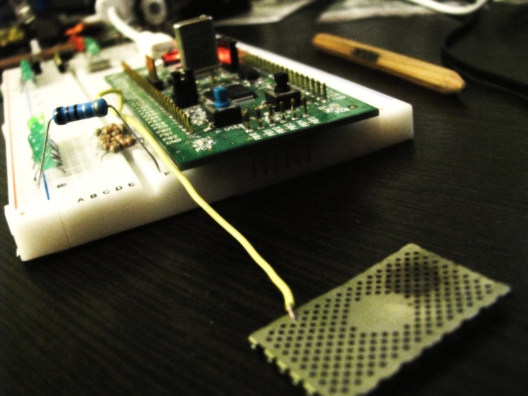
So, just starting to learn STM32, I decided as an exercise to add to the device the ability to detect touch. Having started to understand theory and practice in the aforementioned article, I repeated the scheme of Comrade Ariman'a. It worked perfectly, but I, a lover of minimalism, wanted to simplify it, getting rid of unnecessary elements. In my opinion, the external resistor and the power path turned out to be superfluous. All this is already in most microcontrollers, including AVR and STM32. I mean pull-up resistors of input / output ports. Why not charge the plate and our fingers through them? In anticipation of a trick, I put together a circuit on a breadboard, which, to my surprise, worked the first time. As a matter of fact, it’s even funny to call this a circuit, because all we need to do is simply connect the contact plate to the leg of the debug board. The microcontroller will take care of all the work.
What is the program like? Firstly, two functions:
The first displays a logical “0” on the sensor leg (zero pin of register C)
void Sensor_Ground (void)
{
	GPIOC->CRL = 0x1;
	GPIOC->BRR |= 0x1;
}
The second sets up the same output to the input, with a pull-up to the power.
void Sensor_InPullUp (void)
{
	GPIOC->CRL = 0x8;
	GPIOC->BSRR |= 0x1;
}
Now, at the beginning of the polling cycle, we call Sensor_Ground (), and wait a while to discharge all the residual charge on the sensor to the ground. Then we reset the count variable, which we will take into account the charging time of the sensor and call Sensor_InPullUp ().
Sensor_Ground();
Delay(0xFF);    //простой пустой счётчик
count = 0;
Sensor_InPullUp();
Now the sensor begins to charge through an internal pull-up resistor with a face value of the order of tens of KOhms (30..50KOhm for STM32). The time constant of such a circuit will be equal to a few clock cycles, so I changed the quartz resonator on the debug board to a faster one, 20 MHz (by the way, I did not immediately notice what happens on the STM32 Discovery quartz changes without soldering). So, we count the processor cycles until a logical unit appears at the input:
while(!(GPIOC->IDR & 0x1))
    	{
    		count++;
    	}
After exiting this cycle, the count variable will store a number proportional to the capacity of the sensor plate. In my case, with a 20 MHz chip, the count value is 1 when not pressed, 7-10 with the lightest touch, 15-20 with a normal touch. All that remains is to compare it with the threshold value and remember to call Sensor_Ground () again so that the sensor is already discharged by the next polling cycle.
The resulting sensitivity is enough to confidently determine touches to bare metal areas. When covering the sensor with a sheet of paper or plastic, the sensitivity drops three to four times, only sure presses are well defined. To increase the sensitivity when the sensor needs to be covered with protective material, the clock frequency of the microcontroller can be increased.
Compared to Ariman's implementation , my approach works much faster (about a dozen clock cycles for polling one sensor), so I did not complicate the program by setting timer interrupts.
Finally, a video demonstrating the operation of the sensor.
Main.c test program.
Reference Manual on the microcontroller
Thank user ALPINE63rus a very useful article on ARM-microcontrollers STM32F. Quick start with STM32-Discovery , Ariman user for the idea and clear theoretical description.
UPD After ew1abz's comments, I decided to deal with clocking and found that the default STM32 Discovery is set to clock speed
(HSE / 2) * 6 = 24 MHz, where HSE is the frequency of external quartz. Accordingly, changing the quartz from 8 to 20 MHz, I made the poor STM'ku work at 60 MHz. So firstly, some of the conclusions are obviously not entirely correct, and secondly, what I was doing could lead to chip failures. In case of such failures, there is a HardFault interrupt in the microcontroller, using it, I checked the higher frequencies. So, the chip starts to fail only at 70 MHz. But although the controller digests this specific program at 60 MHz, when using peripherals or working with Flash memory, it can behave unpredictably. Conclusion: treat this topic as an experiment, repeat only at your own peril and risk.