How I enlivened the radio of the RX-ES20
My nature is arranged in a very strange way - I can’t calmly pass by the discarded old radio iron. It’s a pity that it is thrown away and nobody needs it, I want to drag it home, repair it or take it apart for parts. Therefore, my whole house is clogged with different radio trash, throwing out which does not raise a hand. Perhaps such instincts have taken root in childhood, when not the good old days of socialism radio to get it was almost impossible. In the store, the assortment was small, there was something on the market, but there was never enough money, so I had to raid all kinds of landfills in search of radio components.
Recently, at work, I came across the guts from the radio RX-ES20. Someone dismantled the case in a barbaric way, broke the electronics with meat and threw it away. I managed to save a piece from the board on which was the radio path of the radio, assembled on TA2008 and LC72131 chips .
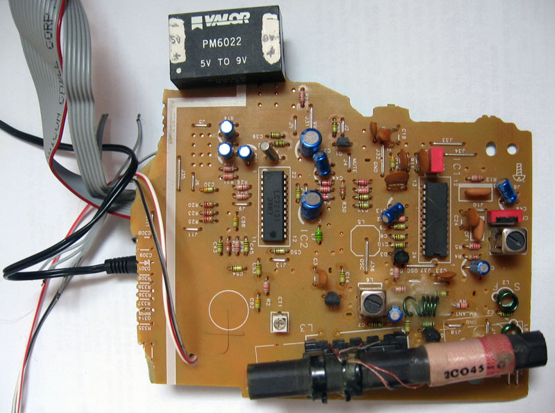
I immediately found out from the Internet that TA2008 is an AM / FM tuner (radio frequency amplifier, local oscillator, mixer, intermediate frequency amplifier), and LC72131 is a frequency synthesizer controlled by a microcontroller for a local oscillator. That is, the frequency at which the radio is tuned is determined by the data that the microcontroller writes to the chatota synthesizer. I have long dreamed of building some kind of receiver with a digital frequency setting, so I became interested and continued to search for information. I found the service manual for the RX-ES20 radio, where there was a circuit diagram, downloaded datasheets on TA2008 and LC72131, and began to understand how it all works.
The radio path of the RX-ES20 is the simplest - it can only work on CB ( AM MW 522.16.16 kHz , 9 kHz tuning step) and on VHF( FM 87.5..108 MHz , tuning step 50 kHz). The LC72131 synthesizer turned out to be very advanced, and in order to understand its operating principle, I had to completely translate the datasheet.
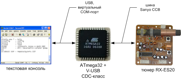
To control the radio path from the microcontroller, it is required to exchange data with the LC72131 via the 4-wire interface with the signals PLLDO, PLLDA, PLLCLK, PLLCE ( CCB Sanyo bus ), as well as set the signal T_MUTE (if it is in log. 1, then the radio path is turned off). Searching for ready-made routines for controlling the LC72131 led me to an interesting project of the amateur radio receiver P-45 (see the links below), from where I borrowed the routines for recording the synthesizer (the ATmega8 microcontroller was used in the P-45, and I had ATmega32but these were trifles). There were no routines for reading the synthesizer (the DO synthesizer leg was not used), I added it.
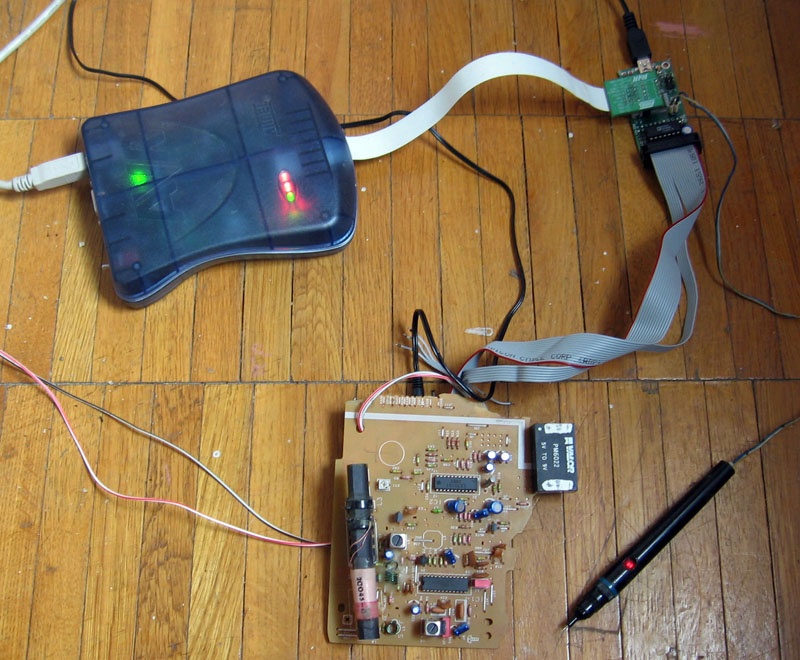
The radio path decided to connect to the AVR-USB-MEGA16 breadboard on which the ATmega32 microcontroller was installed. I provided for the possibility of controlling the receiver via USB - a simple text input of commands and text output to the console via a virtual USB COM port (using the V-USB library and the CDC USB class), so I did not need to write a program for the computer. The source code for the CDC-232 project was Osamu Tamura (the project is based on V-USB , see links).
VALOR DC-DC converter (to get 9 from 5 volts), a cable from an old ATA-hard drive, a headphone cord and a jack (jack) from an audio card came in handy from other rubbish. The cable and socket were soldered by a canopy to the board tracks. The project is in the process of debugging: The
radio
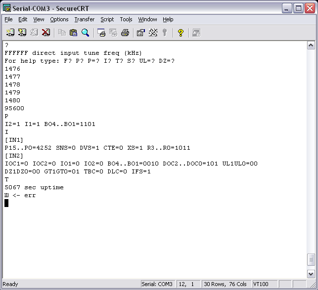
path is controlled by the following commands: FFFFFF direct input of the receive frequency in kHz (here the F characters mean frequency digits)
up arrow to increase the receive frequency per tuning step (in AM mode, I made 1 kHz step, in FM mode 25 kHz step)
down arrow decrease reception frequency per tuning step
F measure and show the local oscillator tuning frequency, the radio frequency reception frequency
P = bbbbset the state of the output ports BO4..BO1 of the LC72131 synthesizer chip (the b symbol means 0 or 1, the status of the corresponding BOx output).
P read and show the status of ports IO2, IO1 (inputs), BO4..BO1 (outputs) of the LC72131
I synthesizer chip show detailed information. The contents of all the internal flags of the LC72131 synthesizer chip, the synthesizer frequency division coefficient, are displayed.
? command prompt
When stereo reception is in progress (FM band), the red LED on the breadboard lights up. The synthesizer can be tuned in the range of 0.5 ... 160 MHz, but in reality, reception is only on SV and VHF (since the radio path to other ranges is not designed).
Screenshot of the radio control console:
If anyone is interested in boring technical details - welcome to the Links.
[ Links ]
1 . Translation of datasheet LC72131 .
2 . Detailed project description, firmware for radio control of the receiver on the ATmega32 . You can download the sources from the link (project for AVR Studio), the circuit diagram of the RX-ES20 radio, photos.
3 . P-45 - amateur radio scanning receiver 45..855 MHz.
4 . The CDC-Osamu the AVR Tamura @ Recursion Co .
Recently, at work, I came across the guts from the radio RX-ES20. Someone dismantled the case in a barbaric way, broke the electronics with meat and threw it away. I managed to save a piece from the board on which was the radio path of the radio, assembled on TA2008 and LC72131 chips .
I immediately found out from the Internet that TA2008 is an AM / FM tuner (radio frequency amplifier, local oscillator, mixer, intermediate frequency amplifier), and LC72131 is a frequency synthesizer controlled by a microcontroller for a local oscillator. That is, the frequency at which the radio is tuned is determined by the data that the microcontroller writes to the chatota synthesizer. I have long dreamed of building some kind of receiver with a digital frequency setting, so I became interested and continued to search for information. I found the service manual for the RX-ES20 radio, where there was a circuit diagram, downloaded datasheets on TA2008 and LC72131, and began to understand how it all works.
The radio path of the RX-ES20 is the simplest - it can only work on CB ( AM MW 522.16.16 kHz , 9 kHz tuning step) and on VHF( FM 87.5..108 MHz , tuning step 50 kHz). The LC72131 synthesizer turned out to be very advanced, and in order to understand its operating principle, I had to completely translate the datasheet.
To control the radio path from the microcontroller, it is required to exchange data with the LC72131 via the 4-wire interface with the signals PLLDO, PLLDA, PLLCLK, PLLCE ( CCB Sanyo bus ), as well as set the signal T_MUTE (if it is in log. 1, then the radio path is turned off). Searching for ready-made routines for controlling the LC72131 led me to an interesting project of the amateur radio receiver P-45 (see the links below), from where I borrowed the routines for recording the synthesizer (the ATmega8 microcontroller was used in the P-45, and I had ATmega32but these were trifles). There were no routines for reading the synthesizer (the DO synthesizer leg was not used), I added it.
The radio path decided to connect to the AVR-USB-MEGA16 breadboard on which the ATmega32 microcontroller was installed. I provided for the possibility of controlling the receiver via USB - a simple text input of commands and text output to the console via a virtual USB COM port (using the V-USB library and the CDC USB class), so I did not need to write a program for the computer. The source code for the CDC-232 project was Osamu Tamura (the project is based on V-USB , see links).
VALOR DC-DC converter (to get 9 from 5 volts), a cable from an old ATA-hard drive, a headphone cord and a jack (jack) from an audio card came in handy from other rubbish. The cable and socket were soldered by a canopy to the board tracks. The project is in the process of debugging: The
radio
path is controlled by the following commands: FFFFFF direct input of the receive frequency in kHz (here the F characters mean frequency digits)
up arrow to increase the receive frequency per tuning step (in AM mode, I made 1 kHz step, in FM mode 25 kHz step)
down arrow decrease reception frequency per tuning step
F measure and show the local oscillator tuning frequency, the radio frequency reception frequency
P = bbbbset the state of the output ports BO4..BO1 of the LC72131 synthesizer chip (the b symbol means 0 or 1, the status of the corresponding BOx output).
P read and show the status of ports IO2, IO1 (inputs), BO4..BO1 (outputs) of the LC72131
I synthesizer chip show detailed information. The contents of all the internal flags of the LC72131 synthesizer chip, the synthesizer frequency division coefficient, are displayed.
? command prompt
When stereo reception is in progress (FM band), the red LED on the breadboard lights up. The synthesizer can be tuned in the range of 0.5 ... 160 MHz, but in reality, reception is only on SV and VHF (since the radio path to other ranges is not designed).
Screenshot of the radio control console:
If anyone is interested in boring technical details - welcome to the Links.
[ Links ]
1 . Translation of datasheet LC72131 .
2 . Detailed project description, firmware for radio control of the receiver on the ATmega32 . You can download the sources from the link (project for AVR Studio), the circuit diagram of the RX-ES20 radio, photos.
3 . P-45 - amateur radio scanning receiver 45..855 MHz.
4 . The CDC-Osamu the AVR Tamura @ Recursion Co .