A Custom Way to Make Friends with STM32: Not Arduino or Discovery
To everyone who uses or is interested in microcontrollers from STMicroelectronics , I want to present my small hobby project.
Both Habré and geektimes already have a lot of articles devoted to microcontrollers of the STM32F series, for example: Cheap STM32 board + Arduino IDE , Trying to make friends with STM32 and the answer to it How to make friends with STM32 and many others. Together, they cover this topic very well, but there is one thing ... But in all these articles, ready-made boards and one specific controller that are on this board are considered. And what about those who want to play with different controllers, and even on the breadboard? For example, many boards I know of with the STM32F4 controller (the same STM32F4-Discovery) cannot be inserted into the breadboard. But I personally want something like this (attention, all pictures are clickable):

At the same time, as I already wrote, I do not want to be connected to a specific controller, but I want to be able to easily replace it. Those who are interested in how I realized these not quite ordinary Wishlist, I ask for a cat.
Использовать или нет макетные платы с разъемами — это вопрос достаточно спорный. Конечно, начиная с какого-то количества компонент, они становятся неудобными. Но пока компонент не очень много, а количество экпериментов на начальной стадии прототипирования еще велико, макетные платы, на мой взгляд, удобны. И вот тут, если хочется использовать STM32, нас поджидает засада — их просто нет в DIP корпусах, в отличиет от той же Atmega. Можно покупать готовые демо-платы, но тут опять засада — большинство таких плат со старшими контроллерами нельзя воткнуть в макетку из-за сдвоенных гребенок. То есть, используя готовые демо-платы, мы вынуждены работать с младшими контроллерами серии (см. то же Nucleo в DIP-варианте или Blue Pill). Второй путь — делать специализированние адаптеры. В данной статье этот второй путь и рассматривается.
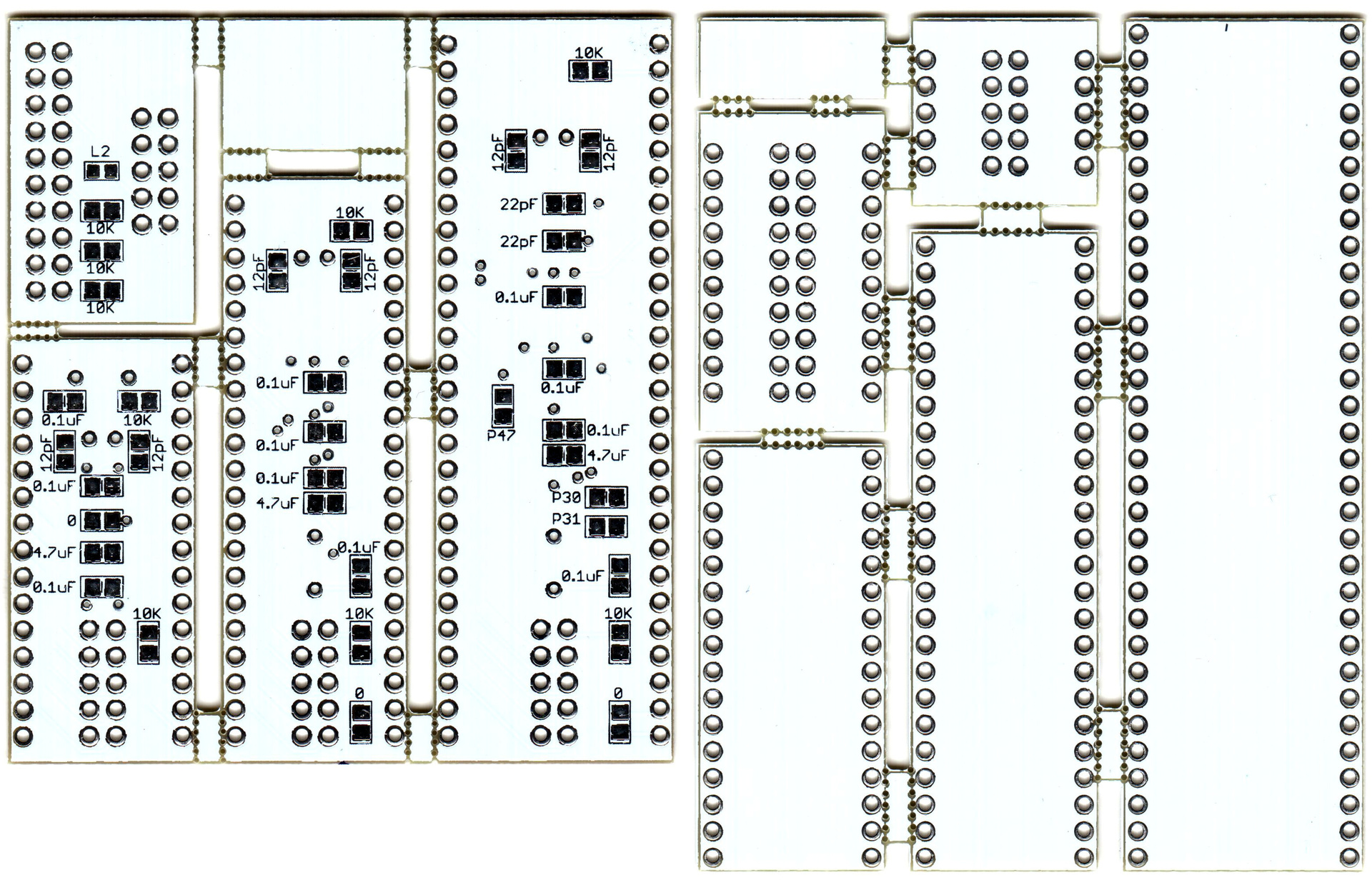
Immediately show the final result. These are small double-sided scarves for different cases, the printing of which can be ordered in the Middle Kingdom (the Chinese have nothing against printing double-sided boards with a panel design):
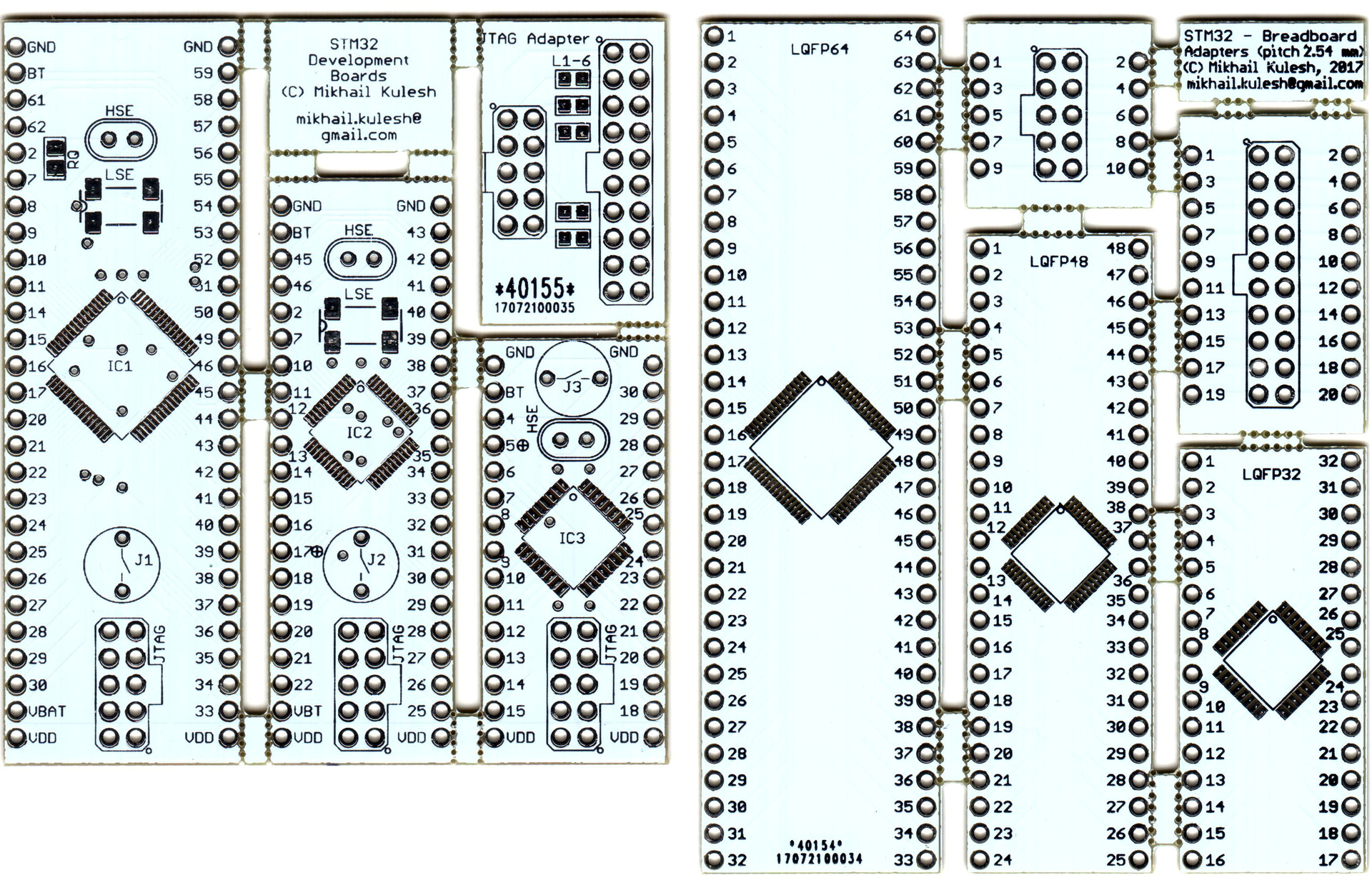
One set (on the right) is simply plain adapters for the breadboard for LQFP32 / 48/64 cases, but the second set (on the left) are also adapters, but with a JTAG connector, power, low-frequency and high-frequency quartz and a reset button. All other controller pins are on the comb. In general, the very minimum. Unfortunately, the JTAG connector is not standard, so the adapter board from JTAG-20 to this same JTAG-10 is also included.
These boards are easily soldered by a hairdryer at home, so if you have several controllers, several boards and passive components of size 0805, you can get something like this in a reasonable amount of time:
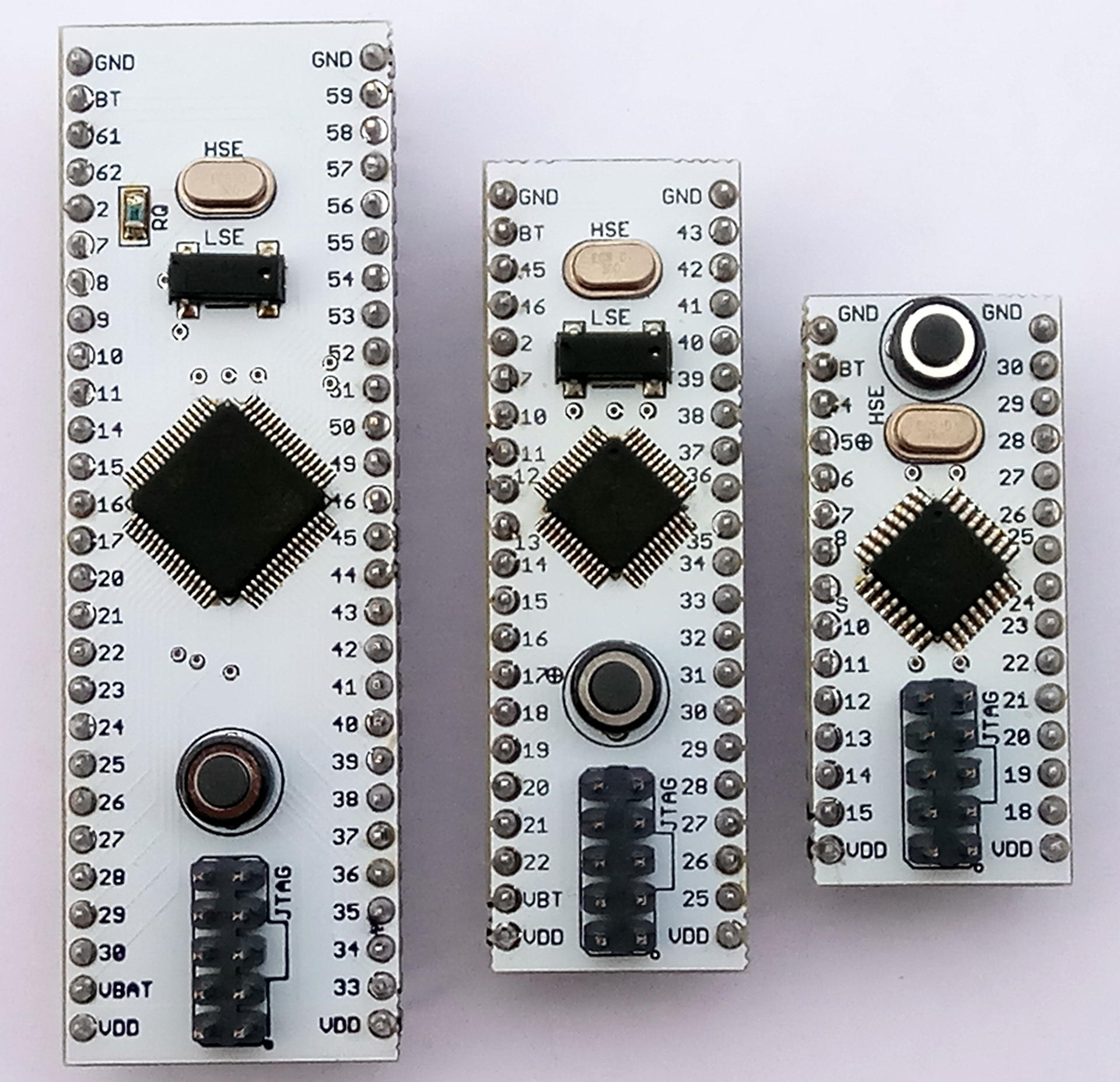
And this, it seems to me, gives a good freedom of creativity. If someone seems to have exhausted the topic, then here is a link to the github repository .
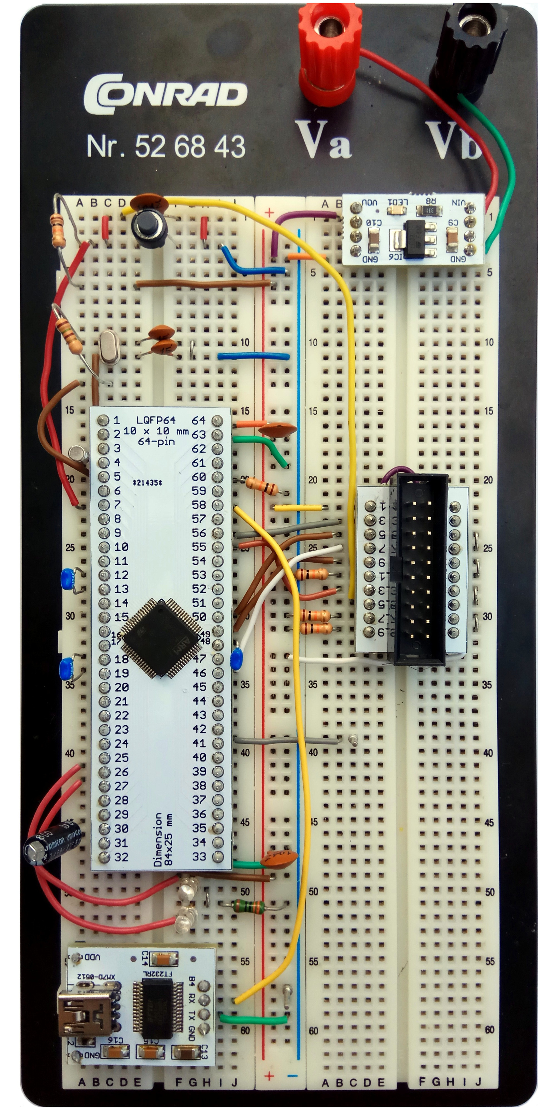
But I want to further tell you step by step how to get to such a life. A picture to attract attention (graphic statement of the problem):
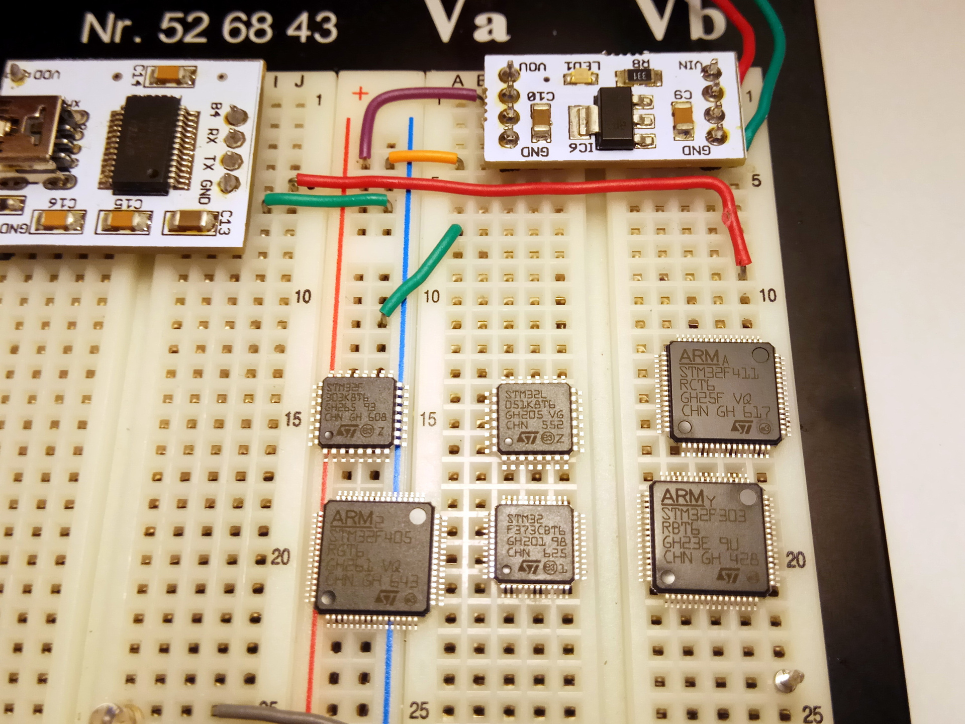
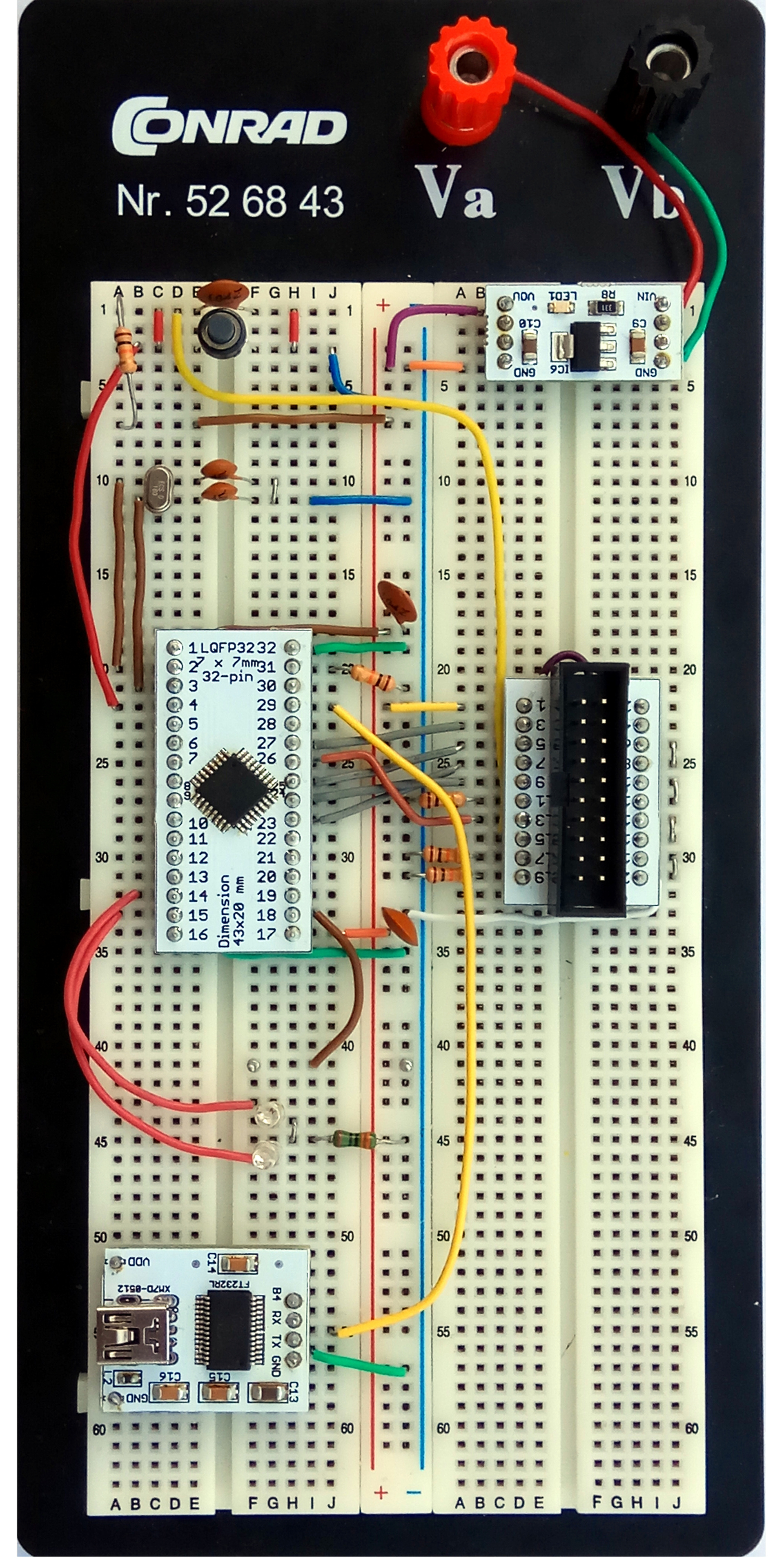
There is a scattering of controllers (L0, F3, F4 series), power, USART-USB converter, breadboard. I want to blink the LEDs. This step is made very easy. We take any controller, adapter card from the first set, we solder a hairdryer. Next, you need documentation on connecting the power, programmer, quartz. Here ST has a complete order, everything is on the page with the documentation of the selected controller. For example, for STM32F303K8 we need only one document: AN4206: Getting started with STM32F3 series hardware development , where there are power supply circuits, oscillators and a programmer, based on which you can build such a model:
This controller does not have an external low-frequency quartz, so I connected only high-frequency at 16 MHz. For programming, a standard JTAG-20 connector is used, which is equipped with a standard programmer from ST ST-LINK / V2 .
Драйвера уже есть в ядре, но необходимо вручную добавить несколько правил в файл /etc/udev/rules.d, см. Например, тут
Since the article is devoted more to the hardware part, I will only briefly mention the software part. Operating system: Fedora 25. Development environment: System Workbench for STM32 is a completely free system based on Eclipse from OpenSTM32 Community. The only time - to download, you must register on the site http://www.openstm32.org . It is convenient to use the graphical utility STM32CubeMX for modeling, documenting and generating examples . For example, the controller configuration in the photo above looks like this:
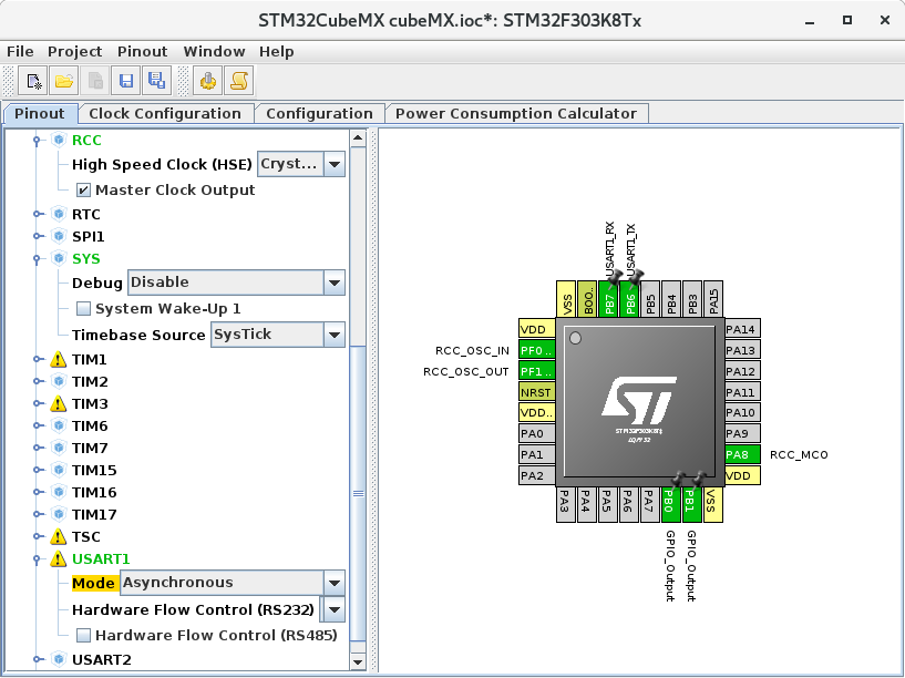
Files with these schemes are also in the repository. For example, for STM32F303K8 see here
System Workbench for STM32 has a built-in, fairly advanced project wizard, which generates the initial project structure, and can optionally include in the project: low-level controller drivers (CMSIS), HAL library (Hardware Abstraction Layer), FatFS, FreeRTOS. I myself use my object-oriented driver library, which runs on top of the HAL. Who cares, see here .
Here is an example of a code using this library, which blinks LEDs on a timer (on an interrupt) and logs (via a USART-USB converter to the workstation console) the status of the counter connected to the real-time clock. All this is somewhat similar to Arduino's ideology, but I just like to program such things myself.
Here is an example of using a fairly powerful STM32F410RB controller :
Similarly, the main document is AN4488: Getting started with STM32F4xxxx MCU hardware development , where there are all the necessary connection schemes. The second important document is AN2867: Oscillator design guide for STM8AF / AL / S and STM32 microcontrollers , which details how to connect a high-frequency oscillator.
Naturally, constantly fencing such schemes is rather time-consuming, so I decided to make the next possible universal scarves, which will realize these schemes. Versatility is achieved due to the fact that the controllers of different series, but in the same case (for example, STM32F303RB and STM32F410RB, both in the LQFP64 case) have the same conclusions (with the exception of small differences in the power supply circuit). These differences lead to this:
All elements with signed values are common to different controllers, but elements like P30, P31, P47, where the number means the pin number, must be selected depending on the specific model. As a result, the breadboard will look like this:
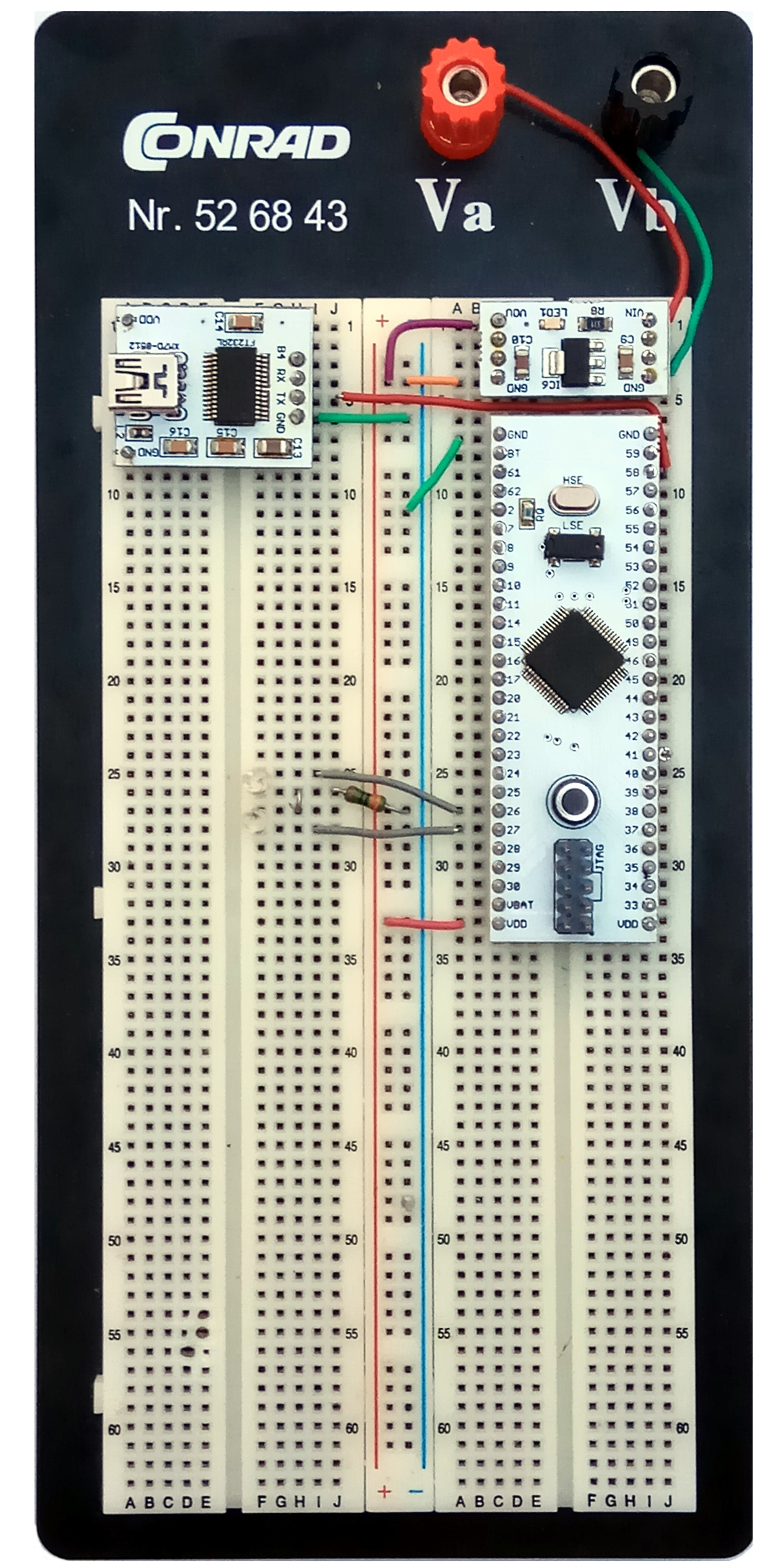
Here is such a small improvement.
→ github Project
License: GNU General Public License, Version 3
Schematic and circuit board prepared by Eagle Cad. The immensely respected DiHalt has a wonderful series of articles on this system . The free version of Eagle Cad for home use can be downloaded from the official website .
I invite everyone to join the project.