Programming PIC16 / PIC18 microcontrollers in C language. Article two. Basic platform information. First program
If everything worked out well in the first article, we got a basic programming environment for continuing education.
We are going further.
As I said earlier, for now I will explain on the basis of MK PIC16F628A .
Be sure to download the documentation for it. I recommend for search - alldatasheet.com
DataSheet - the main document in the development based on MK.
I recommend printing the main tables and sections for ease of use.
Open LH.
The most important information about the crystal:
- maximum operating frequency - 20 MHz;
- 2048x14 bit flash ROM;
- 224 bytes of static RAM;
- 128 bytes of non-volatile ROM;
- 16 available conclusions;
- transceiver module;
- 3 timers.
This crystal is a representative of the so-called Mid-range MK PIC family.
I’ll briefly talk about what you need to understand .
The device data memory is divided into 4 banks .
Banks contain special purpose registers (SFR) and general purpose registers (GPR).
SFR - used to control the device and its modules.
General purpose registers are presented in the form of static RAM, where we can store our variables.
Special registers occupy 32 initial positions in each bank.
In LH, pages 18-21 show all special purpose registers. Print them - it will come in handy more than once.
This is a rather voluminous topic, and it is impossible to miss it.
But on the other hand, boring and uninteresting.
Try to overpower yourself and read about the organization of memory and special-purpose registers in the school and at Shpak (mentioned in the first article).
I / O ports .
This device has two ports: PORTA and PORTB.
Each port pin can be used directly as a simple pin or as a pin from other MK modules.
At the very beginning of the DS you should have noticed that each conclusion, in addition to the main name, for example RB1, also contains another name RX and DT.
Here RX is a secondary output function - as an input of a transceiver.
But for now, we will not touch the peripheral modules of the device.
Each port pin can function as an input or as an output.
For example, if we need to light an LED, then the output to which it is connected, we configure as an output, and set the appropriate level on it.
But if we need to connect the button to the port and read the fact of pressing, then here it is already necessary to configure this output as an input.
Input / output configuration is done using TRIS registers .
If 1 is written in the corresponding bit of the TRIS register, then this output will become an input, if 0 - an output (apparently due to the similarity of 1 and Input, and 0 and Output)
For example:
The names of the registers can be found in the folder “HT-PICC \ include folder” for the corresponding controller.
To establish a certain level on the output, use the PORT register.
For example:
So. We reach the point where it is necessary to make a digression in the C language itself.
I will probably write a small example here. Compile. Run in Proteus, and I will write about the base language C in the next article.
Let's write a small program. We blink an LED.
We use the previously created project, or create a new one, according to the scheme from the first article.
To get started, we’ll include a header file.
We do not select a specific model, but specify pic.h. If you open it, we will see a script for selecting a specific file based on the selected device when creating the project.
Next we need to initialize our ports.
We create the main function of the program:
We write at its beginning:
Let's go to the HT-PICC \ samples \ delay folder.
Copy delay.c and delay.h from there and paste them into the project folder.
Add a line at the beginning:
#include “delay.c”
We will use the DelayMs (x) function to create a pause between LED switching.
Let's say the LED is connected to RB0.
A logical exclusive “OR” will be used to switch it:
As a result, the code takes the form:
The firmware is ready.
Now configure the configuration bits.
Click Configure -> Configuration bits .
We remove the “Configuration Bits set in code” checkbox , since we did not set anything in the code.
We see a few points.
We expose as on the screen.
Oscillator - HS - A high-frequency quartz resonator will be used as a clock generator.
WatchDog Timer - Off, if enabled, the microcontroller will be periodically reset to avoid any freezes. We do not need such an opportunity yet .
Power up timer- Enabled, the MC will be in a reset state until the supply voltage reaches the required threshold level.
Brown Out Detect - On, resetting the MC if there is a drop in the supply voltage below a certain level.
Low Voltage Program - Disabled, prohibit the use of low-voltage in-circuit programming MK. It already depends on your programmer.
Data EE Read Protect - Off, allow reading data and EEPROM memory MK.
Code Protect - Off, disable code protection in MK. If you set On, then it will be impossible to read the program from MK. Us until such a possibility is not needed.

Press F10 again.
We close.
Run the program in Proteus.
Launch Proteus ISIS.
In the Component mode section, click Pick from libraries and, using the search, add the components to the form:
- PIC16F628A;
- LED-RED;
- RES;
Double-click on each of them and set the parameters.
For MK - select the * .hex firmware file from our project folder, and set the frequency to 4 MHz.
For LED-RED, select Model type - Digital.
For the resistor, select a resistance of 300 ohms.
Add to the Ground form in the Terminals mode section and connect as on the screen.

Click Play - the LED should blink.
The next article will cover the C language.
Following it will be an article on the periphery of the controller and code samples for it.
And behind it I plan to talk about USB and PIC 18.
Here's a plan for now :-)
We are going further.
As I said earlier, for now I will explain on the basis of MK PIC16F628A .
Be sure to download the documentation for it. I recommend for search - alldatasheet.com
DataSheet - the main document in the development based on MK.
I recommend printing the main tables and sections for ease of use.
Open LH.
The most important information about the crystal:
- maximum operating frequency - 20 MHz;
- 2048x14 bit flash ROM;
- 224 bytes of static RAM;
- 128 bytes of non-volatile ROM;
- 16 available conclusions;
- transceiver module;
- 3 timers.
This crystal is a representative of the so-called Mid-range MK PIC family.
I’ll briefly talk about what you need to understand .
The device data memory is divided into 4 banks .
Banks contain special purpose registers (SFR) and general purpose registers (GPR).
SFR - used to control the device and its modules.
General purpose registers are presented in the form of static RAM, where we can store our variables.
Special registers occupy 32 initial positions in each bank.
In LH, pages 18-21 show all special purpose registers. Print them - it will come in handy more than once.
This is a rather voluminous topic, and it is impossible to miss it.
But on the other hand, boring and uninteresting.
Try to overpower yourself and read about the organization of memory and special-purpose registers in the school and at Shpak (mentioned in the first article).
I / O ports .
This device has two ports: PORTA and PORTB.
Each port pin can be used directly as a simple pin or as a pin from other MK modules.
At the very beginning of the DS you should have noticed that each conclusion, in addition to the main name, for example RB1, also contains another name RX and DT.
Here RX is a secondary output function - as an input of a transceiver.
But for now, we will not touch the peripheral modules of the device.
Each port pin can function as an input or as an output.
For example, if we need to light an LED, then the output to which it is connected, we configure as an output, and set the appropriate level on it.
But if we need to connect the button to the port and read the fact of pressing, then here it is already necessary to configure this output as an input.
Input / output configuration is done using TRIS registers .
If 1 is written in the corresponding bit of the TRIS register, then this output will become an input, if 0 - an output (apparently due to the similarity of 1 and Input, and 0 and Output)
For example:
TRISA = 0; // Все выводы порта А - выходы

TRISB = 0xff; // Все выводы порта B - входы

TRISA5 = 1; // 5 вывод порта А - вход. Кстати не у всех компиляторов можно обращаться к каждому выводу непосредственно
The names of the registers can be found in the folder “HT-PICC \ include folder” for the corresponding controller.
To establish a certain level on the output, use the PORT register.
For example:
PORTA = 0; // Все выводы порта А с низким уровнем

PORTB = 0xff; // Все выводы порта B с высоким уровнем

RB5 = 1; // На пятом выводе порта B высокий уровень
So. We reach the point where it is necessary to make a digression in the C language itself.
I will probably write a small example here. Compile. Run in Proteus, and I will write about the base language C in the next article.
Let's write a small program. We blink an LED.
We use the previously created project, or create a new one, according to the scheme from the first article.
To get started, we’ll include a header file.
#include We do not select a specific model, but specify pic.h. If you open it, we will see a script for selecting a specific file based on the selected device when creating the project.
Next we need to initialize our ports.
We create the main function of the program:
 void main(void)

{

 while(1);

}
We write at its beginning:
 TRISA = 0; // Порт А - все выводы выходы

 PORTA = 0; // с логическим нулем

 TRISB = 0; // Порт B - все выводы выходы

 PORTB = 0; // С логическим нулем
Let's go to the HT-PICC \ samples \ delay folder.
Copy delay.c and delay.h from there and paste them into the project folder.
Add a line at the beginning:
#include “delay.c”
We will use the DelayMs (x) function to create a pause between LED switching.
Let's say the LED is connected to RB0.
A logical exclusive “OR” will be used to switch it:
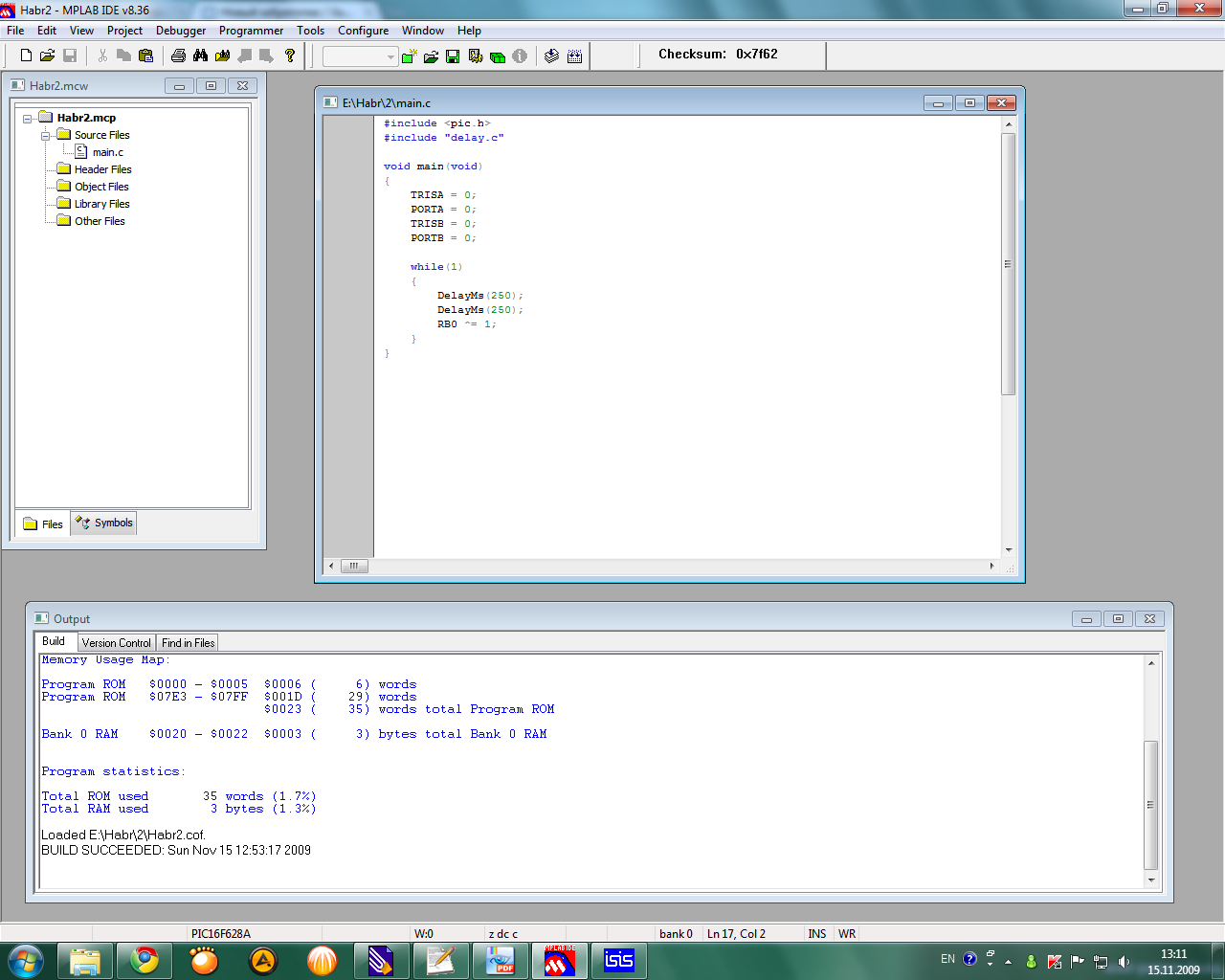
RB0 ^= 1;As a result, the code takes the form:
#include

#include "delay.c"


void main(void)

{

 TRISA = 0;

 PORTA = 0;

 TRISB = 0;

 PORTB = 0;


 while(1)

 {

 DelayMs(250); // Сделаем паузу в полсекунды

 DelayMs(250);

 RB0 ^= 1; // инвертируем вывод

 }

}
The firmware is ready.
Now configure the configuration bits.
Click Configure -> Configuration bits .
We remove the “Configuration Bits set in code” checkbox , since we did not set anything in the code.
We see a few points.
We expose as on the screen.
Oscillator - HS - A high-frequency quartz resonator will be used as a clock generator.
WatchDog Timer - Off, if enabled, the microcontroller will be periodically reset to avoid any freezes. We do not need such an opportunity yet .
Power up timer- Enabled, the MC will be in a reset state until the supply voltage reaches the required threshold level.
Brown Out Detect - On, resetting the MC if there is a drop in the supply voltage below a certain level.
Low Voltage Program - Disabled, prohibit the use of low-voltage in-circuit programming MK. It already depends on your programmer.
Data EE Read Protect - Off, allow reading data and EEPROM memory MK.
Code Protect - Off, disable code protection in MK. If you set On, then it will be impossible to read the program from MK. Us until such a possibility is not needed.
Press F10 again.
We close.
Run the program in Proteus.
Launch Proteus ISIS.
In the Component mode section, click Pick from libraries and, using the search, add the components to the form:
- PIC16F628A;
- LED-RED;
- RES;
Double-click on each of them and set the parameters.
For MK - select the * .hex firmware file from our project folder, and set the frequency to 4 MHz.
For LED-RED, select Model type - Digital.
For the resistor, select a resistance of 300 ohms.
Add to the Ground form in the Terminals mode section and connect as on the screen.
Click Play - the LED should blink.
The next article will cover the C language.
Following it will be an article on the periphery of the controller and code samples for it.
And behind it I plan to talk about USB and PIC 18.
Here's a plan for now :-)