How to make a very noticeable informer of the LED module for outdoor advertising and Arduino
- Tutorial
How to make a very noticeable informer of the LED module P10 and Arduino.
Purpose : Quickly connect a large P10 LED matrix (16x32cm) to a PC or other device, turning it all into a very noticeable and bright informer with a dynamic change of output information. The applications of such a thing can be found in mass and, as practice shows, it is very attractive.Just imagine, now everyone will know for sure that the air conditioner is working and it is supposed to close the door!

Illumination is not from the window, but from the panel;)
Once I looked at the dull matrix of 8x8 LEDs for Arduino and I was sad for their cost. It was decided to drop in the direction of ready-made running lines for outdoor advertising and what was my surprise when they all turned out to be standard and all as one did not know anything about the dynamic update of information through an external port. Having dug deeper, it was found that typical LED modules (LED arrays) are used in all such products.
Everyone has seen bright outdoor advertising screens from simple crawl lines to huge TVs. These screens are assembled from a chain of such LED modules and are controlled by special controllers, the price of which increases in direct proportion to the size of the screen.
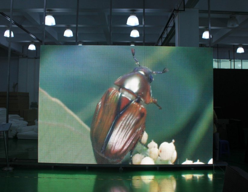
These LED modules are pretty cheap. About $ 6, the price depends on the size and color. With controllers harder. The simplest ones for the price are comparable with a single LED panel. However, most of them are "sharpened" to work in the demonstration mode of pre-prepared "presentations" and do not have the ability to dynamically change the output information. I admit that I only briefly familiarized myself with the functionality of the simplest controllers, but this turned out to be enough to understand that it was cheaper and faster to do what was needed on the universal Arduino controller. This will allow you to connect quite quietly several modules. But we will start with one.
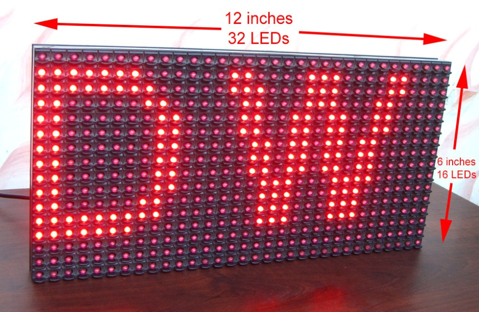
The LED module (P10) looks like this:
http://digital-wizard.net/avr_projects/p10_led_display_panel_interface
In fact, this is just a matrix of LEDs that are soldered to the outputs of the shift registers, we will not go into the jungle of circuitry, the modules are all standard and differ only in size. P10 means that between two neighboring diodes 10mm. There are monochrome, two-color and even RGB panels. For those interested in the details there is already a similar article, but with a bias to a lower level.
Hardware
And for those who want to quickly get a result that you can “touch”, you will need:
- One LED matrix.
- Arduino. (I used mini, but it will be more convenient for nano not to use additional adapters for communication with a PC).
- Power supply 5V / 3A. The matrix is gluttonous, if you light up all the diodes then you need a lot of power.
- Connection cable. (Usually it comes with a matrix.)
- The desire to finish the job.
We will do a monolithic construction that you just need to plug into the outlet and the PC to display our precious information (eg bitcoin rate).
It is necessary to take the cable from the matrix, cutting it in half to solder in a simple pattern to the Arduino.
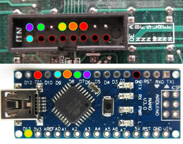
If you use the Arduino Mini or UNO, then you need to solder to the corresponding pins by analogy.
If for some reason you didn’t have a loop, you can replace it with a MIDI cable which in old sound cards connects to the MIDI connector itself (option for the old-timer) or replace with two Dupont plugs (mother) with 8 pins. In principle, the standard connector is searched quite easily.
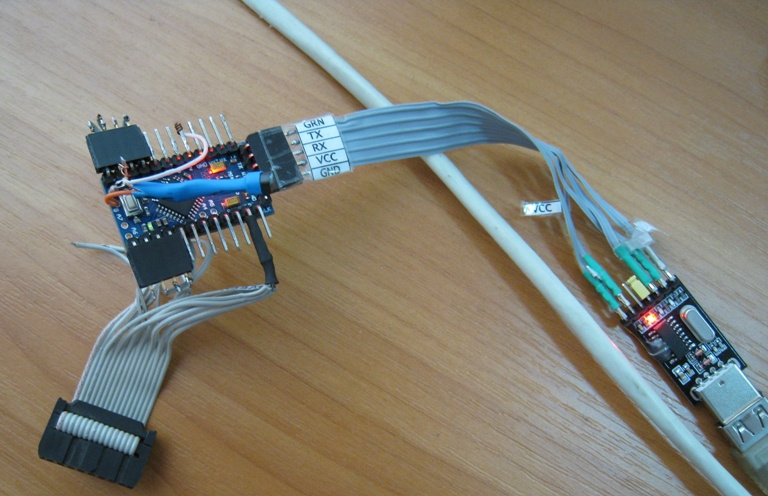
In 10 minutes I got the following design, I still have an additional USBtoUART adapter, which you will not have if not using the Arduino Mini.
The hardware is ready, you only need to connect an additional 5V / 3A power supply unit to power the matrix. To do this, it has a separate connector, plus a plus, minus to minus. On the contrary it is possible, but it will not work.Although it is strange, since everyone knows that electrons, as usual, flow from plus to minus. And if we take into account that electrons are negatively charged, it is not at all clear why they flow to the negative pole ...;) Nonsense were shorter.

I hope that you connect the power more reliably, and my method is great only if you have a lot of spare power supplies. Arduin can be bolted (not a self-tapping screw!) to the panel itself, there are mounting threaded holes in the panel.
That's all, may the gods forgive me for DIY, but today there were no blue electrical tape. It is not good to spend such a valuable resource on such worthless things.
Software part
If you thought you would need to figure out how to program this three-letter thing (SPI interface), then I might disappoint you - everything is much simpler. As always, all the bikes invented before us and more than once.Actually like this article. There are ready-made libraries DMD and DMD2 and drawing boils down to the fact that in the sketch you just need to specify what, how and where to output, all - Profit!
Having played a little with the square shape of these libraries, I came to the conclusion that scrolling of the text in DMD2 looks “sad”, although there are more features and brightness control. As a result, I stopped at the first and remembering that "you are a programmer," added a primitive brightness control to it. Here it is worth mentioning that these matrices shine very brightly. By the end of debugging, the cornea will be burned out.
In general, all you need to do is upload the sketch to the board, but from the directory where you unpack my archive, since I have modified it a bit by filesome libraries that are there too. Brightness control was added and SPI was a little bit overclocked, maybe I don’t even remember.Rabatet? Do not touch!
For greater clarity, I added a 18v20 temperature sensor. If you do not connect this, then the temperature will simply not be displayed. My idea is that there will be displayed a certain weight in grams, but you can display just a number. To change the text that is scrolled from below you just need to load it into the COM port of the Arduino using a special format, some kind of ESC sequence. Attached is a Python script that simply sends the current time to the panel.
Control command format:
- 0x1B (ESC) + 0x40 ("@") // Identification, returns the device ID string "P10_DISPLAY_V01 \ r \ n"
- 0xOC (CLR) // Screen Cleaning.
- 0x1F (US) + 0x58 (“X”) + 0x80 // Set the screen brightness, 0x80 maximum brightness.
- 0x1F (US) + 0x52 ("B") + Line // Set the bottom line to scroll.
- 0x1F (US) + 0x0A ("LF") + 0x31, 0x32, 0x33, 0x34, 0x35 // Transfer the five-digit number displayed at the top to "12345"
I did not find the finished one and had to draw a Russian font 5 * 7. Likely a bicycle, but unless we always do everything rationally?
Sketch:
//====================== OneWire ====================================#include<OneWire.h>OneWire ds2(2);
String res = "";
byte type_s;
byte data[12];
byte addr_ds2[8];
bool temp_sensor_2_found = false;
float temp1 = 999;
//===================================================================#include<SPI.h>        #include"DMD.h"#include"TimerOne.h"#include"SystemFont5x7rus.h"#define CLR 0x0C#define US 0x1F#define ESC 0x1B#define LF 0x0Astaticconstchar ID[] = "P10_DISPLAY_V01\r\n";    // Device ID#define DISPLAYS_ACROSS 1#define DISPLAYS_DOWN 1DMD dmd(DISPLAYS_ACROSS, DISPLAYS_DOWN); // Конфигурация экрана, панелей может быть не одна.#define max_char1 6#define max_char2 176unsignedchar message1[max_char1] = {0x20,0x30,0x30,0x30,0x30,0x00};    // stores you messageunsignedchar message2[max_char2];    // stores you messageunsignedchar r_char;
byte index1 = 4;
byte index2 = 176;
int i;
long scrollSpeed = 25;
char test[] = { 0x84,0x80,0x20,0x87,0x84,0x90,0x80,0x82,0x91,0x92,0x82,0x93,0x85,0x92,0x20,0x92,
                0x8E,0x20,0x81,0x8B,0x80,0x83,0x8E,0x84,0x80,0x90,0x9F,0x20,0x97,0x85,0x8C,0x93,
                0x20,0x8C,0x9B,0x20,0x8D,0x85,0x91,0x8C,0x8E,0x92,0x90,0x9F,0x20,0x8D,0x88,0x20,
                0x8D,0x80,0x20,0x97,0x92,0x8E,0x20,0x88,0x20,0x82,0x8E,0x8F,0x90,0x85,0x8A,0x88,
                0x20,0x82,0x91,0x85,0x8C,0x93,0x21,0x00};
//=============================================================================boolget_sensor(byte addr[8], OneWire ds){
  // Ищем адрес датчикаif  (! ds.search  (addr)) {
    ds.reset_search  ();
    delay  (250);
    returnfalse;
  }
  // Проверяем не было ли помех при передачеif (OneWire::crc8(addr, 7) != addr[7])
  {
    Serial.println("get_sensor:CRC is not valid!");
    returnfalse;
  }
  // Определяем серию датчикаswitch (addr[0])
  {
    case0x10:
      //Chip = DS18S20
      type_s = 1;
      break;
    case0x28:
      //Chip = DS18B20
      type_s = 0;
      break;
    case0x22:
      //Chip = DS1822
      type_s = 0;
      break;
    default:
      Serial.println("get_sensor:Device is not a DS18x20 family device.");
      returnfalse;
  }
  returntrue;
}
//=============================================================================doubleget_temp(byte addr[8], OneWire ds){
  double celsius;
  ds.reset  ();
  ds.select  (addr);   // Выбираем адрес
  ds.write  (0x44, 1); // Производим замер, в режиме паразитного питания
  delay  (750);
  ds.reset  ();
  ds.select  (addr);
  ds.write  (0xBE); // Считываем оперативную память датчикаfor  (int i = 0; i < 9; i++) { // Заполняем массив считанными данными
    data[i] = ds.read  ();
  }
  // Данные о температуре содержатся в первых двух байтах, переведем их в одно значение и преобразуем в шестнадцатиразрядное числоint raw =  (data[1] << 8) | data[0];
  if  (type_s) {
    raw = raw << 3; // 9 bit resolution defaultif  (data[7] == 0x10) {
      raw =  (raw & 0xFFF0) + 12 - data[6];
    }
  }
  else
  {
    byte cfg =  (data[4] & 0x60);
    if  (cfg == 0x00) raw = raw << 3;
    elseif  (cfg == 0x20) raw = raw << 2;
    elseif  (cfg == 0x40) raw = raw << 1;
  }
  celsius =  (double)raw / 16.0;
  return celsius;
};
//=============================================================================voidmassage2BufClear(){
  for(i=0; i<max_char2; i++)
        {
            message2[i] = '\0';
        }
        index2=0;
}
//--------------------------------------------------------------voidmassage1BufClear(){
        message1[0] = 0x20;
        message1[1] = 0x30;
        message1[2] = 0x30;
        message1[3] = 0x30;
        message1[4] = 0x30;
        message1[5] = 0x00;
        index1=0;
}
//--------------------------------------------------------------voidmassage1Normalization(){
  char buf[5];
  buf[0] = 0x20;
  buf[1] = 0x30;
  buf[2] = 0x30;
  buf[3] = 0x30;
  buf[4] = 0x30;
  int char_count = index1;
   for(i = char_count - 1; i >= 0; i--)
   {
      buf[i] = message1[i];
   }
   massage1BufClear();
   for(i = char_count - 1; i >= 0; i--)
   {
      message1[i+5-char_count] = buf[i];
   }
}
//------------------------------------------------------------------voidScanDMD(){
  dmd.scanDisplayBySPI();
}
//------------------------------------------------------------------voidsetup(void){
   Timer1.initialize( 500 );
   Timer1.attachInterrupt( ScanDMD );
   dmd.clearScreen( true );
   Serial.begin(9600);
   strcpy(message2,test);
   dmd.brightness = 70;
   temp_sensor_2_found = get_sensor(addr_ds2, ds2);
   dmd.selectFont(SystemFont5x7);
}
//------------------------------------------------------------------voidloop(void){
   dmd.drawMarquee(message2 ,index2,(32*DISPLAYS_ACROSS)-1 ,8);
    if (temp_sensor_2_found)                  // !!!!!!!
    {                                         // !!!!!!!
     res = String(get_temp(addr_ds2, ds2));   // !!!!!!!
     res.toCharArray(message1, 5);            // !!!!!!!
     message1[4] = 0xF8;                      // !!!!!!!
    }                                         // !!!!!!!long start=millis();
   long timer=start;
   boolean ret=false;
   while(!ret)
   {
     if ((timer + scrollSpeed) < millis()) {
        dmd.drawFilledBox( 0,0,31,7, GRAPHICS_INVERSE);
        ret=dmd.stepMarquee(-1,0);
        timer=millis();
        dmd.drawString(  1,  0, message1, 5, GRAPHICS_NORMAL );
        if(Serial.available())
          break;
     }
   }
}
//-----------------------------------------------------------------------------------voidserialEvent(){
      delay(25); // Wait all data
      r_char = Serial.read();
      if(r_char < 0x20)
      {
          switch (r_char)
          {
              case ESC:
                r_char = Serial.read();
                if(r_char=='@')
                {
                  Serial.write(ID);
                }
                break;
              case CLR:
                massage1BufClear();
                massage2BufClear();
                break;
              case US:
                r_char = Serial.read();
                if(r_char=='X')
                {
                  dmd.brightness = Serial.read();
                }
                if(r_char=='B'){
                  massage2BufClear();
                  while(Serial.available() > 0)
                  {
                    r_char = Serial.read();
                    if(index2 < (max_char2-1))
                      {
                        if(r_char > 0x1F)
                        {
                            message2[index2] = r_char;
                            index2++;
                        }
                      }
                  }
                }
                  if(r_char==LF){
                          massage1BufClear();
                          while(Serial.available() > 0)
                                  {
                                    r_char = Serial.read();
                                    if(index1 < (max_char1-1))
                                      {
                                        if((r_char > 0x29) and (r_char < 0x3A))
                                        {
                                            message1[index1] = r_char;
                                            index1++;
                                        }
                                      }
                                  }
                          massage1Normalization();
                }
                dmd.drawFilledBox( 0,8,31,15, GRAPHICS_INVERSE);
                break;
              default:
                break;
            }
          }
   while (Serial.available()) Serial.read();
   dmd.writePixel(0,0,GRAPHICS_NORMAL,1);
}
Work at full brightness:
Work with human brightness:
Working with dynamic time loading from a PC using a Python script:
All the irregularities with scrolling due to shooting on the camera, for the eyes from a normal distance, everything looks quite smooth and readable.
It should be noted that quite freely you can connect several modules sequentially and just by specifying it in the sketch to get a larger screen. Restrictions begin only after a certain number of panels and they are related to the limited performance of the Arduino and its SPI interface. Thanks to ElectricFromUfa for a detailed and detailed overview of the panels and not only!
Perhaps in the future I will do the same thing on the STM32F103C8T6 and on the ESP-12F, everything should be moving faster there.
References:
1. Link to the archive with the sketch and accompanying.
2. Another link to BitBucket
http://conture.by/post/1100
http://ediy.com.my/blog/item/116-arduino-driving-a-32x16-dot-matrix-display-panel
http://blog.vettore.org/building-a-large-led-sign-with-inexpensive-standard-modules-and-arduino/
http://digital-wizard.net/avr_projects/p10_led_display_panel_interface
https://geektimes.ru/post/275548/
https://forum.arduino.cc/index.php?topic=260320.0
https://www.youtube.com/channel/UChButpZaL5kUUl_zTyIDFkQ