Smart home, as I sunk to such. Part 4
 In the first three parts, I described how I came up with the idea (necessity) of building a “smart home” and how I realized it.
 In this part, I will tell you what shortcomings were identified during the four years of operation of the system, and what other useful things could be implemented.
Well, a small spoiler: under the cut there will be a brief description of “the next crafts on esp8266 with preference and courtesans”.
So, four years have passed (since the beginning of the operation of the first modules, so generally six). In general, the system performed well, but two shortcomings surfaced, however, quite expected.
The first is centralization. Yes, this is bad, yes, I knew about it, but there was no experience in the production of end-user devices, and the 1-Wire protocol chosen as the main one did not provide such an opportunity.
Accordingly, the central server has become a bottleneck. Five times because of the failure of the “iron”, the whole system did not work for more than a day (or even two or three) and had to use the backup system (turn on the lighting in the switchboard, do without a heated floor, ventilation, recalibrate water meters, etc. d.)
Plus, there have been frequent power outages in the house for more than an hour. The UPS charge ended and the server made an emergency shutdown, and, more precisely, very rudely cut down. After that, its rise was not always smooth, mainly because MySQL does not like such a boorish attitude to itself. Restoring tables (and there the whole story on all sensors for many years) sometimes took hours and it was not always possible for him to do this without outside intervention. Yes, this problem, theoretically, can be solved by purchasing a smarter UPS, connecting it to the server and teaching the server to shut down regularly when power is lost. But my current UPS is still a vigorous old man, and the motherboard of the server, for some reason, did not want to work normally in the mode, automatically turning on after the power was turned on, if it had been permanently turned off.
The second is a restriction on the topology of the 1-Wire bus + my inexperience.
Yes, I read that there should be a central trunk and only small branches, about which it is written a lot. But the project was expanding quite unpredictably and at the same time everything seemed to work. And then, in one “wonderful” moment, it stopped working. That is, turn off some of the devices, everything is fine, turn on again and the signal starts to "float." Replaced some of the main lines with shielded ones, minimized the branches, but it is no longer possible to make a full-fledged single tire without a perforator and significant damage to the finish. As a result, I broke the network into two segments, brought it to two separate controllers, but, nevertheless, once in a couple of months the problem arose again when the devices started falling out of the network. Only the complete shutdown of the entire system with subsequent switching on helped, but this procedure is not very trivial and my homework cannot be carried out without me.
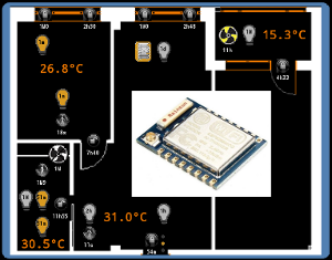
In the meantime, about two years ago, I came across an article and I had an idea to make a kind birthday present to my father. He is keen on breeding various exotic plants in the garden and needs constant temperature control in different climatic zones of his garden. Actually, before the introduction of the system, it was carried out bypassing completely (warm tube lamps :)) analog alcohol thermometers twice a day. I hatched this idea for several months, then I ordered the necessary components in one well-known (then only in narrow circles) Chinese online store, made a fee, wrote the firmware. In general, it turned out something like this:
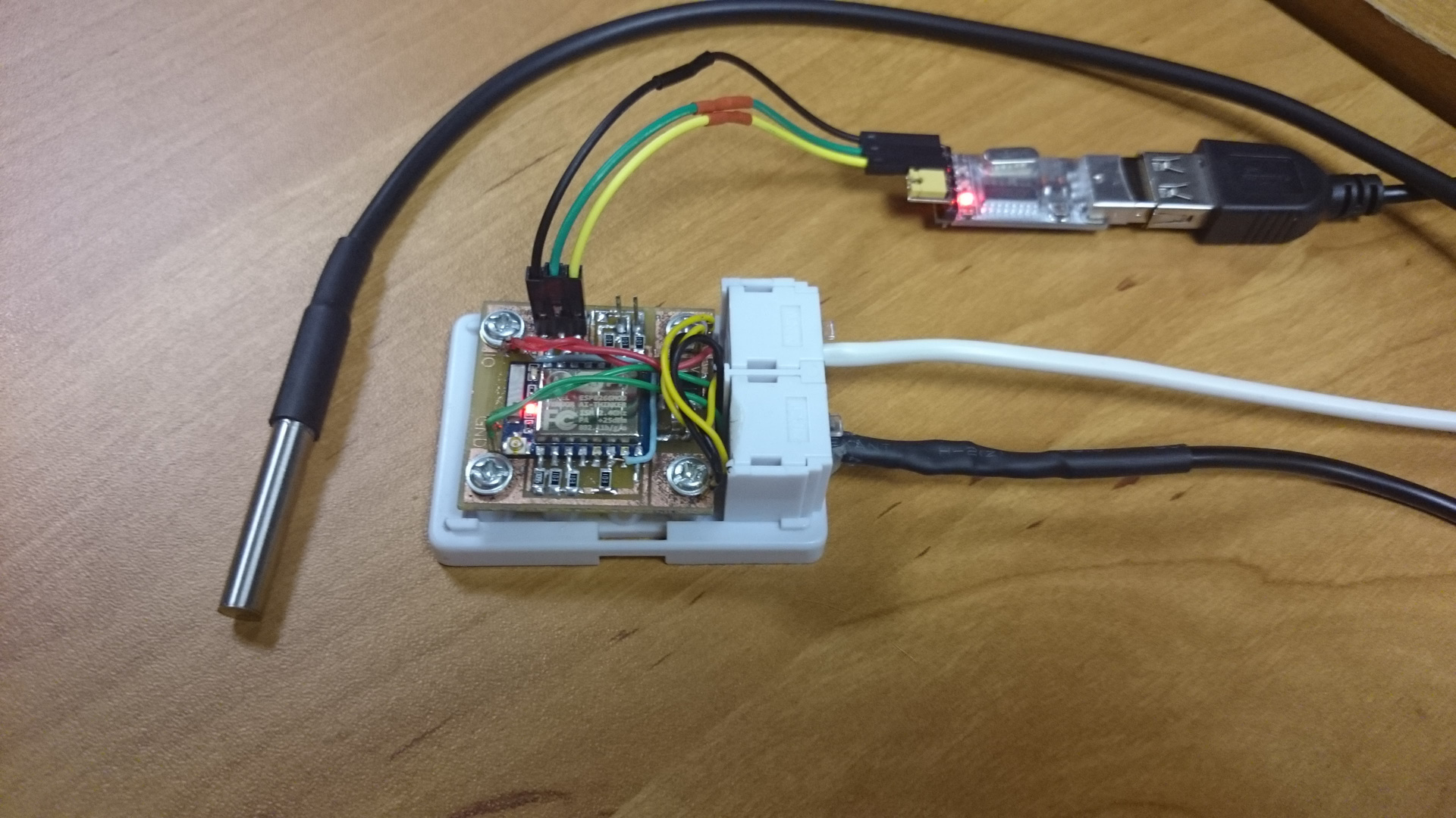
The whole system is placed in a standard telephone jack.

Four-wire telephone wiring.
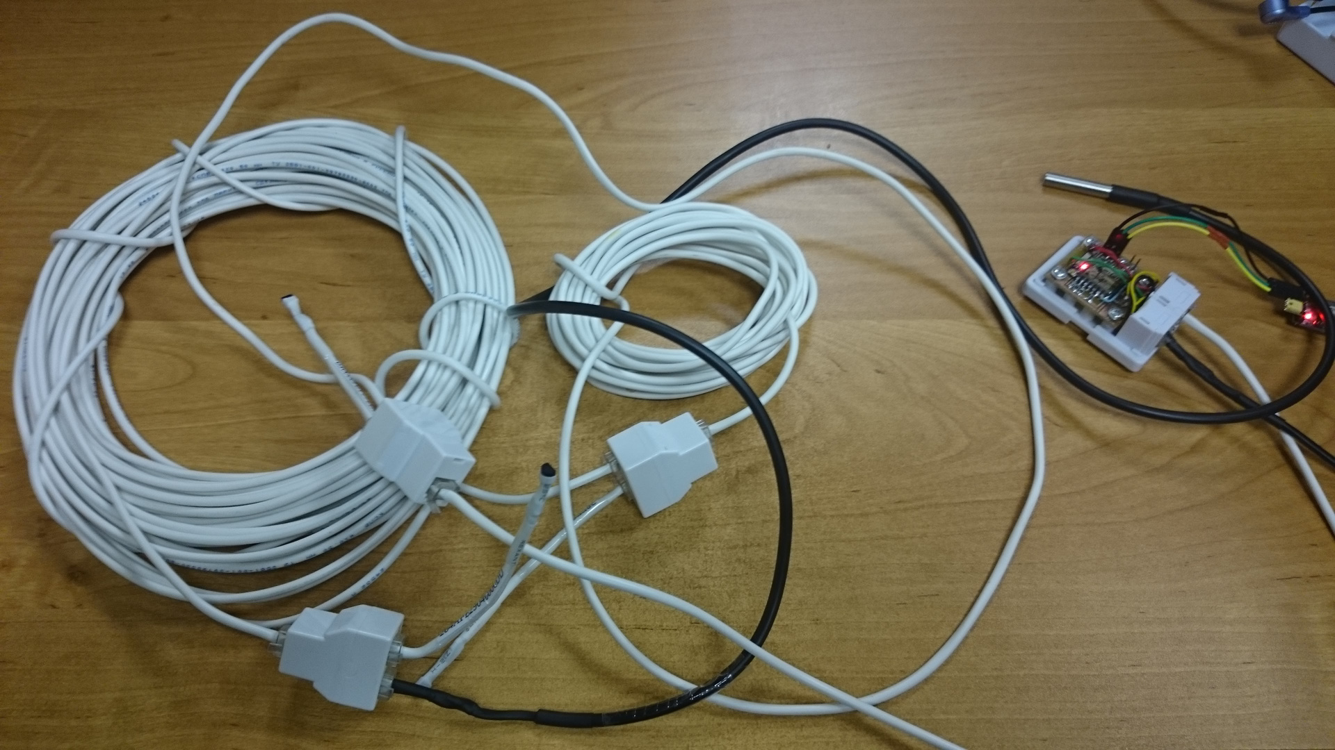
Power passive. For the pool ordered a waterproof version of the sensor.
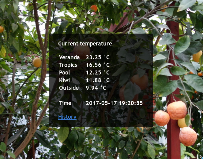
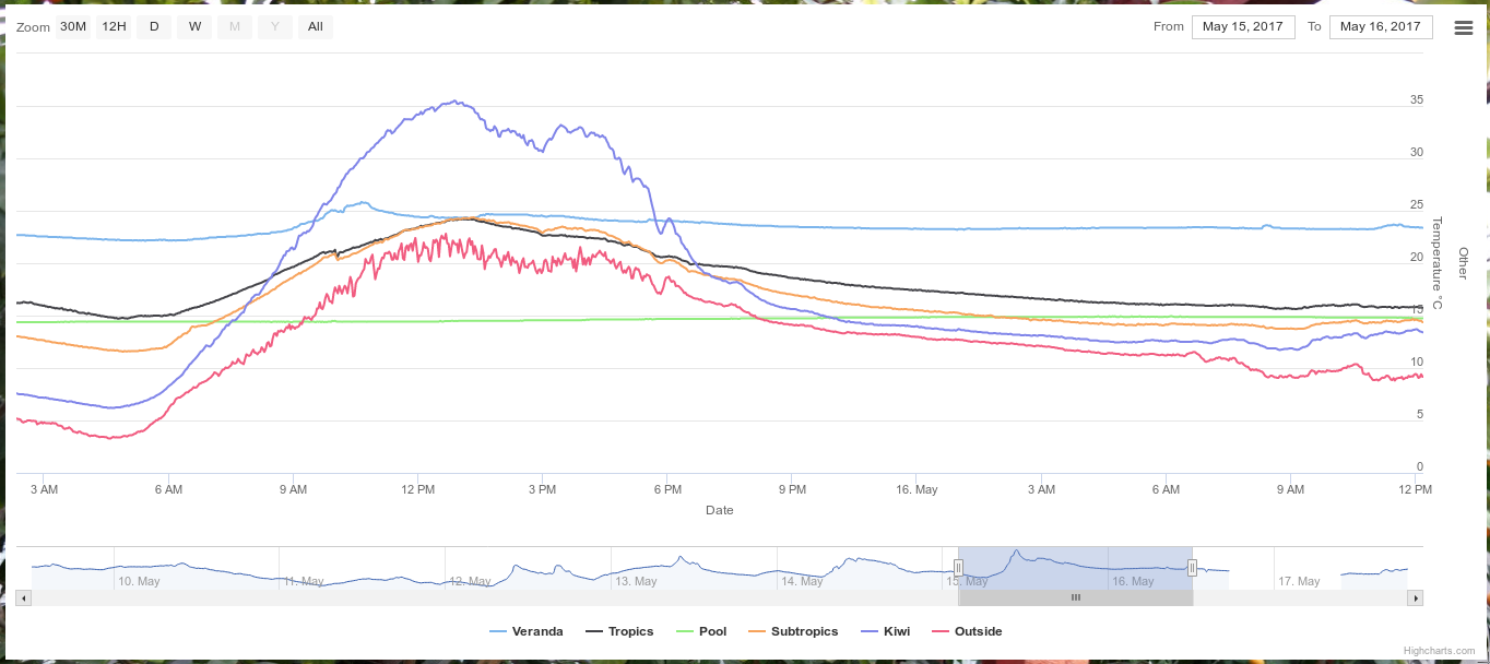
Now dad is watching the temperature on the computer.
Like this:
Well, with graphs:
Module circuit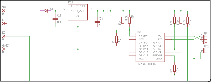
During the development process, I really liked this module and I began to think how to use it in my system, and then the problems described at the beginning of the article just came over. After a couple more experiments with these chips, I began to develop the board, which now successfully replaced the old system in the three zones of my modest home.
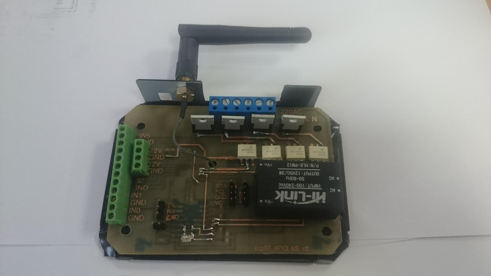
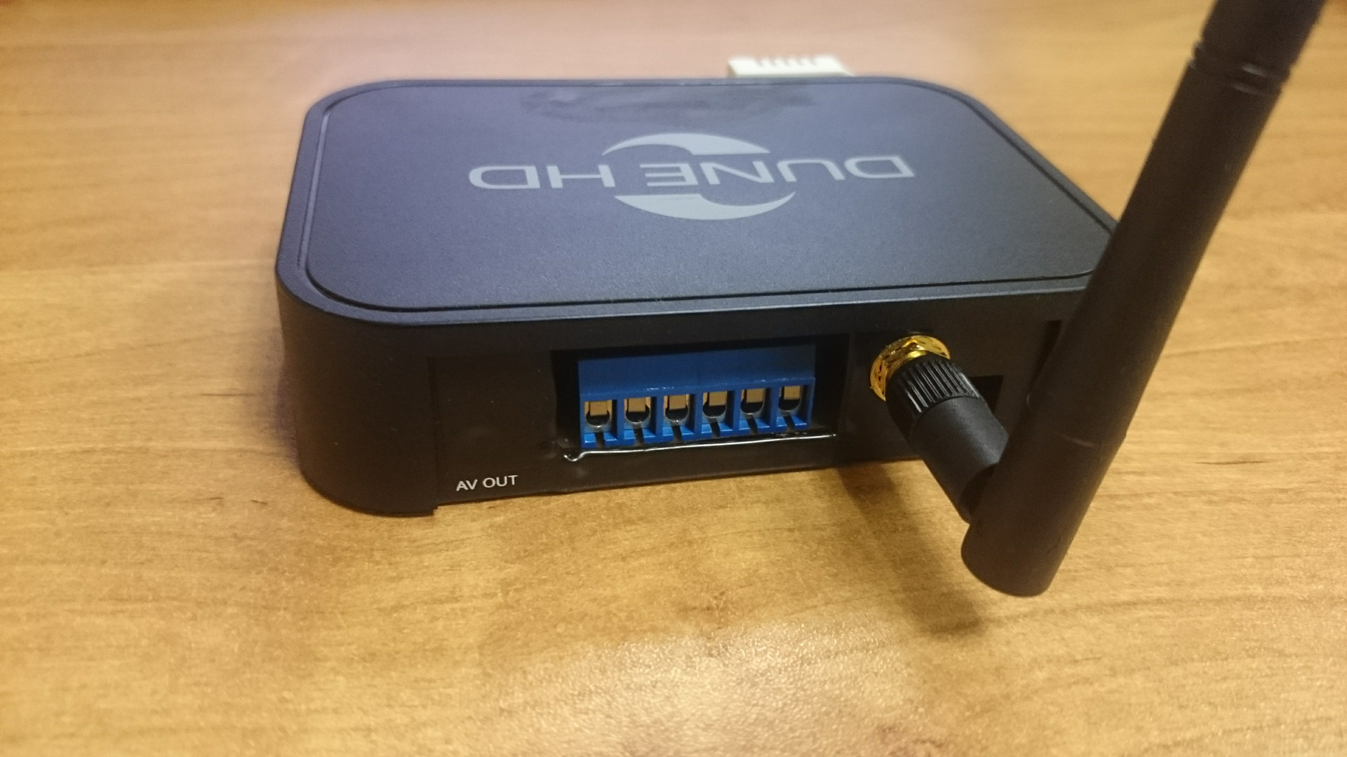
So, your attention is “esp07_4PIO_6S v2”.
Top
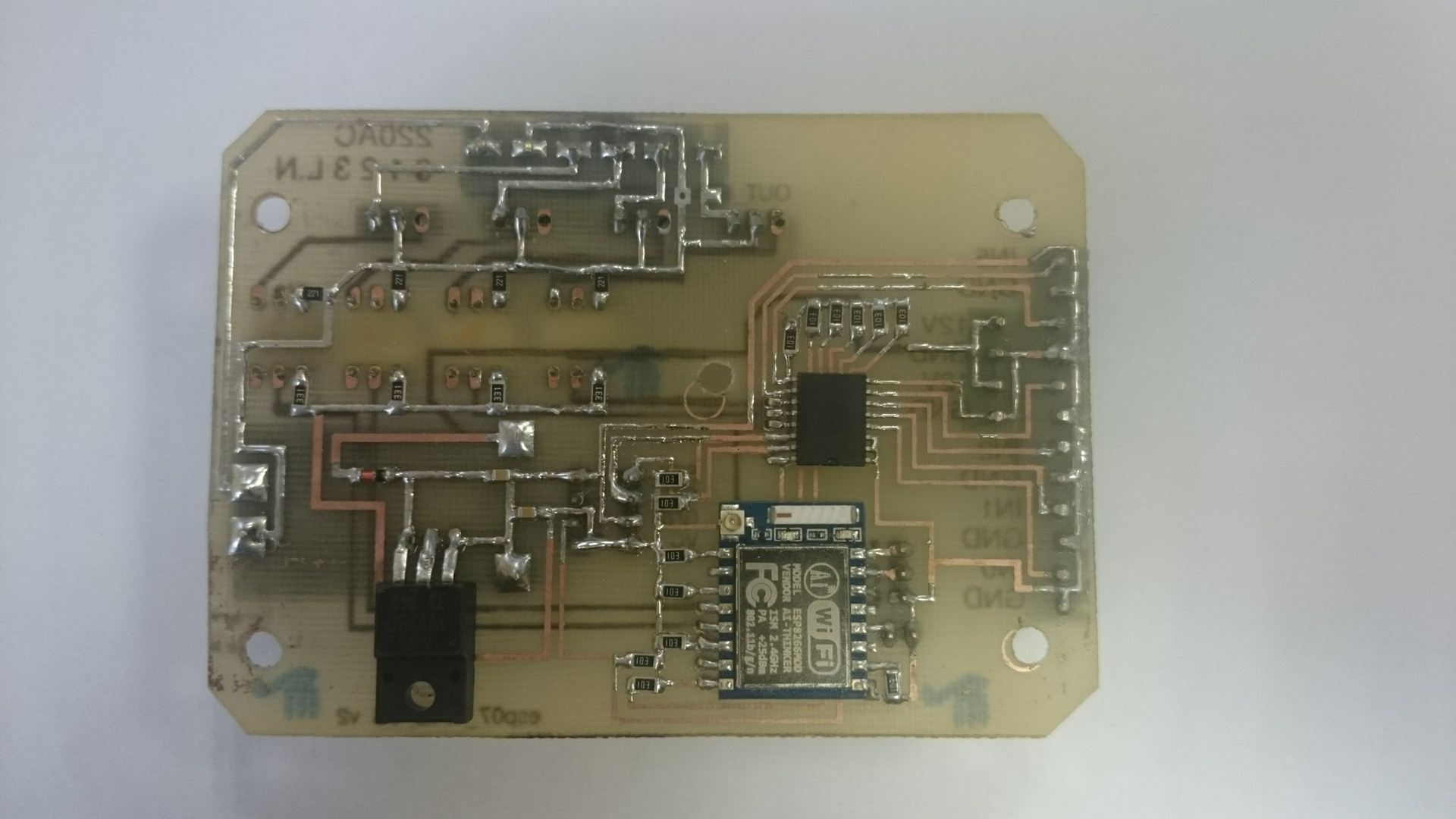
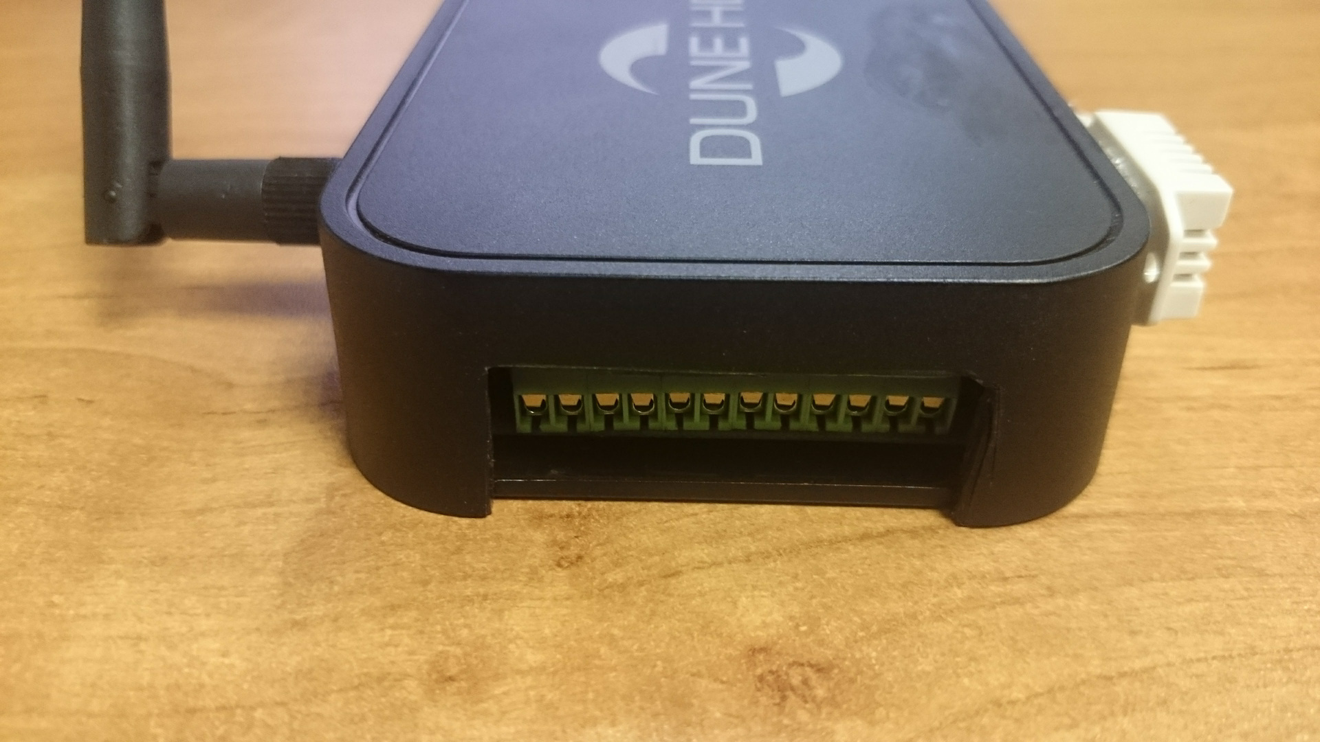
View: Bottom View:
The last time a big problem was the selection of the corps, so this time I danced from the corps. Since there were cases from the old models of the Dune media player, the choice fell on them. After completion with a file (the holes for the inputs and outputs of the media player are slightly different, it was not possible to connect 220v to the HDMI connector :)) perfectly. Only the temperature sensor had to be done outside, as the inside heats up the air.
Inputs and Outputs to 220v
Inputs and Outputs to 5v and 12v
What can this module and why is it better than the old system?
- No additional wiring is required for installation. It is powered from the same network that it controls.
- When the central server or Wi-Fi is disconnected or unavailable, it switches to offline mode and manages offline control (the script for each zone can have its own)
- Removes data on temperature / humidity / light in the room.
- It controls 4 devices 220, reads data from 6 sensors of the “dry contact” type.
- Able to independently send data to thingspeak.com and similar systems.
- Reacts faster than the old system (not that this was a problem, but earlier each sensor was interrogated twice a second, which could give a total lag of more than a second). This system works by interruption.
- Able to update the firmware "through the air."
Scheme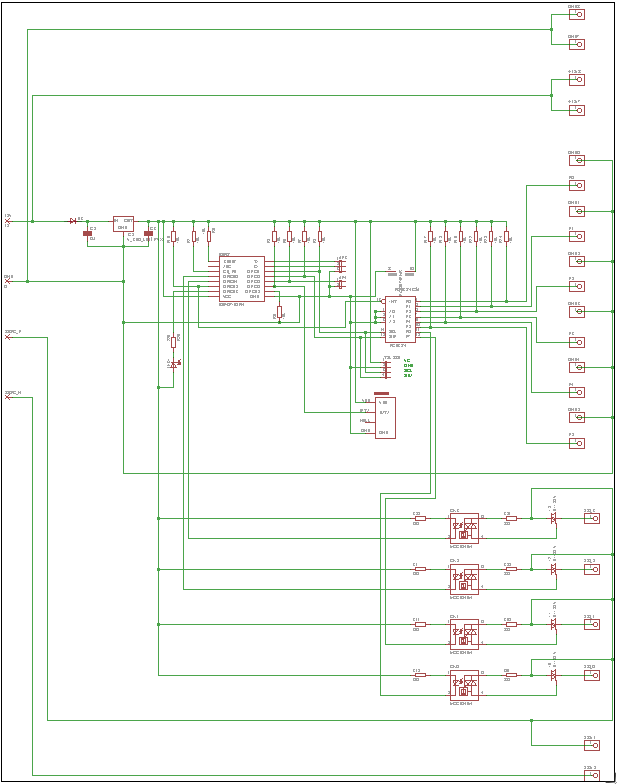
It was not possible to dissolve such a fee in one layer, so I had to master a two-sided LUT:
Pay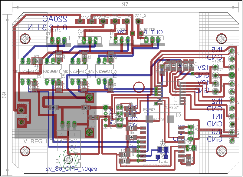
The operating experience is already more than six months, plans to replace all the control parts of the system with this module, leave only monitoring to 1-Wire.
Considering wishes for past articles, diagrams and code are available on github . Old too there have suddenly someone come in handy.
Something like this. Put likes and subscribe to new videos :) Joke, anyway new article if there is, then after a couple of years, the Chukchi is not a writer: P
Although, if you have questions about the firmware and architecture esp07_4PIO_6S, I will write a detailed article about this craft, there is, on my opinion are some interesting solutions.