Creating a drum circular grinding machine
Introduction, Background
I would like to talk about the process of designing and manufacturing a woodworking machine. Describe the process itself, in a complex, with all the nuances, with small inserts for specialization in each of the affected branches of knowledge (design, engineering, electrical engineering, manufacturing, etc.). Without deepening into excessive emotionality and process, and, at the same time, without dry scientific facts and theorizing. I focus on the popular and scientific presentation, but not without details and subjective opinion)
The background is as follows: at one time I was engaged in woodworking and I needed to grind and smoothly draw curved surfaces on workpieces made of hard wood. I started this way with a file and a hacksaw, but I quickly realized that manual labor is good only at school, and for the production it is necessary to use the energy of electricity.
I worked with a relative in the garage for the first such machine, I made the second one myself, now I present to you the third realization of this product.
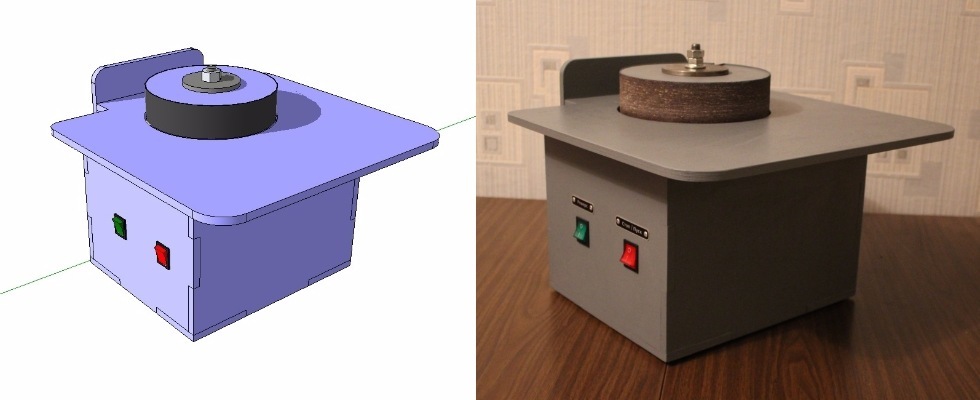
Purpose of the machine, features of operation
Such machines are designed for basic and auxiliary operations for grinding surfaces of wood products, plastics and non-ferrous metals in production and in everyday life. And in simple terms - the drum (with sanding cloth fixed on it) is spinning, and by bringing and turning the workpiece to it, you can get exactly what is required. The presence of the table (opara for hands and blanks) allows you to shoot at least 0.05-0.1 mm per pass. Or, if you need a big set-up - press harder - remove up to 0.6 - 1 mm per pass (for example, wood like oak, maple). The feed rate is just as important.
Operating - it's easier to try it yourself, rather than describe it in words. In comparison with other woodworking equipment, this type of machine is fairly safe (mill, circular saw): all movements are easily controlled, there is support for the workpiece, I eat relatively small, there are no sharp rotating parts.
Requirements and limitations
We set the following requirements for the final product:
- The machine should be as mobile and small as possible. The transfer of equipment from place to place, travel - all these factors make minimizing weight and size at the forefront.
- Dust removal should be present in the product "out of the box." When grinding, fine dust is formed, which is not at all beneficial to health. To implement this item, the design provides for the forced extraction of dust through the gap between the disk and the worktable. Behind there is a hole for connecting a standard hose from a vacuum cleaner.
- Engine power should be sufficient for grinding small and medium-sized products. Unreasonable increase in engine power will lead to an increase in mass-dimensional characteristics of the machine. We take the single-phase engine with a power of 250 watts.
- Landing the tool on the motor shaft VS decoupling of the drive and tool. Our product still more refers to the household (rather than to the prof. Tool), the engine power is small - so we can safely choose the scheme with the fit of the tool on the motor shaft. Although the separation of the drive and tool can immediately give a bonus in the form of rotational speed adjustment (through the pulleys) and reduce vibrations. But this will lead to higher prices and complexity of design, manufacture and assembly.
- Ergonomics of use. The table should not be too big and, at the same time, not too small. The height of the working surface is important (if you grind more than 20-30 minutes a day). Characteristics are selected individually.
- Lighting of the working area should be present, the light should fall from above. The ceiling must be able to move and be fixed within wide limits.
- The drum must be replaceable, with easy possibility of changing the sanding belt.
- Reverse. The drum should spin both clockwise and against (required for easy grinding of parts).
A little about computer modeling and development stages
Creating drawings of parts to transfer them to work - this is the last stage of work. Initially, I ponder the product for a long time, “twist” it in my head, compose elements, etc. Then there is a paper stage - outline features, sketches, sketches. I estimate the possibility of realizing everything drawn, I redo it - and so on in a circle. Then comes the stage of working drawings with real sizes (still on paper). Again, it is necessary to coordinate and take into account all the dimensions and details among themselves. This is the most difficult stage. Since there is no computer model, everything is in my head - there are still errors.
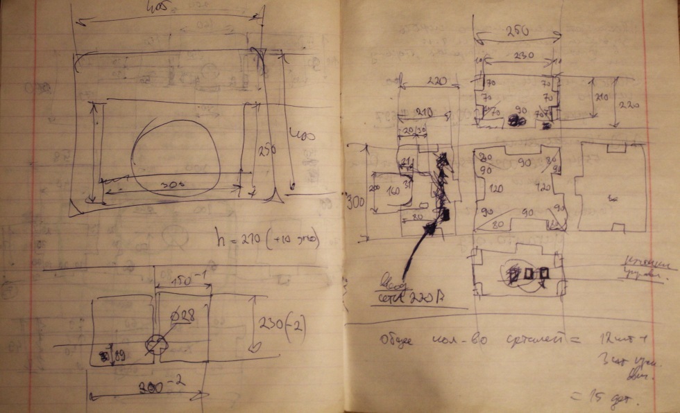
Then everything is simpler: in the 2D CAD program I am drawing the parts for laser cutting, milling, turning, etc. I use DraftSight - this program is free for non-commercial use and has almost full functionality of AutoCAD for 2D drawing + saves files in * .dxf, * .dwg formats.

Drawing at this stage is the simplest work without a hint of creativity, you just need to be careful and accurate to the size entered. Some drawings of individual parts, I generally draw on paper - and easier and faster. ESKD is not complying (and I know only partially), but turners, as a rule, understand and do everything that is required :)

I am aware of excessive simplicity and negligence in preparing documentation. Going to make changes to this process.
At least I plan to do an assembly model of the product in the 3D modeling program. Preliminary visualization of the product is much easier, faster and cheaper than creating a prototype and making adjustments after the fact.
I tried many programs (freeware) and settled on SketchUp. It is possible to quickly make a prototype (with exact dimensions): see the result, turn the product in 3D, check for errors, etc. Yes, this is not solid modeling, but only a framework of planes, but at this stage it is enough for me. The closest analogue (from free ones) is FreeCAD, but this program is still in beta testing.

In general, the most promising approach is to create a solid-state 3D model, and then, using it, we get any drawings, cuts, sections, test loads, etc. But everything has its time, it is necessary to grow to this (to have time and energy for mastering, to do a large project on this principle).
For example, in this machine I was mistaken in two places (non-critical) when ordering plywood milling. Both errors were quickly eliminated, but I realized that I had to master the preliminary assembly of parts in 3D (to avoid such phenomena in the future and simplify my work).
Manufacturing process
The engine and the drum I already had (left from the previous version of this machine). I quickly ordered the plywood (by e-mail, the parts were delivered via the postal service - I took the box from the nearest branch).
The electrical part - something was in stock, something bought in the market. The tools were all available. I drew a circuit, cut the wires, pressed it, put everything together, checked it - it works, it turns, it switches. Connections of wires and buttons are all detachable, twisted soldered and compressed. At first, I soldered the wires to the buttons, but then I switched to automotive connectors — it's easier to assemble and operate.
The drum requires balancing. If it is not balanced, the machine will literally “jump” on the table when turned on. I have a separate device for this operation.
The downside of this design is that the engine is "tightly" fixed in the machine body. But, the bearings are lubricated, the engine is reliable, there are cooling holes in the body - let's hope for the long-term operation of the product.
Now I, of course, would buy industrial asynchronous engines: they have a “flange” and “legs” by default, and the rotors in them are better balanced than in engines from washing machines.
As an additional option, I wanted to put a cooling fan in the case (from a computer, at 5-12 volts). But then he refused this undertaking - it would be necessary to insert a power supply unit, cut the hole for the fan in the case, make the power button for it, etc.
I also did not insert a thermal relay to protect the motor type RT-10.
Also (theoretically) the illumination of the workplace could also be powered from a single power supply unit located in the machine body. This would complicate the electrical circuit and installation (along with the relay and fan), but dramatically increased the level of the product, and the professional development. As a refreshment lamp, one could choose a household or industrial (36 volts lamp) an instance. LED illumination suggests itself, but an ordinary incandescent lamp (across the spectrum) is closer to me. The choice of lighting system is a separate topic for discussion.
To connect the vacuum cleaner there is a special hole with a diameter of 40 mm in the back of the case. Those. it will be possible to connect a D40 mm pipe there directly or a hose from a household D32 mm vacuum cleaner through an adapter. Those. even at the design stage, standards were used to select the diameter of the hole for connecting the dust extraction system.
Assembly - mechanics
From the cut plywood blanks glue the body.
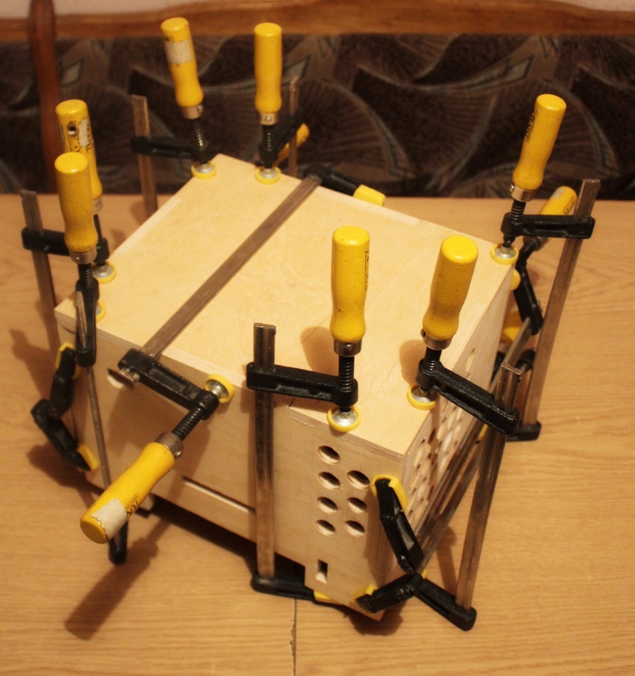
Mount the dust collector box. The vacuum cleaner will suck air through the gap between the drum and the worktable. Theoretically, dust generated during polishing will be removed together with air.

Electrician mounted in the housing.

We balance the grinding drum on a special device.
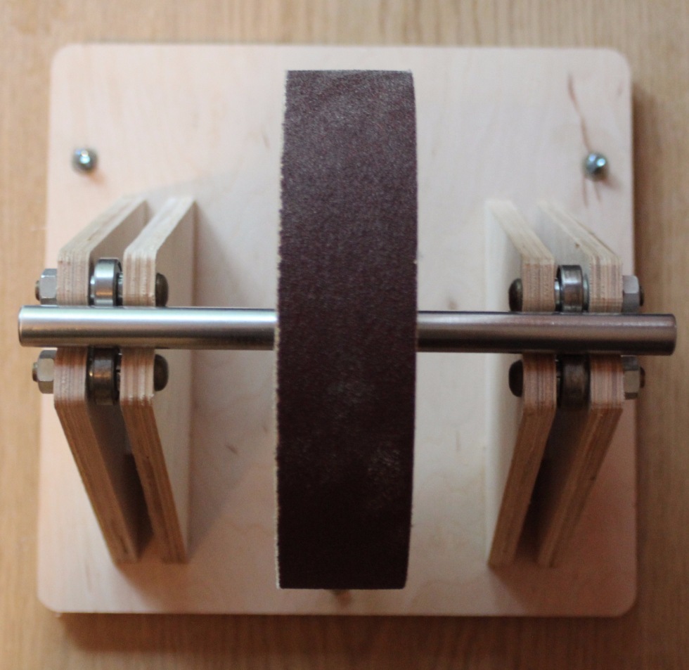
Bearings are used to ensure the rotation of the balancing shaft.

Balancing is done by drilling holes in the disk body.

All parts are ready for painting.
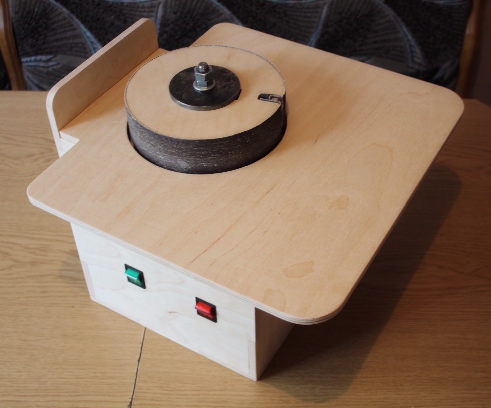
The resulting result.
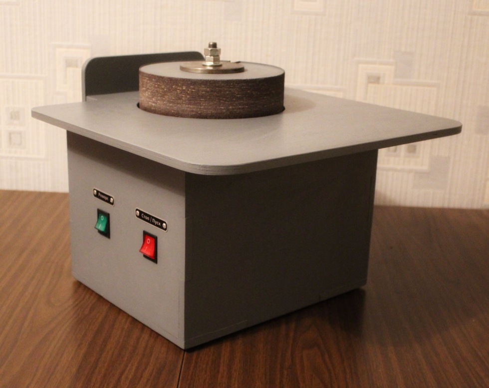
I had nameplates with acc. inscriptions. Applied them on this machine (set with rivets). It turned out quite nice and informative.

On the back of the case you can see the socket for a standard power cable and a hole (with installed plumbing bushings) for a vacuum cleaner.

Assembly - electrics
Draw a circuit diagram.
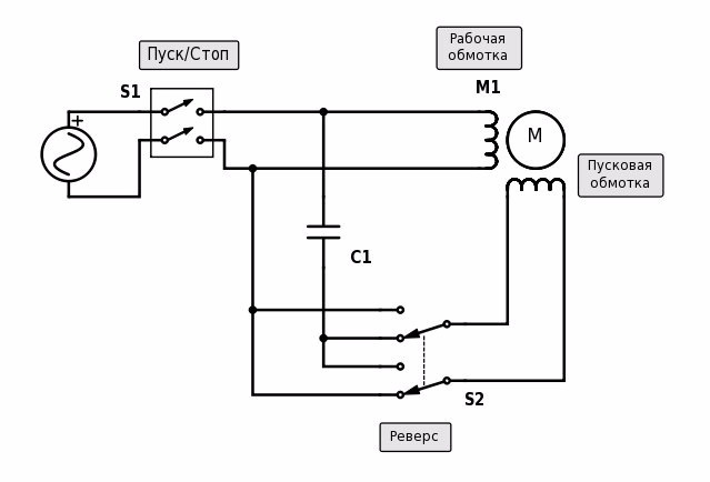
Cut the wires, crimp the ends correctly.
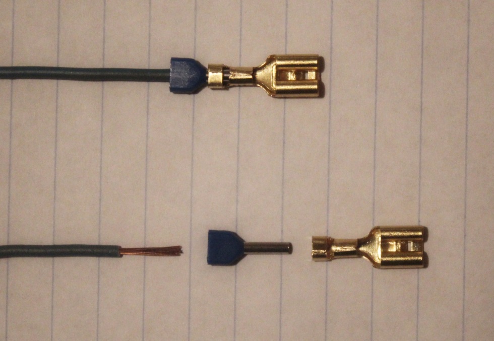
We use a specialized tool.

Putting together all the components.

Everything is mounted in the case.

Testing at work
Testing apparatus showed fairly good dust removal during grinding. The engine heats up, but a little, as it should be. The plane of the drum is perpendicular to the table (within no more than a few degrees). The machine is quite mobile and easily portable. It was not possible to stop the drum by pressing the workpiece to it (I did not press very hard). Machine vibrations at work are minimal (but still present).
The result
As a result, we have a machine with the following characteristics :
- weight: 8.5 kg
- overall dimensions (LxWxH): 400x300x350 mm
- engine power: 250 W (50 Hz, 220 V)
- grinding wheel diameter: 182 mm
- linear velocity grinding belts: 13.5 m / s
- output for connecting the dust collector: +
- removable drum (with the possibility of replacing shlif. skins): +
- rotation reversal shlif. drum: +
Disadvantages , possible improvements:
- work area lighting
- forced engine cooling
- installation of a thermal relay to protect the engine
- replaceable shlif. drums of different diameters
- tool speed adjustment
- limit the spontaneous start of the engine in a situation when the power is "gone and reappeared"
Conclusions and conclusions
Designing it is both difficult and easy. Making a truly high-quality, well-thought-out and well-developed product in small things is a long process with many iterations (repetitions).
I will be glad to hear your thoughts, comments, suggestions.
