How we prepared for the UAV Challenge 2016
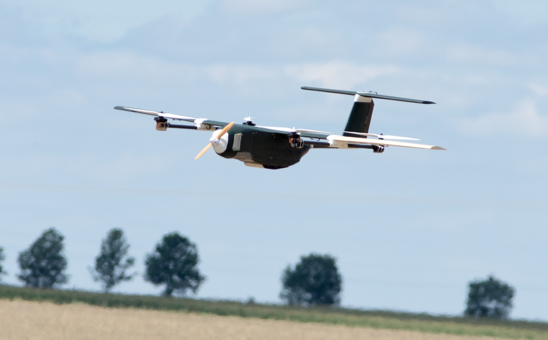
Moray's Quad-plane during test flights
UAV Challenge is an annual event aimed at empowering UAVsand, concurrently, one of the largest robot competitions in the world. The impact of events on the industry is quite large: in 2014, for example, the regular sponsors of such popular projects as the Ardupilot, PX4 and Paparazzi participated in the UAV Challenge, so many of the existing features of these flight controllers that exist today were influenced by the requirements of these competitions. Every two years, the competition is open to teams from all over the world, and at the same time the subject is a mission to save a person. This year, we also managed to get into the list of ten teams that passed the three preliminary stages of the UAV Challenge, and go to the finals, which took place from September 27 to September 29 in Dalby, Australia. The Challenge ended two months ago - since then our impressions have calmed down,
We are MelAvio Avionics Club, an association of students from the Warsaw Polytechnic University (Warsaw University of Technology). We deal with issues of programming, electronics and mechanics in the framework of their application to UAVs, and almost all of our work takes place in preparations for various competitions, the main of which has recently been the UAV Challenge. In fact, this year MelAvio took part in the Challenge for the second time: before that, two years ago, our team had already gone to the finals to Australia. Then we managed to show ourselves well with the original mechanical design and improvised flight controller, taking the tenth place in the overall standings and receiving an award for flight skills, although not fully fulfilling the mission of the competition.
Barracuda, MelAvio unmanned aircraft, at UAV Challenge Outback Rescue 2014
This year, we slightly changed the approach to participation and used a ready-made flight controller (Ardupilot on Pixhawk), modifying it to fit our needs. This is due to the fact that the Challenge conditions have become more complicated compared to the last time, and the independent development of a solution that satisfies all the conditions is a too ambitious task, it was more logical to use the existing open source projects.
Challenge Task
To make the scale of the task clear, it makes sense to briefly describe the mission submitted for the competition. The task of the teams was to deliver a blood sample from Jo - a resident of the countryside, who, according to legend, suddenly felt ill, was in his house outside the city. Joe's house is cut off from the city by floods, therefore, in order to reach it and fly back, the aircraft must, as a whole, overcome up to fifty-one kilometers of airspace along a non-linear trajectory. In addition, Joe’s position is known only to one hundred meters, and in order to give a close target and avoid harming a person, the aircraft must localize him more precisely when he is already in place. Also complicating the situation is the fact that there are almost no guarantees regarding the landscape both at the start of the mission and in Joe’s surroundings. so that the drone must have the ability to vertical or conditionally vertical takeoff and landing, as well as a system that allows with a sufficient degree of reliability to choose a suitable place for landing. The organizers of the chelendzha encourage as much as possible autonomous behavior of the drone, so the best possible approach is to completely eliminate the actions of the pilot from missions, starting from departure from the starting point and ending with landing with a blood sample at the same place. In addition to the main, "delivery", drone in the mission may be an auxiliary aircraft. A rather wide range of requirements is presented for both devices in order to ensure their safest flight and correct behavior in unforeseen situations. as well as a system that allows with a sufficient degree of reliability to choose a suitable place for landing. The organizers of the chelendzha encourage as much as possible autonomous behavior of the drone, so the best possible approach is to completely eliminate the actions of the pilot from missions, starting from departure from the starting point and ending with landing with a blood sample at the same place. In addition to the main, "delivery", drone in the mission may be an auxiliary aircraft. A rather wide range of requirements is presented for both devices in order to ensure their safest flight and correct behavior in unforeseen situations. as well as a system that allows with a sufficient degree of reliability to choose a suitable place for landing. The organizers of the chelendzha encourage as much as possible autonomous behavior of the drone, so the best possible approach is to completely eliminate the actions of the pilot from missions, starting from departure from the starting point and ending with landing with a blood sample at the same place. In addition to the main, "delivery", drone in the mission may be an auxiliary aircraft. A rather wide range of requirements is presented for both devices in order to ensure their safest flight and correct behavior in unforeseen situations. so the best possible approach is to completely eliminate the pilot's actions from missions, starting from departure from the start and ending with a touchdown with a blood sample at the same place. In addition to the main, "delivery", drone in the mission may be an auxiliary aircraft. A rather wide range of requirements is presented for both devices in order to ensure their safest flight and correct behavior in unforeseen situations. so the best possible approach is to completely eliminate the pilot's actions from missions, starting from departure from the start and ending with a touchdown with a blood sample at the same place. In addition to the main, "delivery", drone in the mission may be an auxiliary aircraft. A rather wide range of requirements is presented for both devices in order to ensure their safest flight and correct behavior in unforeseen situations.
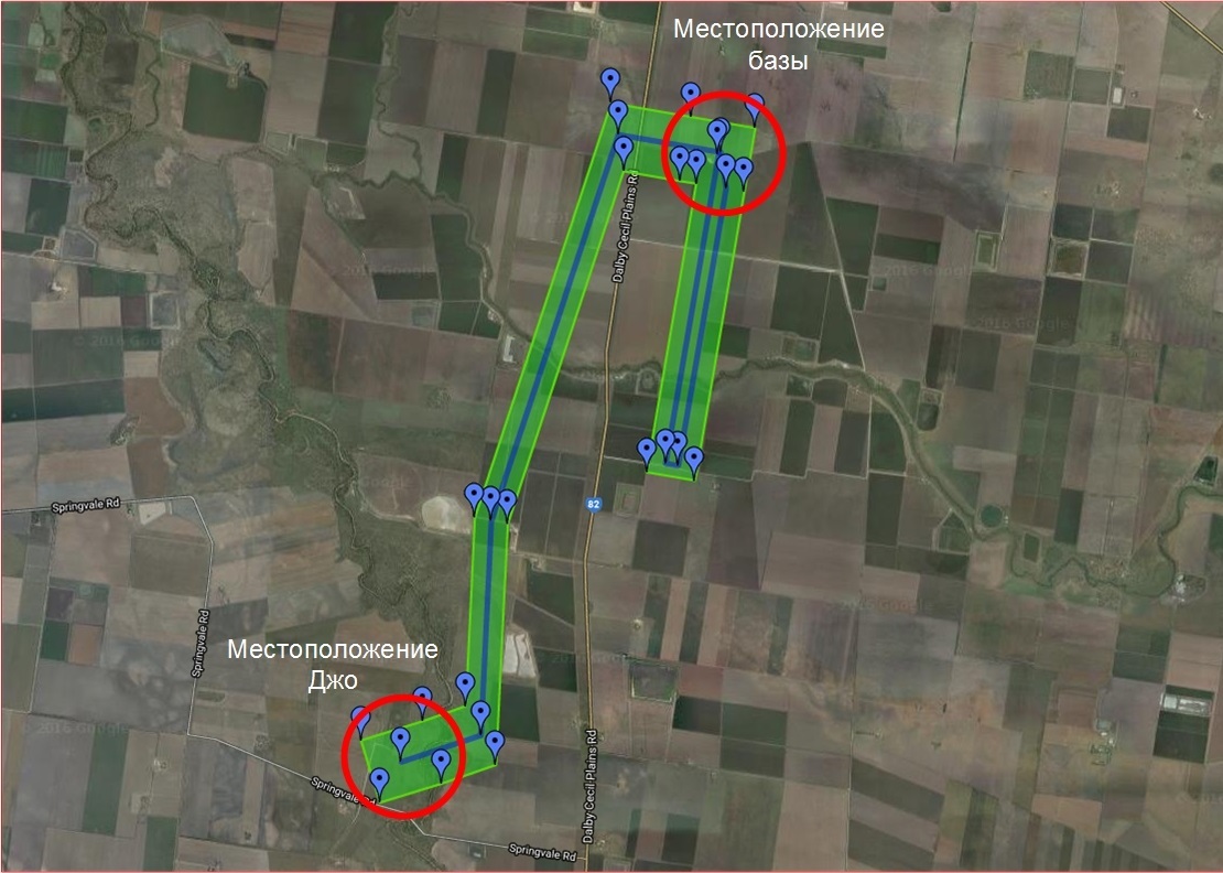
Map with designated departure, destination and allowed area of flight
Main aircraft
As the main drone for the mission, we decided to use a quad-plane - a combination of a quadrocopter and a classic aircraft. The need to ensure vertical take-off and landing immediately removed from our attention the standard fixed-wing schemes, so that the tiltrotor and helicopter were the main alternatives to the chosen option. The version with tiltrotor was rejected due to the fact that with a fixed screw pitch, the tiltrotor engines are doomed to low efficiency, which was unacceptable for us due to the estimated required flight range; the construction of a convertiplane with a variable screw pitch assumed the degree of mechanical complexity with which we, as a student scientific organization, could not deal because of limited resources.
Design
Before designing a “serious” quad-plane model, we assembled a test model — an apparatus that we called “Ugly.” This hybrid was made on the basis of the finished purchased model aircraft and was designed to test the performance of the very idea of a quad-plane, as well as all the innovations that we adapt in the flight controller. After we were convinced that we could actually fly on this configuration of a drone, we began to develop a larger model.
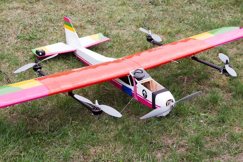
Test aircraft
From the very beginning of development, it was clear that copter screws and engines would create additional resistance and imbalance in the aircraft mode, so we decided to try to make the design of the aircraft itself as “slowing down” and as stable as possible. In addition, our initial requirement was to keep the maximum space in the aircraft body, so that the equipment of the computer vision system and lithium-polymer batteries with a capacity sufficient to fulfill the entire mission fit in (the aircraft is fully electric). Based on these considerations, we chose a high-wing aircraft with a trapezoidal wing of medium elongation and a T-shaped tail; the angle of the transverse wing V was chosen to be one and a half degrees.
With the indicated initial data on the design and the assumption of the mass of the aircraft, we began to develop. First, with the help of the Profili 2.0 application, a suitable version of the profile of the main wing of the aircraft was chosen, after which in XFLR5 we clarified the shape of the wing and tail in the volume. In addition, in ANSYS Fluent, we checked that engine engines and propellers located in the immediate vicinity of the wing do not make a critical change in the character of the air flow on the wing. Upon completion of these procedures, we proceeded to a more detailed study of the entire structure in SOLIDWORKS.
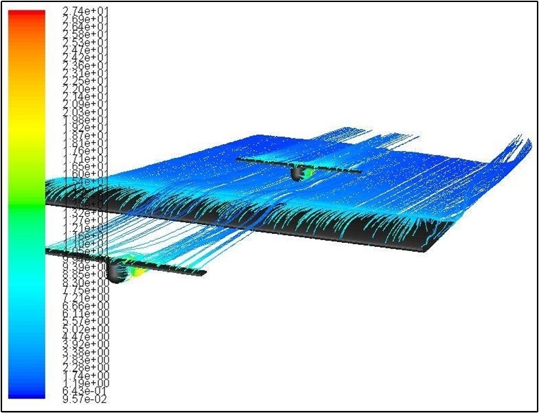
Check flow on copter screws in ANSYS Fluent
When working on the design, special attention had to be paid to the body of the aircraft and the wing, since they have the maximum number of parts and have the greatest influence on the carrying capacity and dynamics of the aircraft. A special approach to these elements was necessary not only during development, but also during assembly, since it was necessary to make them as light as possible while maintaining their sufficient strength.
The wing of the aircraft was made of three components: the center section and the right and left consoles. The basis for the wing design was extruded polystyrene foam. Parts of the wing were designed in such a way that their surface was straight, and thanks to this, a CNC wire saw could be used to precisely cut polystyrene. After that, polystyrene blanks were subjected to additional processing in order to increase their strength and improve aerodynamic characteristics. Thus, the center-section blank was laminated with carbon fiber and polyester resin; In order for the workpiece to retain a smooth and even surface, it was wrapped with Plexiglas for the time of lamination, placed in a vacuum bag and secured in foam polystyrene negative. For the manufacture of wing consoles it was not possible to use carbon fiber, including for the reason that it was necessary to place radio transmission equipment in these parts (coal creates interference), therefore the consoles were laminated with a layer of fiberglass and balsa. At the edges of the elements were made attachments for their assembly into the one-piece structure of the wing. Also in the wing was cut out a place for a radio transceiver, drives for ailerons, wires and other equipment; In the necessary places, the fasteners for the equipment printed on the 3D printer were glued in the cutouts. At the edges of the elements were made attachments for their assembly into the one-piece structure of the wing. Also in the wing was cut out a place for a radio transceiver, drives for ailerons, wires and other equipment; In the necessary places, the fasteners for the equipment printed on the 3D printer were glued in the cutouts. At the edges of the elements were made attachments for their assembly into the one-piece structure of the wing. Also in the wing was cut out a place for a radio transceiver, drives for ailerons, wires and other equipment; In the necessary places, the fasteners for the equipment printed on the 3D printer were glued in the cutouts.
In places where the wing consoles are connected to the center section, fastenings were also provided for the longitudinal beams, at the ends of which there are engine engines. Mounts wing consoles, kopternyh beams and tails were printed with nylon technology SLS with high accuracy. Copter motor mounts were laser cut from plywood and glued with polyester resin.
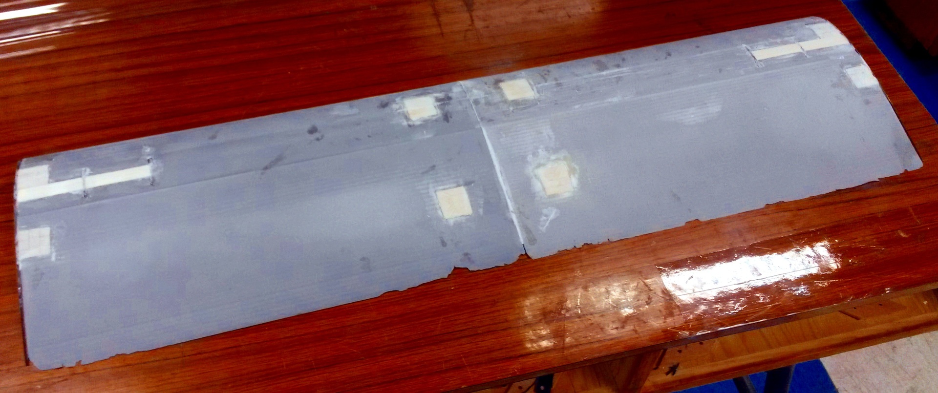
Center plane in the manufacturing process
The frame of the case was also made of plywood. The necessary details were cut out of plywood with a laser, and then glued together into a single structure using cyanoacrylate glue. The frame was covered with balsa, reinforced on the nose and on the bends with carbon fiber, and then laminated with fiberglass. The design provided space for a camera with a stabilizer (front of the hull), batteries (rear of the hull), as well as an onboard computer and flight controller (middle of the hull). In addition, connections for the wing and tail boom were worked out, which made it possible to conveniently arrange the power and signal wires inside the aircraft structure.
The stabilizer and elevator were made according to a method similar to the manufacture of an airplane wing.
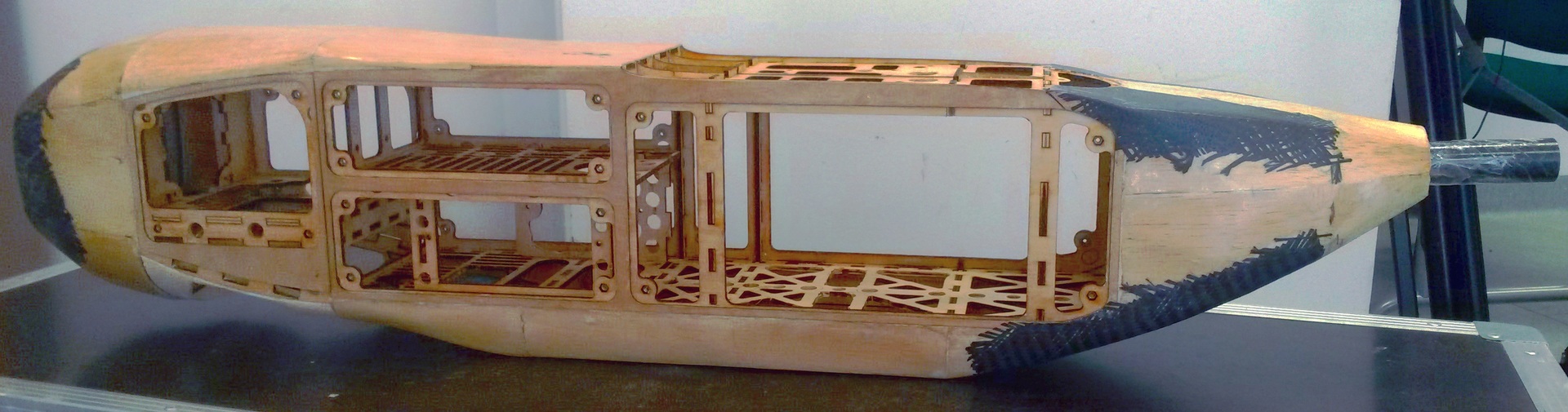
Drone hull frame
Power unit
As the copter motors for the device, we took the largest ones that were for us in the operational access zone - the T-MOTOR U8 Pro 170KV with the recommended for these motors wooden propellers from T-MOTOR with a diameter of 20 inches. ESC'and T-MOTOR FLAME 80A were chosen to control the speed of the motors. Powered by two six-cell Tattu 22000mah lithium-polymer batteries connected in series, this powerplant allowed us to get the maximum vertical thrust of 20 kilograms.
For the propulsion installation, we chose the Scorpion HKIII 4035 500KV motor with ESC FOXY XR-120 OPTO powered by the same battery to which the copter motors are connected.
The total take-off weight of the aircraft with all the equipment on board was equal to 14 kilograms. The maximum speed of the vehicle is 40 m / s, cruising speed is 25 m / s, the speed of stall disruption is 18 m / s, the duration of the flight in airplane mode is more than one hour, the flight range is up to 100 km, which should ensure that we can mission even in adverse weather conditions.
Computer vision system
An important part of the main aircraft for us was the on-board computer vision system, without which Joe could not be found and the mission could not be completed. The main elements of the system were selected RGB camera JAI GO 2400 with full-frame transfer and Full HD resolution, and a powerful mini-computer GIGABYTE BXi7-5775. The camera was fixed on the stabilizing gimbal of our original mechanical structure controlled by the Alexmos controller - this allowed us to obtain images with a constant level of inclination relative to the ground, so that the silhouette of the person was clearly distinguishable. The computer was connected to the flight controller to enable telemetry data and commands to be sent. In addition, using a 4G modem, the computer was granted access to an FTP server, through which communication with the station of the computer vision system operator was carried out. The algorithm of the program launched by us on board is briefly described in the next paragraph.
After receiving the image from the camera, the last telemetry data packet received from the flight controller is immediately attached to it, so that for each pixel in the image it is possible to approximately calculate its geo-coordinates. After this, a search for areas of interest is performed: an image histogram is built for this, and levels are selected in it, the number of pixels for which more than a certain threshold value is the level of “uninteresting” regions, and the corresponding pixels are no longer considered. On the remaining “interesting” pixels, morphological erosion is performed, so that only the pixels are combined into groups - these groups are sorted by concentration, size and color, and as a result we get a ranked group of areas in the image that can be at least similar per person.HOG is a descriptor and, using the vector of support vectors, we classify it as human or non-human. If a region is classified as a person, this does not mean that we immediately consider it as such - it simply receives a significant plus in the rating. After that, images of all found areas of interest are sent to the FTP server in the order corresponding to their rating. The file of each such image includes information on the geolocation of the region and the identifier of the complete image from which the region is taken.
The application at the operator’s station allows you to view images of areas of interest uploaded by the device to an FTP server, together with a map of the area over which the device is flying, and sort them by rating and time. If any area of interest causes suspicion to the operator, then he, again through an FTP server, can send a request to the aircraft, so that he will upload a full photo to the server corresponding to the selected area of interest. In addition, if in one of the areas of interest shown, the operator recognized the person being sought, he can send the preferred touchdown coordinates to the onboard computer and the computer will forward them to the flight controller.
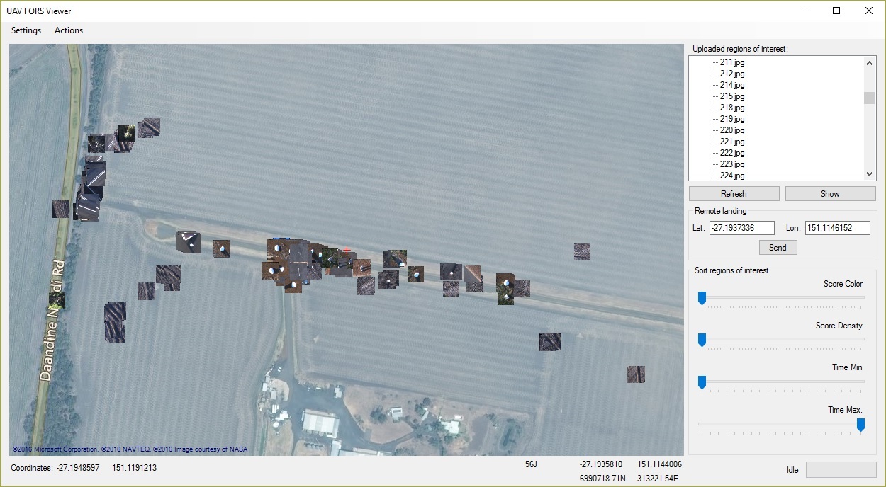
Application at the operator’s station
The reference vector machine for classifying a person was trained on examples of photographs taken during test flights. Before calculating the HOG descriptor of each of the areas of interest, we perform some geometric transformations on the area so as to bring the potential person in the image to a vertical position, since the traditional HOG works well for classifying a person only in a standing position.
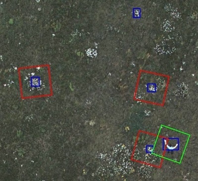
Classification of regions of interest on board the drone: red outline - the region is classified as non-human; green contour - the region is classified as a person.
Since the task was not only to find a person, but also to choose a suitable place for landing, in addition to the operations described above, the computer vision system on the main aircraft was programmed to perform the classification of the territory over which the device flies. Among the possible classes were identified: land, asphalt, grass, bushes and trees, unspecified obstacles; classification is based on information about the color and heterogeneity of the image in this place. When the workstation operator needs to make a decision about the landing site, he can request information from the aircraft on the classification of the map section of interest.
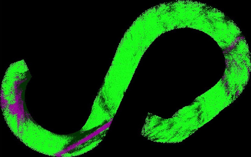
The classification of the regions of the earth's surface along the path of the aircraft: light green - grass, dark green - trees and bushes, purple - asphalt
Auxiliary aircraft
In addition to the described main drone, we decided to use an auxiliary, which would be responsible for relaying in the communication channel between the ground station of the operator and the main aircraft. Indeed, if our main drone is several kilometers away from the ground station, maintaining direct radio communications to receive telemetry data and transmit commands becomes problematic, both because of a decrease in signal power with increasing distance and due to the appearance of obstacles on the line of sight antennas on the ground and on board the apparatus. It is not always possible to cope with the difficulty of establishing direct radio communications by increasing the signal power, because, first, there are government restrictions that determine the maximum allowed signal strength, and, second, an increase in power may not bring a positive result, especially when the aircraft is at a low altitude at a great distance. We solve this problem by adding a repeater, which is located at a high altitude, in the line of sight both from the operator’s station and from the “working” aircraft.
Power unit
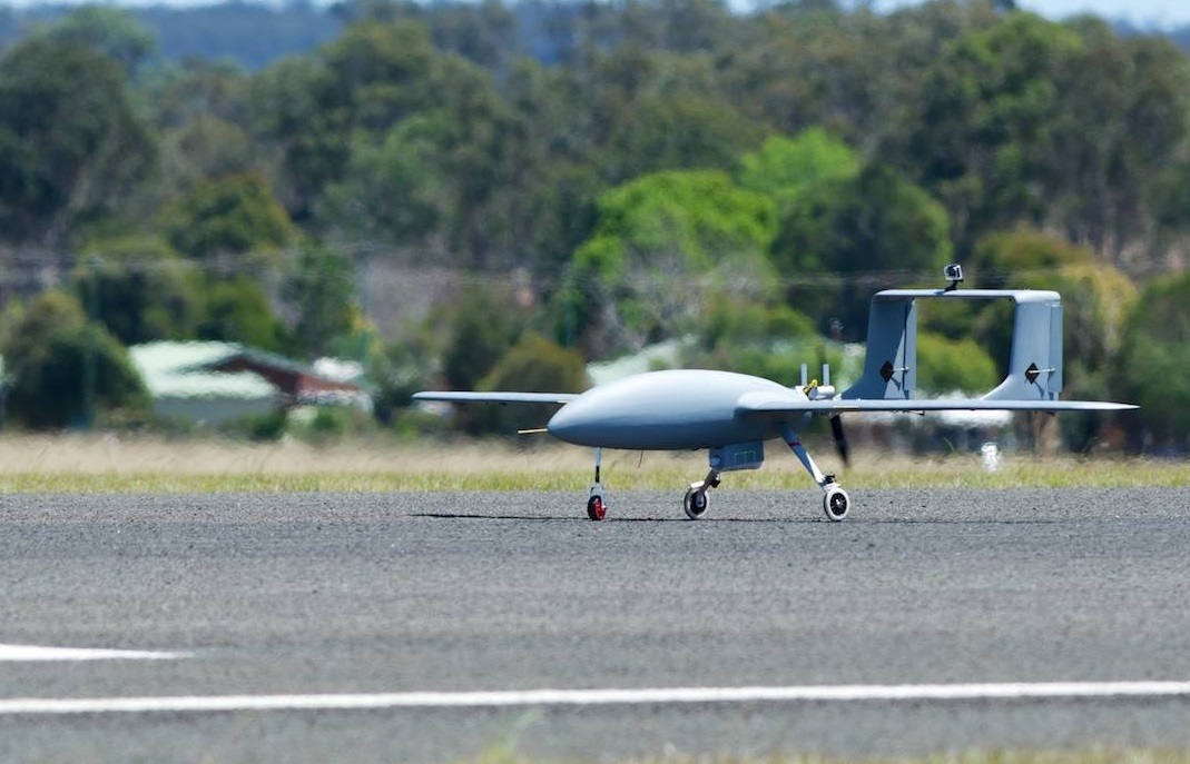
To transfer the relay equipment, we used a flying wing, made on the basis of the rather popular Skywalker X8 platform. The flying wing in this case fits into the limitations due to the unknown landscape of the launch pad, as it can be launched from a light catapult or from a bungee, and can land automatically without requiring significant open space for this. In order that the aircraft could land without landing gear, without receiving significant damage, we laminated the lower part of the hull with Kevlar and fiberglass. In addition, in order to increase the strength of the structure and to enable flight at higher speeds, the front edge of the wing was also laminated with fiberglass. The X8 was equipped with a 710 KV engine, nominally designed to work with a five-cell lithium polymer battery, and a battery for this engine for 16 amper-hours of six cells. Due to the fact that we used a battery with a voltage higher than the nominal voltage of the engine, it was necessary to provide additional air in the design for cooling. For the engine used speed regulator at 70 A and a folding propeller 9.5x8. On the elevons, we have set the high quality Hitec HS-5625MG serv; The server has a significant margin in performance, which should minimize the possibility of losing control surfaces, each of which is crucial in the case of a flying wing. In addition, additional small batteries for avionics and the emergency termination system, as well as a flight controller (Pixhawk) were located on board. As a result, the characteristics of the device were as follows: weight - 3.5 kilograms,
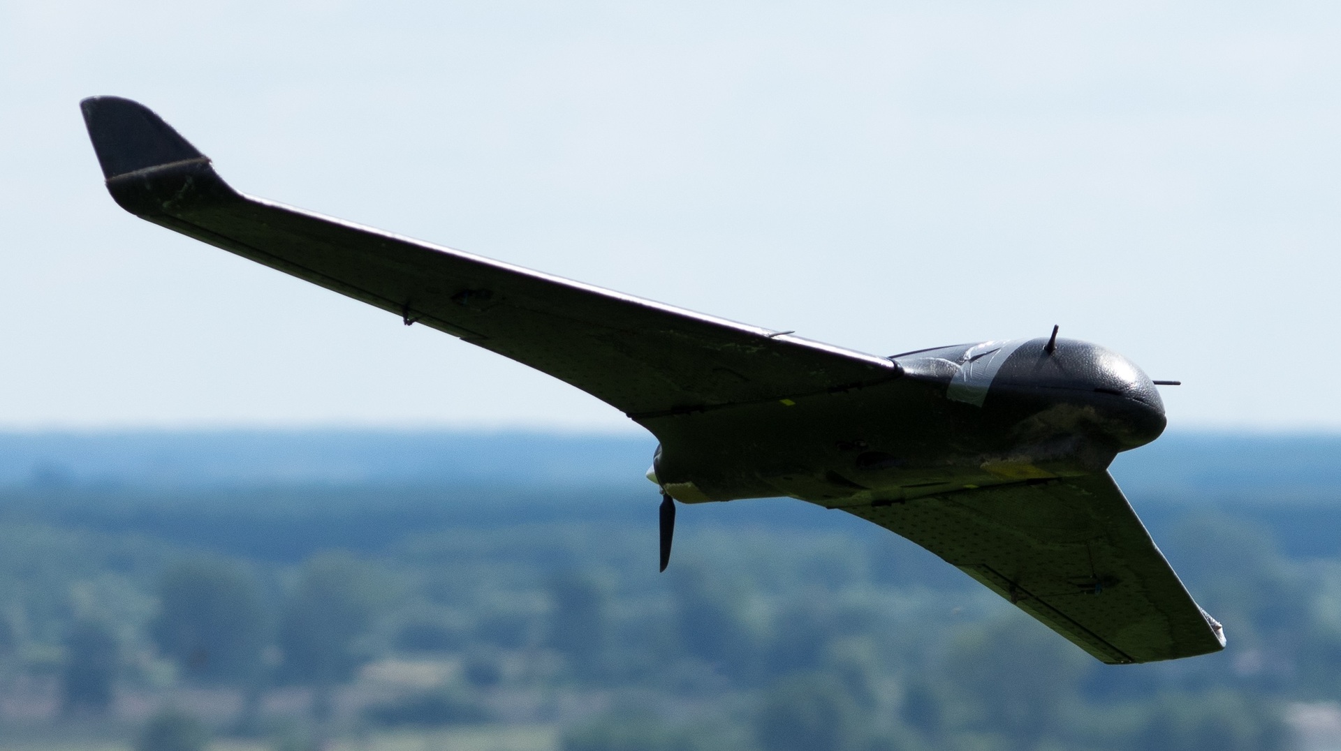
Auxiliary aircraft during tests
Organization of communication
It should be noted that adding an additional aircraft to the system to increase the coverage of the connection leads to the problem of organizing the connection itself, since in this case, in addition to analyzing the telemetry from the main drone and sending commands to it, the base station must support full-scale communication with the auxiliary aircraft by the apparatus. Of course, this communication can be organized by adding two additional radio modems (one for an auxiliary drone and the other for a ground station) operating in a channel that does not interfere with the equipment already existing in the system. This option, however, is not optimal due to additional costs and the lack of flexibility to scale when adding new UAVs to the system. The best option is to use for communication with the auxiliary aircraft already existing radio transceiver on it. In this case, the communication scheme in the system looks as shown in the diagram below.
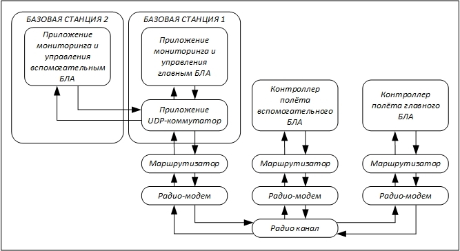
Communication scheme between the aircraft and the operator's station.
As it was written above, there are only three radio modems in the system that are responsible for resolving transmission conflicts when accessing the only radio channel they use. Two base stations used to monitor and control each of the aircraft receive and transmit through the same radio modem, access to which is regulated by the switch application installed at one of the stations (such an application in our case was mavproxy). Packet exchange between monitoring / control applications and the switch application is performed using UDP.
Of particular note is the role of the module “Router” in the above communication scheme. This module simply passes packets coming from the flight controller or base station connected to it, and takes packets from the connected radio modem to take one of the following decisions: ignore the packet, send the packet back to the radio modem, send the packet to the connected flight controller or base station . The router ignores the packet if it has already met this router before. If the packet has not been previously encountered, but is not intended for the device to which the router is connected, then such a packet is sent back to the radio modem. In other cases, the packet is sent to the device connected to the router. During our last tests,
Regarding the problem of the router determining whether the received packet is intended for this device - the solution is not entirely trivial. The fact is that for communication with aircraft, we use the mavlink protocol, which is the de facto standard for user UAVs. In the mavlink headers there is no information about the recipient of the packet, although there is a system identifier and the sender’s sub-network. In our case, only the flight controller of the auxiliary device should deal with the interpretation of commands from the “Base Station 1”, and only the flight controller of the main apparatus from the “Base Station 2”, so we could sort the packets having only the sender's ID. This solution works quite reliably, but, again, it is small-scale and needs further processing.
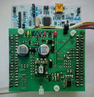
Router filtering packets coming from a radio
modem We used RFD 868+ as radio modems. The routers were made by us on the basis of STM32 Nucleo, to which we added a shield, in order to simplify the connection of power to the board, to expand the possibilities of communication and indication.
Conclusion
According to the requirements of the competition for the passage into the final part, each of the described aircraft flew more than five hours; During these test flights, we identified and fixed many minor and significant problems and errors. Our video report for this stage looked like this:
One of the most unpleasant errors of the mechanical design, which was noticed by us during the preparatory flights, was the considerable asymmetry of the load on the copter motors during the conversion from the airplane mode to the copter. The fact is that the positive angle of attack of the wing of the aircraft at low speeds deflects beams with copter motors backwards, so that two motors closer to the tail of the plane receive a large load during conversion. In addition, the jet torque from the propeller of the aircraft creates an additional load on the motors on the left side, so that the left rear engine is the most intensely working. In our case, such unevenness several times led to malfunctions of the power plant and unstable behavior of the aircraft, which once ended in a fall with severe damage to the hull. By the time when we identified the reason for such incorrect behavior of the device (three months before the competition), it was too late to make changes to the mechanics or to try to adjust the conversion program, so we took the risk of continuing to participate in the competition, knowing that our design does not have redundancy in case of an accident . Nevertheless, we tried in every way to minimize the possibility of a malfunction, as much as possible controlling the serviceability of all elements, connections and fixtures before each flight.
Unfortunately, the precautions we took were not enough, and our quad-plane crashed during one of the test flights that we performed in Australia in order to check the serviceability of the structure after the device was assembled at the competition site. In the event of a crash, the entire structure suffered significant damage, so it was not possible to repair the device and try to perform at least part of the mission. The organizers, however, treated our situation with understanding and gave us permission to perform the flight with an auxiliary device in order to check the range of our radio communication and the ability to control the device behind the line of sight.
In the end it should be said that none of the teams this year failed to fully accomplish the mission of the competition, which was associated with the loss of aircraft for various reasons: a crash, a fire, a flight beyond the allotted flying space and, as standard, a tree hang. The team from TU Delft (original mechanical design and test sample of computer vision system from Parrot, video about the UAV here ) and Canberra UAV (took a blood sample, but smashed an auxiliary helicopter, video about the UAV here ) were the most noted during the challenge .
For us, as well as for other teams, the Challenge served as an excellent platform to try our hand and communicate with professionals in the field of drones from around the world. We got a great experience and collected a lot of material that will help us in the future in our personal projects and in preparation for the next competition.
Materials
" Rules of the UAV Challenge Medical Express 2016.
" An article from the organizers of the Challenge about the statistics and history of the competition.
»A description of Canberra UAV success from Andrew Trigell - the ideological leader of the team.