DIY Racing FPV Drone (Part 1) - Assembly
- Tutorial
Today, the popularity of racing on drones is growing rapidly. Amateur poets grow into serious international competitions, and the number of people involved in this hobby is growing in progression. I myself recently assembled a FPV-quadcopter of the 180th size (the distance in mm between the axes of the motors diagonally) and I hasten to share this experience.

I described the entire build and configuration process here and here , and below will be a slightly modified version containing more information from my previous articles.
I will leave out the question of entering this hobby and go directly to the quadcopter.
A year ago, quadcopters of the 250th size were the most popular. But now pilots prefer to assemble smaller devices, which is very reasonable: the weight is less, and the power is the same. I chose the 180th size not for some practical reasons, but as a sort of challenge for the assembly.
In fact, this approach to the selection is not quite correct. It is much more reasonable to choose first the size of the propellers, and already under them - the smallest frame, where the chosen propellers fit. And with this approach, the 180th format is generally rejected. Judge for yourself: the 210th format allows you to put the same 5-inch propellers that the 250th, while the quadric itself turns out easier, and the 4-inch propellers fit into the 160th frame. It turns out that the 180th size is such an intermediate format that is “neither ours nor yours”. It can also be considered weighted 160th. But, nevertheless, I chose him. Perhaps because it is the minimum size that is capable of more or less comfortable with a GoPro or Runcam camera.
Let's start with the motors. "Intermediate" size of 180, as well as the richness of their range, complicate the choice. On the one hand, you can take what goes on the 160th, on the other - what is set on the 210th or even the 250th. It is necessary to proceed from the propellers and the battery (the number of cans). I see no reason to use the 3S battery, but for the propellers, the general rules are:
In my case, I have a 4 inch propeller size limit, but I have no motor limit. So, the three-blade 4045 bullnose propellers would be the most sensible. They are difficult to balance, but with them control is more responsive and predictable, and the sound is quieter. On the other hand, with two-bladed propellers, the speed of a quadrocopter is higher, but I don’t really need it. “Among the people” in the 180s frames the following setups predominate:
In fact, the frame allows you to put the motors from 1306-4000KV to 22XX-2700KV. By the way, I don’t know why, but the 1806-2300KV motors are now in disgrace and are little used.
For my quadric motors, I took - RCX H2205 2633KV . First, I wanted to have a reserve of power (although with my modest piloting skills, it is not clear why). Secondly, my setups have never been super-light, in addition, I also plan to carry an action camera. Specifically RCX motors - a compromise option. They are cheap, but there are a lot of quality complaints. At the time of purchase of components, it was one of the few 2205-2600KV motors on the market. Now (at the time of this writing) the range is much larger and it is better to choose something else.
With the rest of the components acted on the principle of "more challenge":
You probably noticed that there is no flight controller in the list. I want to describe his choice in more detail. In inexpensive assembly kits often include a CC3D controller, so now it is probably the cheapest PC. Today there is absolutely no point in buying a CC3D. It is outdated and does not have such necessary things as battery charge control and a “squeaker”. His successor, CC3D Revolution, is a completely different product with rich features, but at a price of over 40 €.
Modern flight controllers have already switched from F1 processors to F3, which made Naze32 PCs of the past generation and significantly reduced its price. Now it is truly a national controller, which has almost everything that the soul wants at a price of 12 €.
Of the new generation of PCs, Seriously Pro Racing F3 is the most popular, primarily due to the availability of inexpensive clones. The controller itself is not inferior to Naze32, in addition it has a fast F3 processor, a large amount of memory, three UART ports, an integrated inverter for the S.Bus. It SPRacingF3 Acro I chose. The rest of modern PCs were not considered because of the price, or any specific features (closed firmware, layout, etc.)
I would like to separately note the current trend of combining several boards into one. Most often, PC and OSD or PC and PDB I do not support this idea with a couple of exceptions. I do not want to change the entire flight controller due to a burnt OSD. In addition, as practice shows, sometimes such an association brings problems .
It is clear that all components that need power 5V or 12V, will receive it from the BEC `s power distribution board. Theoretically, the camera could be powered directly from 4S-batteries, since the input voltage allows this, but in no case should you do this. Firstly, all cameras are very susceptible to noise in the circuit from the regulators, which will be reflected in the noise in the picture. Secondly, regulators with active braking (such as my LittleBee), with the activation of this braking, give a very serious impulse to the on-board network that can burn the camera. Moreover, the presence of a pulse is directly dependent on the wear of the battery. New ones do not have it, but old ones do. Here is an informative video on the topic of interference from regulators and how to filter them. So it is better to feed the camera either from BEC, or from a video transmitter.
Also, in order to improve the quality of the picture, it is recommended to send not only the signal wire from the camera to the OSD, but also the “ground”. If you twist these wires in a "pigtail", then the "ground" acts as a shield for the signal wire. The truth is in this case, I did not.
If we are talking about the “ground”, then they often argue about whether it is necessary to connect the “ground” from the regulators to the PC or just one signal wire is enough. On the usual racing quadcopter definitely need to connect. Its absence can lead to synchronization failures ( confirmation ).
The final wiring scheme turned out simple and concise, but with a couple of nuances:
First, a few general assembly tips:
I prefer to start assembly with motors and regulators. Here is a good video on the assembly of a small quadrocopter, from which I adopted the idea of the location of the wires of the motors.
Separately, I want to say about the fastening of regulators: where and how? They can be mounted on and under the beam. I chose the first option, as it seems to me that in this position the regulator is more protected (these are my conjectures, not confirmed by practice). In addition, when mounted on the beam, the regulator is perfectly cooled by air from the propeller. Now how to fix the regulator. Many ways, the most popular - double-sided tape + one or two screeds. “Cheap and angry,” besides dismantling the difficulties will not deliver. Worse, with such a mount you can damage the regulator board (if you put a tie on it) or wires (if you attach them). So I decided to mount the regulators with a shrink tube (25mm) and sealed them together with the rays. There is one caveat: the regulator itself must also be in heat shrinkage (mine was sold in it),
It also makes sense to glue on a piece of double-sided tape the bottom of each beam at the place of attachment of the motor. First, it will protect the motor bearing from dust. Secondly, if for some reason one of the bolts is unscrewed, it will not fall out during flight and will not be lost.
When assembling the frame did not use a single bolt from the kit, since they are all indecently short. Instead, I got a little longer and with a Phillips screwdriver head (there is such a personal preference).
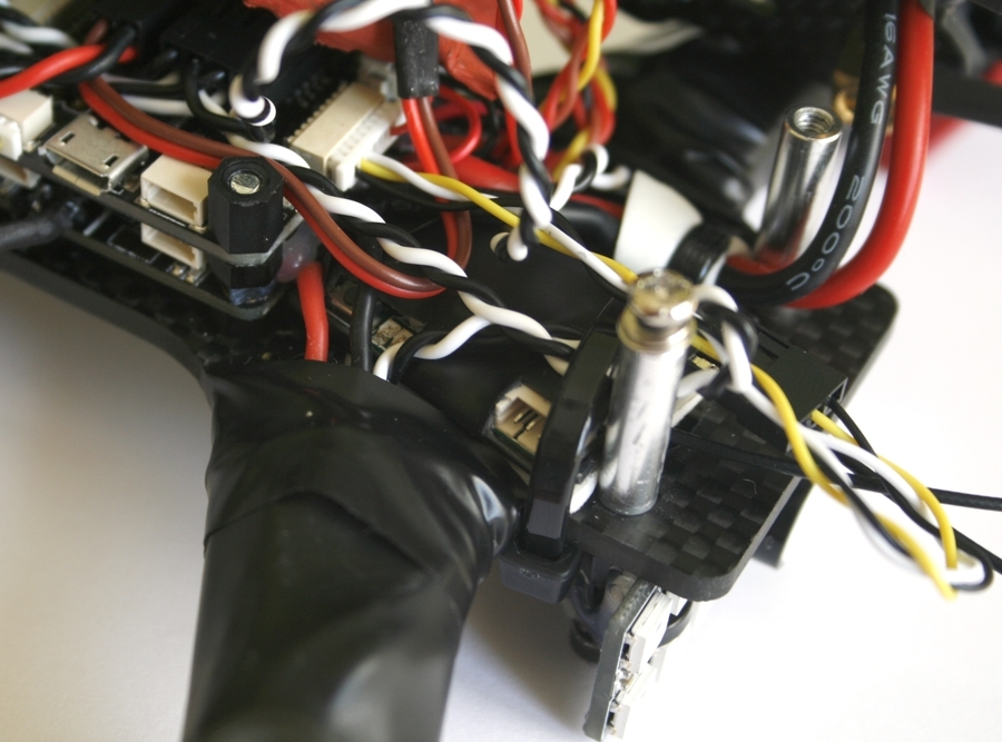
The camera did not fit across the width of the frame side plates. Slightly processed the edges of her board with a file (rather, he cut off the roughness) and she got up without any problems. But the difficulties did not end there. I really liked the quality of the holder for the camera from Diatone, but the camera with it did not fit into the frame in height (about 8-10mm). At first I prikolhozil holder on the outer (upper) side of the plate through a neoprene damper, but the design turned out to be unreliable. Later came the idea of the most simple and reliable fastening. I took only the clamp from the Diatone`s mount and put it on a piece of rod with M3 thread. To prevent the camera from moving sideways, I fixed the yoke with nylon couplings.
I liked very much that only connectors for regulators had to be soldered from the connectors to the PC. I did not fit the full three-pin connectors in height, I had to go to the trick and use two-pin. For the first five channels (4 for regulators + 1 “for every fireman”) I soldered the connectors to the signal area and the “ground”, for the other three - to the “plus” and “ground” so that the PC itself could be powered and already from it - backlight. Given that the Chinese clones of flight controllers sin by unreliable fixation of the USB connector, I lost it too. Another point characteristic of the clone SPRacingF3, is the connector "tweeters". As in the case of vbat, there is a two-contact connector JST-XH on the upper side of the board, and on the lower side it is duplicated by contact pads. The hitch is that the clone "earth" on the connector has a constant and when it is used, the "squeaker" will always be activated. Normal work for the "tweeter" "earth" is derived only on the contact pad. This is easily verified by the tester: the “plus” of the connector is called with the “plus” on the pad, and the “minus” is not called. Therefore, it is necessary to solder the wires for the "pusher" to the underside of the PC.
Three-pin connectors regulators also had to be replaced. It was possible to use four two-pin plugs, but instead, I took two four-pin plugs and inserted all regulators into one “ground”, into the second (observing the order of motor connection) - a signal wire.
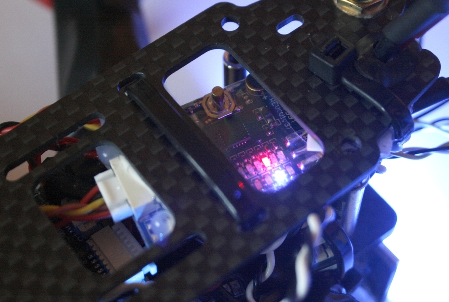
The backlit plate is wider than the frame and protrudes at the sides. The only place where the propellers do not bring her down is under the frame. I had to collective farm: I took long bolts, put nylon sleeves with previously made cuts on them (so that the fasteners fastening the backlight could be fixed) and screwed it through the bottom plate into the frame stands. To the resulting legs with ties, he pulled the plate with the LEDs (the holes in the plate fit perfectly) and filled the ties with hot glue. On the back side of the plate soldered connectors.
Already after the assembly, during the setup stage, it turned out that there was something wrong with the squeaker. Immediately after connecting the battery, it began to squeak monotonously, and if you activate it from the console, then the rhythmic one also superimposed on this monotonous squeak. I first sinned on the PC, but after measuring the voltage with a multimeter, it became clear where exactly the problem was. In fact, it was possible from the very beginning to connect a conventional LED to the tweeter wires. In the end, I ordered several tweeters at once, listened to them and installed the loudest one.
Often the PDB and the controller are attached to the frame with nylon bolts, but I do not trust their strength. Therefore, I used 20mm metal bolts and nylon couplings. After installing the PDB, I soldered the power supply to the regulators (the other wires were soldered in advance) and filled the soldering places with hot melt glue. The main power wire going to the battery was fastened to the frame with a coupler so that it would not be torn out in the event of an accident.
I removed all connectors from the receiver with pliers, except for the required three, and the jumper between the third and fourth channels disappeared directly on the board. As I wrote above, it would be wiser to take the receiver without connectors. I also deployed his antenna and heat-shrink it. On the frame, the receiver fits well between the PBD and the rear pillar. With this arrangement, its indicators are clearly visible and there is access to the bind button.
I fixed the video transmitter with screeds and hot melt adhesive to the top frame plate so that through the slot there was access to the channel switching button and LED indicators.
For mounting the video transmitter antenna in the frame there is a special hole. But do not connect it directly to the transmitter. It turns out a kind of lever, where one antenna serves as one arm, the other with the transmitter itself with all the wires, and the point of attachment of the connector will be the fulcrum at which the load will fall. Thus, in the event of an accident with almost 100% probability, the connector on the transmitter board will break off. Therefore, it is necessary to mount the antenna through some kind of adapter or extension cord.
To MinimOSD, I decided to solder the connectors, not the wires directly. On the forums they write that this board often burns, therefore it makes sense to immediately prepare for a possible replacement. I took the bar with connectors in two rows, bottom soldered to the contact pads with holes, and on the top brought vIn and vOut. After that, he filled the soldering places with hot melt and packed the entire board in shrink.

The final touch is a sticker with a phone number. She will give at least a little hope in case of loss of the quadcopter.

Build on this came to an end. It turned out compact and at the same time saved access to all the necessary controls. More photos can be viewed here.. The quadcopter weight without battery is 330g, with a battery - 470g. And this is still without an action camera and mounting for it. In the next article I will talk about the firmware and setting up the resulting quadcopter.
I described the entire build and configuration process here and here , and below will be a slightly modified version containing more information from my previous articles.
I will leave out the question of entering this hobby and go directly to the quadcopter.
Select quadcopter size
A year ago, quadcopters of the 250th size were the most popular. But now pilots prefer to assemble smaller devices, which is very reasonable: the weight is less, and the power is the same. I chose the 180th size not for some practical reasons, but as a sort of challenge for the assembly.
In fact, this approach to the selection is not quite correct. It is much more reasonable to choose first the size of the propellers, and already under them - the smallest frame, where the chosen propellers fit. And with this approach, the 180th format is generally rejected. Judge for yourself: the 210th format allows you to put the same 5-inch propellers that the 250th, while the quadric itself turns out easier, and the 4-inch propellers fit into the 160th frame. It turns out that the 180th size is such an intermediate format that is “neither ours nor yours”. It can also be considered weighted 160th. But, nevertheless, I chose him. Perhaps because it is the minimum size that is capable of more or less comfortable with a GoPro or Runcam camera.
Accessories
Let's start with the motors. "Intermediate" size of 180, as well as the richness of their range, complicate the choice. On the one hand, you can take what goes on the 160th, on the other - what is set on the 210th or even the 250th. It is necessary to proceed from the propellers and the battery (the number of cans). I see no reason to use the 3S battery, but for the propellers, the general rules are:
- you need maximum static thrust - increase the diameter of the propeller and reduce the pitch (within reasonable limits)
- need high speed - reduce the diameter and increase the step (within reasonable limits)
- need a high thrust with a small diameter - add the number of blades (again, within reasonable limits, because if the difference between two-and three-bladed propellers is noticeable, then between three and four-blades is not so big)
In my case, I have a 4 inch propeller size limit, but I have no motor limit. So, the three-blade 4045 bullnose propellers would be the most sensible. They are difficult to balance, but with them control is more responsive and predictable, and the sound is quieter. On the other hand, with two-bladed propellers, the speed of a quadrocopter is higher, but I don’t really need it. “Among the people” in the 180s frames the following setups predominate:
- lightweight with 1306-3100KV motors, conventional 4045 propellers and 850mAh battery
- heavy and powerful for three-bladed bullnose propellers and an action camera with 2205-2600KV motors and 1300mAh battery
In fact, the frame allows you to put the motors from 1306-4000KV to 22XX-2700KV. By the way, I don’t know why, but the 1806-2300KV motors are now in disgrace and are little used.
For my quadric motors, I took - RCX H2205 2633KV . First, I wanted to have a reserve of power (although with my modest piloting skills, it is not clear why). Secondly, my setups have never been super-light, in addition, I also plan to carry an action camera. Specifically RCX motors - a compromise option. They are cheap, but there are a lot of quality complaints. At the time of purchase of components, it was one of the few 2205-2600KV motors on the market. Now (at the time of this writing) the range is much larger and it is better to choose something else.
With the rest of the components acted on the principle of "more challenge":
- Frame RC180 V2 . Inexpensive (branded counterparts are 2-3 times more expensive), lightweight, with a good line up and 3mm bottom plate. Unfortunately, we cannot buy spare parts for it separately, but considering the price of the entire frame, it is quite possible to buy 1-2 sets for spare parts.
- Receiver FrSky D4R-II . At first, I wanted to try FrSky X4R-SB, but in this case I would have to change the module on the transmitter, but I didn’t want to do this at all. Looking ahead I will say that it is wiser to take the version of the receiver without soldered connectors. At home, I still soldered them.
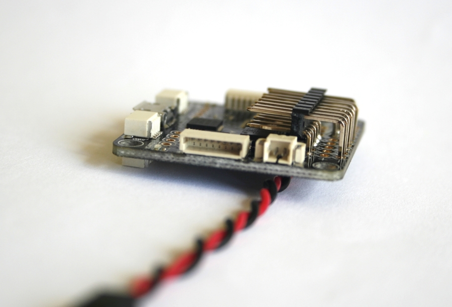
- The FVT LittleBee 20A regulators are inexpensive and proven, but are now outdated. When I bought them just appeared on sale FVT LittleBee 20A PRO on the Silabs F396 chip (the version that I use the Silabs F330 chip), and at the time of this writing, pre-orders for the FVT LittleBee 20A-S, sharpened under BLHeli_S, were already taken. Here you can read about the technical side of the regulators LittleBee 20A.
- Foxeer FX799T Video Transmitter - compact, popular and with a microphone.
- Camera the Sony HAD the Super-CCD 600TVL (the IR Block, the NTSC, objective 2.8). It was possible and Foxeer XAT600M , but I need no body.
- Diatone Camera Holder .
- Antenna- "clover" BeeRotor and extension cable .
- MICRO MinimOSD .
- Included with the frame is already a power distribution board, but I do not want to use it. Therefore, I ordered the Matek Mini Power Hub , it is much more convenient. By the way, when using 3S batteries, this PBD emits a loud whistle and it cannot be treated.
- Several Turnigy nano-tech 1300mAh 4S 45 ~ 90C batteries .
- Backlight with beeper ZG 12Bit WS2812B LED Board . Later it turned out that the squeaker was either not working, or there were some unknown (no documentation was attached) nuances in the connection. As a result, put another .
- Several sets of propellers DYS 3-blade 4040 Bullnose .
Flight controller selection
You probably noticed that there is no flight controller in the list. I want to describe his choice in more detail. In inexpensive assembly kits often include a CC3D controller, so now it is probably the cheapest PC. Today there is absolutely no point in buying a CC3D. It is outdated and does not have such necessary things as battery charge control and a “squeaker”. His successor, CC3D Revolution, is a completely different product with rich features, but at a price of over 40 €.
Modern flight controllers have already switched from F1 processors to F3, which made Naze32 PCs of the past generation and significantly reduced its price. Now it is truly a national controller, which has almost everything that the soul wants at a price of 12 €.
Of the new generation of PCs, Seriously Pro Racing F3 is the most popular, primarily due to the availability of inexpensive clones. The controller itself is not inferior to Naze32, in addition it has a fast F3 processor, a large amount of memory, three UART ports, an integrated inverter for the S.Bus. It SPRacingF3 Acro I chose. The rest of modern PCs were not considered because of the price, or any specific features (closed firmware, layout, etc.)
I would like to separately note the current trend of combining several boards into one. Most often, PC and OSD or PC and PDB I do not support this idea with a couple of exceptions. I do not want to change the entire flight controller due to a burnt OSD. In addition, as practice shows, sometimes such an association brings problems .
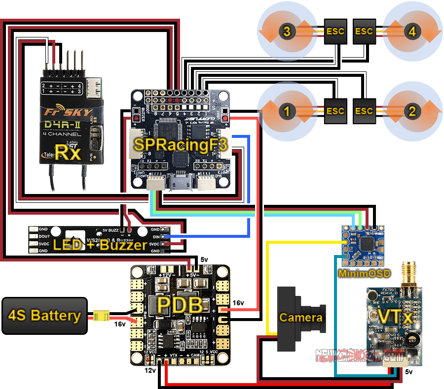
Wiring diagram
It is clear that all components that need power 5V or 12V, will receive it from the BEC `s power distribution board. Theoretically, the camera could be powered directly from 4S-batteries, since the input voltage allows this, but in no case should you do this. Firstly, all cameras are very susceptible to noise in the circuit from the regulators, which will be reflected in the noise in the picture. Secondly, regulators with active braking (such as my LittleBee), with the activation of this braking, give a very serious impulse to the on-board network that can burn the camera. Moreover, the presence of a pulse is directly dependent on the wear of the battery. New ones do not have it, but old ones do. Here is an informative video on the topic of interference from regulators and how to filter them. So it is better to feed the camera either from BEC, or from a video transmitter.
Also, in order to improve the quality of the picture, it is recommended to send not only the signal wire from the camera to the OSD, but also the “ground”. If you twist these wires in a "pigtail", then the "ground" acts as a shield for the signal wire. The truth is in this case, I did not.
If we are talking about the “ground”, then they often argue about whether it is necessary to connect the “ground” from the regulators to the PC or just one signal wire is enough. On the usual racing quadcopter definitely need to connect. Its absence can lead to synchronization failures ( confirmation ).
The final wiring scheme turned out simple and concise, but with a couple of nuances:
- power supply of flight controller (5V) from PDB via controller outputs
- power supply of the radio (5V) from the PC via the OI_1 connector
- video transmitter power (12V) from PDB
- camera power (5V) from the video transmitter
- OSD connected to UART2. Many people use UART1 for this, but like on Naze32, here this connector is paralleled with USB.
- Vbat is connected to PC, not OSD. In theory, battery voltage readings (vbat) can be read either on the OSD or on a PC by connecting the battery to either one or the other. What is the difference? In the first case, the readings will be present only on the monitor or glasses and the PC will not know anything about them. In the second case, the PC can monitor the battery voltage, inform the pilot about it (for example, a “beeper”), and also transmit this data to the OSD, to the “black box” and via telemetry to the console. Adjusting the accuracy of the readings is also easier through the PC. That is, connecting vbat to the flight controller is much preferable.
Assembly
First, a few general assembly tips:
- Carbon conducts current. So everything must be well isolated, so that nowhere does nothing close to the frame.
- Everything that extends beyond the frame, in case of an accident, is likely to be broken or torn off. In this case, we are talking primarily about connectors. Wires can also be chopped with a screw, so that they should be hidden.
- After soldering, it is highly desirable to cover all boards with PLASTIK 71 insulating varnish, and in several layers. From my own experience I will say that applying a liquid brush paint is much more convenient than coating with a spray.
- It will not be superfluous to drop a bit of hot melt onto the soldering points of the wires to the boards. This will protect the solder from vibrations.
- For all threaded connections, it is advisable to use an Loktite medium fixation (blue).
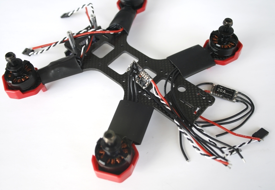
I prefer to start assembly with motors and regulators. Here is a good video on the assembly of a small quadrocopter, from which I adopted the idea of the location of the wires of the motors.
Separately, I want to say about the fastening of regulators: where and how? They can be mounted on and under the beam. I chose the first option, as it seems to me that in this position the regulator is more protected (these are my conjectures, not confirmed by practice). In addition, when mounted on the beam, the regulator is perfectly cooled by air from the propeller. Now how to fix the regulator. Many ways, the most popular - double-sided tape + one or two screeds. “Cheap and angry,” besides dismantling the difficulties will not deliver. Worse, with such a mount you can damage the regulator board (if you put a tie on it) or wires (if you attach them). So I decided to mount the regulators with a shrink tube (25mm) and sealed them together with the rays. There is one caveat: the regulator itself must also be in heat shrinkage (mine was sold in it),
It also makes sense to glue on a piece of double-sided tape the bottom of each beam at the place of attachment of the motor. First, it will protect the motor bearing from dust. Secondly, if for some reason one of the bolts is unscrewed, it will not fall out during flight and will not be lost.
When assembling the frame did not use a single bolt from the kit, since they are all indecently short. Instead, I got a little longer and with a Phillips screwdriver head (there is such a personal preference).
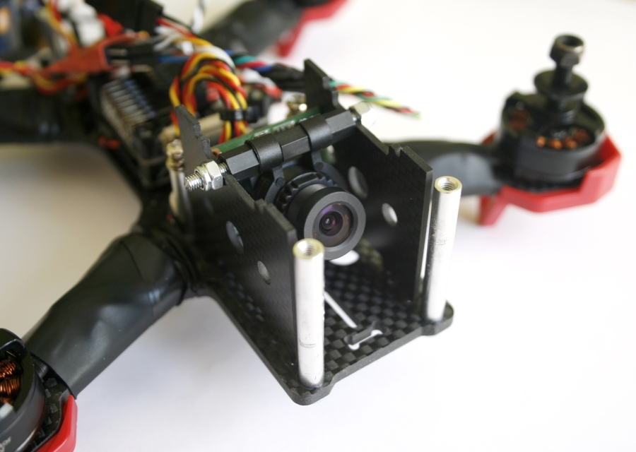
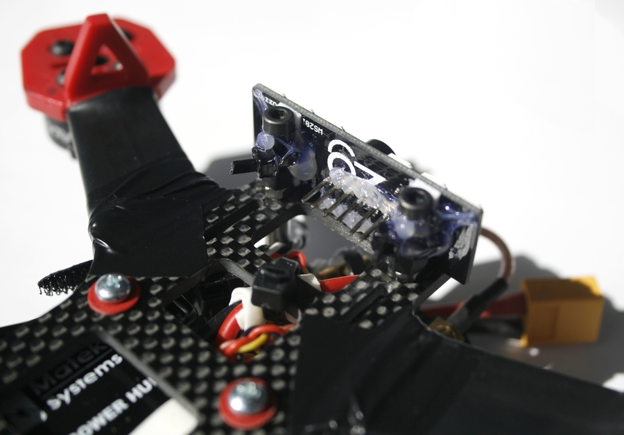
The camera did not fit across the width of the frame side plates. Slightly processed the edges of her board with a file (rather, he cut off the roughness) and she got up without any problems. But the difficulties did not end there. I really liked the quality of the holder for the camera from Diatone, but the camera with it did not fit into the frame in height (about 8-10mm). At first I prikolhozil holder on the outer (upper) side of the plate through a neoprene damper, but the design turned out to be unreliable. Later came the idea of the most simple and reliable fastening. I took only the clamp from the Diatone`s mount and put it on a piece of rod with M3 thread. To prevent the camera from moving sideways, I fixed the yoke with nylon couplings.
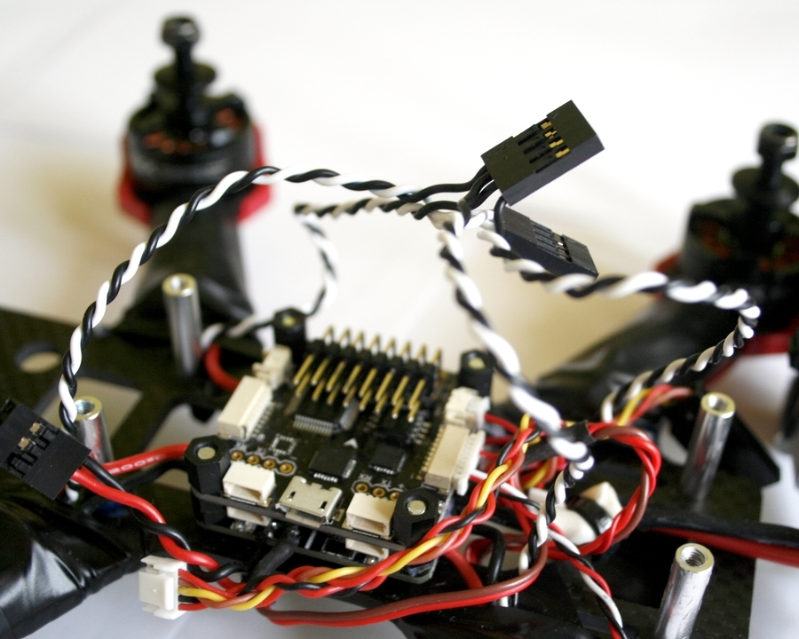
I liked very much that only connectors for regulators had to be soldered from the connectors to the PC. I did not fit the full three-pin connectors in height, I had to go to the trick and use two-pin. For the first five channels (4 for regulators + 1 “for every fireman”) I soldered the connectors to the signal area and the “ground”, for the other three - to the “plus” and “ground” so that the PC itself could be powered and already from it - backlight. Given that the Chinese clones of flight controllers sin by unreliable fixation of the USB connector, I lost it too. Another point characteristic of the clone SPRacingF3, is the connector "tweeters". As in the case of vbat, there is a two-contact connector JST-XH on the upper side of the board, and on the lower side it is duplicated by contact pads. The hitch is that the clone "earth" on the connector has a constant and when it is used, the "squeaker" will always be activated. Normal work for the "tweeter" "earth" is derived only on the contact pad. This is easily verified by the tester: the “plus” of the connector is called with the “plus” on the pad, and the “minus” is not called. Therefore, it is necessary to solder the wires for the "pusher" to the underside of the PC.
Three-pin connectors regulators also had to be replaced. It was possible to use four two-pin plugs, but instead, I took two four-pin plugs and inserted all regulators into one “ground”, into the second (observing the order of motor connection) - a signal wire.
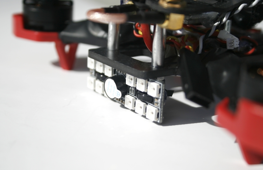
The backlit plate is wider than the frame and protrudes at the sides. The only place where the propellers do not bring her down is under the frame. I had to collective farm: I took long bolts, put nylon sleeves with previously made cuts on them (so that the fasteners fastening the backlight could be fixed) and screwed it through the bottom plate into the frame stands. To the resulting legs with ties, he pulled the plate with the LEDs (the holes in the plate fit perfectly) and filled the ties with hot glue. On the back side of the plate soldered connectors.
Already after the assembly, during the setup stage, it turned out that there was something wrong with the squeaker. Immediately after connecting the battery, it began to squeak monotonously, and if you activate it from the console, then the rhythmic one also superimposed on this monotonous squeak. I first sinned on the PC, but after measuring the voltage with a multimeter, it became clear where exactly the problem was. In fact, it was possible from the very beginning to connect a conventional LED to the tweeter wires. In the end, I ordered several tweeters at once, listened to them and installed the loudest one.
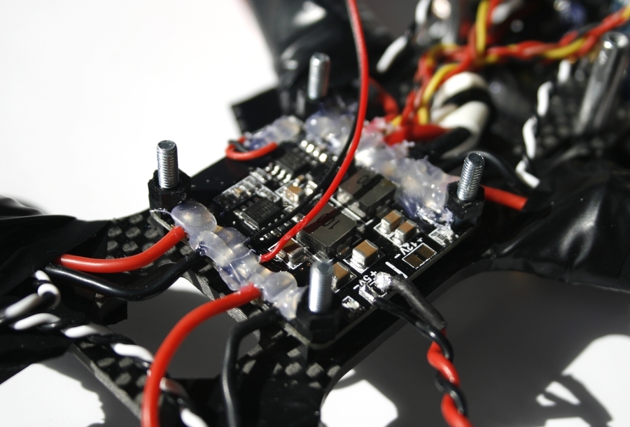
Often the PDB and the controller are attached to the frame with nylon bolts, but I do not trust their strength. Therefore, I used 20mm metal bolts and nylon couplings. After installing the PDB, I soldered the power supply to the regulators (the other wires were soldered in advance) and filled the soldering places with hot melt glue. The main power wire going to the battery was fastened to the frame with a coupler so that it would not be torn out in the event of an accident.
I removed all connectors from the receiver with pliers, except for the required three, and the jumper between the third and fourth channels disappeared directly on the board. As I wrote above, it would be wiser to take the receiver without connectors. I also deployed his antenna and heat-shrink it. On the frame, the receiver fits well between the PBD and the rear pillar. With this arrangement, its indicators are clearly visible and there is access to the bind button.
I fixed the video transmitter with screeds and hot melt adhesive to the top frame plate so that through the slot there was access to the channel switching button and LED indicators.
For mounting the video transmitter antenna in the frame there is a special hole. But do not connect it directly to the transmitter. It turns out a kind of lever, where one antenna serves as one arm, the other with the transmitter itself with all the wires, and the point of attachment of the connector will be the fulcrum at which the load will fall. Thus, in the event of an accident with almost 100% probability, the connector on the transmitter board will break off. Therefore, it is necessary to mount the antenna through some kind of adapter or extension cord.
To MinimOSD, I decided to solder the connectors, not the wires directly. On the forums they write that this board often burns, therefore it makes sense to immediately prepare for a possible replacement. I took the bar with connectors in two rows, bottom soldered to the contact pads with holes, and on the top brought vIn and vOut. After that, he filled the soldering places with hot melt and packed the entire board in shrink.
The final touch is a sticker with a phone number. She will give at least a little hope in case of loss of the quadcopter.
Build on this came to an end. It turned out compact and at the same time saved access to all the necessary controls. More photos can be viewed here.. The quadcopter weight without battery is 330g, with a battery - 470g. And this is still without an action camera and mounting for it. In the next article I will talk about the firmware and setting up the resulting quadcopter.