We do the expansion module for Raspberry Pi with Arduino onboard
In our hakspeyse there are many different Raspberry Pi, by which we teach children to program in python, to make robots and various useful gadgets. Of course, doing the same thing on the Arduino. For three years of living in perfect harmony with these extremely different platforms, we have a few ideas about how to properly make a training robot, given the pros and cons of each piece of iron. All these thoughts materialized in the new device, which will be discussed further.
In fact, we designed the Arduino-compatible expansion module for RPi, which contains a motor driver and a power conditioner. It is clear that this module is a self-sufficient controller for the training robot, but it is the RPi + Arduino sandwich that demonstrates the ideologically correct approach to creating robots. What this thing looks like, what characteristics it possesses, and where it can be applied read further.
A bit of history
4 years have already passed since the release of the Raspberry Pi Model B series. At one time, it was the hype around RPi that partly led us to create our hackspace. After all, the first thing we started to do was to teach children robotics at RPi. After the first lessons with high school students on the basis of the Ural computer school named after N.N. Krasovsky, we thought about our laboratory workshop, open to all sufferers.
Our lessons have developed in the basic course, which was later adapted to the Arduino. The continuation of this course should have been specific projects in which children could apply their knowledge of the work of microcontrollers and various useful components. We have devoted a whole class of such educational projects to the creation of mobile robots, both on the basis of the Raspberry Pi and on the Arduino.
Our first robot based on RPi was created as a guide for working with schoolchildren. It was a two-wheeled robot, where the guys worked out work with engines and various kinds of sensors, in preparation for competitions. The tamiya gearmotor was used as a chassis. Engine driver served drv8833 from TI. In the variant for the LineFollower robot there were two self-made reflection sensors. On the upper deck of the robot was installed bezdeechnaya breadboard for 400 points.
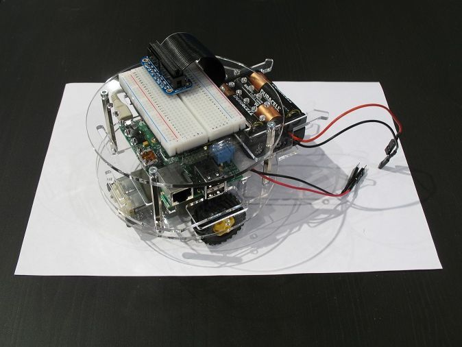
The robot proved to be excellent, so over time the platform tried on a different body kit. In addition to LineFollower, which we by the way call tracker in our fashion, the robot wore optical reflection sensors, ultrasonic range finders, drew a marker on whatman paper, finally controlled via wifi, transferring the image from the webcam.
Over time, it came to the realization that the gear motor was chosen not the most popular, but also very noisy. The body of the robot did not accommodate all the hotelok, and was not compatible with common designers. And most importantly, the idea to make an extension module for RPi, which would save the robot from unnecessary "routine" communications and devices. Thus began the project of a wheeled robot codenamed MR-K-1, and after it the MR-K-2. From the very beginning we began to provide landing holes for both platforms, and below is a model of a robot with an Arduino on board.
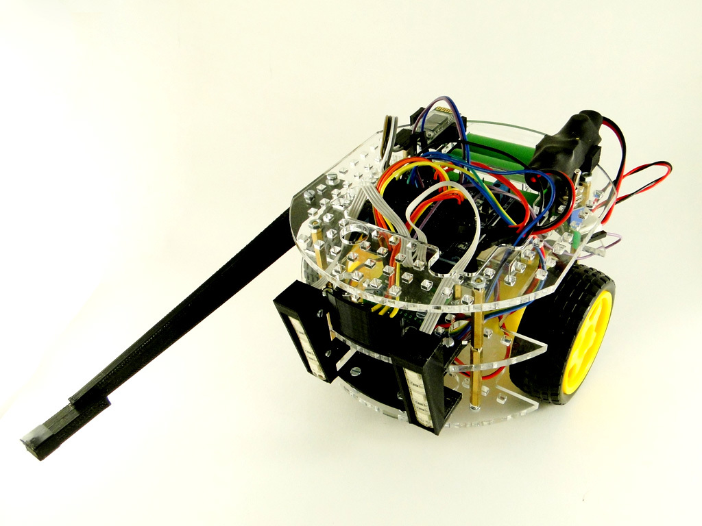
This is a modification for the battle, in which schoolchildren, controlling a robot via bluetooth, strive to burst balloons attached to an enemy machine. The frame was increased, the gear motor was replaced with the common Chinese engine of yellow (and sometimes white) color. The case was adapted for the multiplo constructor, so now it is covered with square holes. All this took several weeks. But the work on the expansion module was a bit long. And the problem was not so much the complexity of implementation, as in the lack of time, aggravated by perfectionism :)
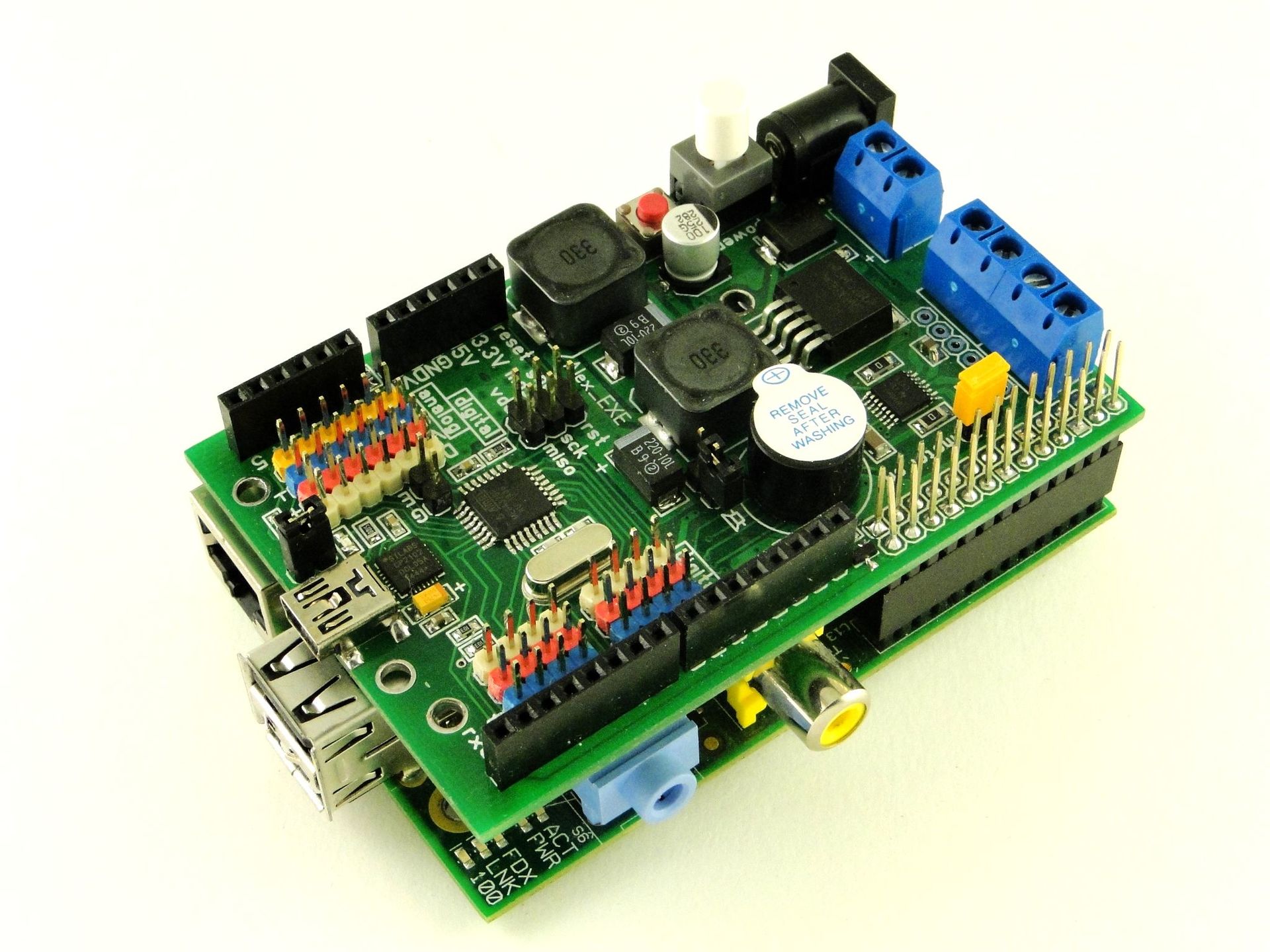
Expansion Module RPiDuino
The main developer of the module was Alexander Vasiliev, the leading extremely useful blog alex-exe.ru. By the time the project started, he already had vast experience in the development of engine drivers, power stabilizers, and many other devices that are interesting for robot building. It was decided to call the board to be called RPiDuino, for it was supposed to provide a symbiosis of Raspberry Pi and Arduino.
So, what we decided to place on the board.
The module was supposed to take direct control of the motor driver, servo drives, and sensors. All this suggests the presence of a microcontroller. And since we are doing a learning robot and this controller should be easily stitched by our students, the choice fell on the well-known atmega328 with the arduino-downloader on board. The presence of atmega makes the module a self-sufficient controller for controlling small training robots.
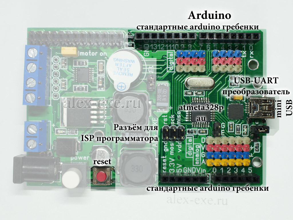
Once an atmega appeared on the board, we also needed a USB-UART bridge, which we used as the CP2102. Another sign of Arduino compatibility is the familiar connectors on the sides of the board, allowing the expansion modules to fit on top.
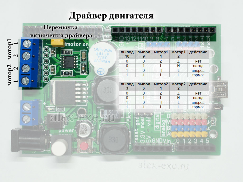
The module must control the engines, so the appropriate driver appeared. Modern drivers have become completely microscopic in size, so that they can easily fit on the board without much damage to the neighboring components. We chose Pololu DRV8833, as there was already some experience with them. Two-channel driver, with a working channel current - 1A.
Finally, a voltage regulator was simply necessary on the board. Initially it was supposed to make separate power supply for the computational part and for servo drives, but we had some minor problems with the layout. So there is only one stabilizer LM2596 that feeds the RPi, the microcontroller, the logical part of the engine driver and the sensors.
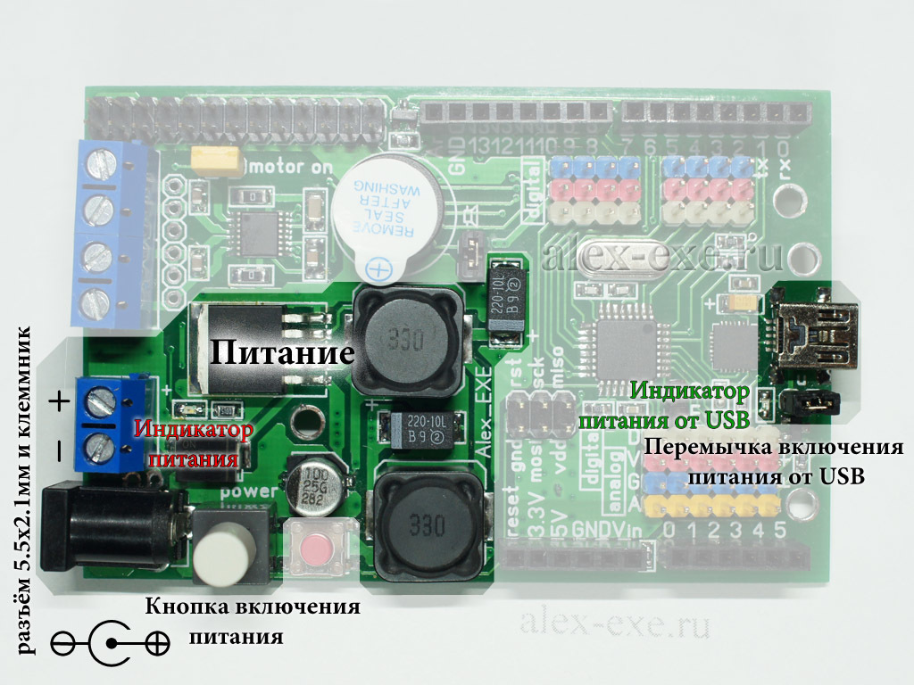
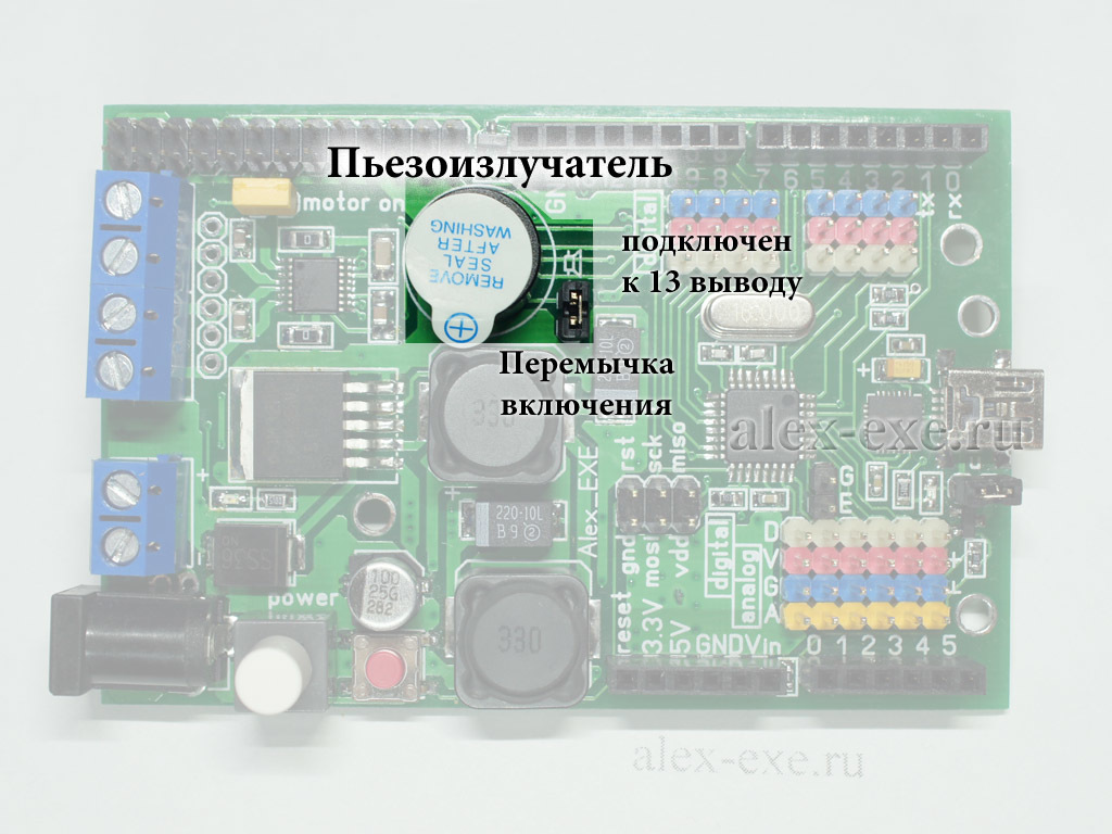
Also, the power switching button and the buzzer have found their place on the board, with the help of the latter the robot complains about its problems.
RPiDuino is inserted into the GPIO connector of the Raspberry Pi, like all modules similar to it. Communication atmega328 and RPi is carried out through the UART.
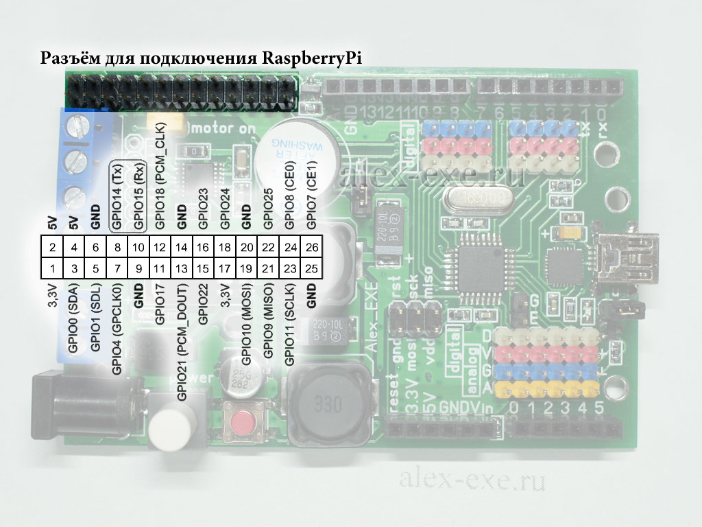
The rest of the GPIO legs are pulled through so that they can be used at your discretion.
Table of key characteristics RPiDuino
Remote-controlled robot based on the RPi + RPiDuino
A remote-controlled robot is a good demonstration of the capabilities of the RPi. It can show the coordinated work of RPi and Arduino, where the older platform is engaged in video signal processing and the user interface, while the second performs its routine robot tasks.
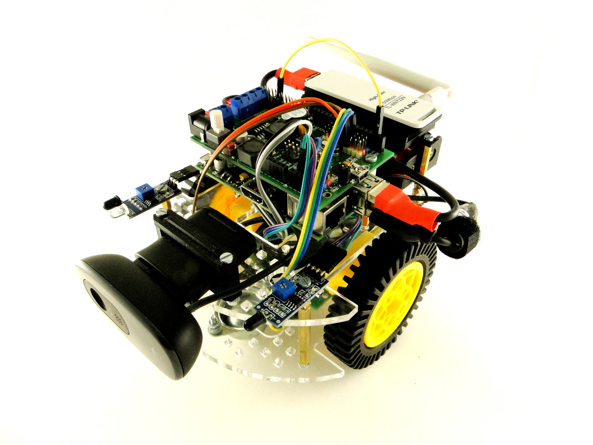
Now on the robot is a webcam with hardware support for mjpg compression, connected to Raspberry via USB. The robot clings to WiFi via the TL-WN722N USB router. Engines are reinforced, with a ratio of 1: 120. The wheels are large with soft rubber to cling to the linoleum in our hackspace. Encoders on the engines help to level the spread in the engines. It all feeds on two LiIon 18650 batteries.
How it all works
On RPiDuino, a program is spinning, which listens to commands from the UART for movement and sends back some telemetry. In my projects I use the SerialFlow library written for my first quadcopter. The program code for RPiDuino can also be found on github.
On the Raspberry Pi side, things are a bit more complicated. First, the robot is controlled via a web interface, so I had to raise a small python web server. The control screen has arrows for setting the direction of motion, a speed controller, telemetry, and a window for displaying the stream from the webcam. For video transmission, I traditionally use mjpg-streamer.
If you want to repeat something similar in your robot, the installation algorithm will be as follows.
1) Install mjpg-streamer, and set up the transmission of the video stream to http.
2) Install the pyserial package.
3) Download and unpack the archive with the server part of the control program.
4) Fill the control sketch with RPIDuino.
5) Configure wifi on RPi.
6) Configure autorun control program on RPi.
RPiDuino and ROS
Another reason why we need this expansion module is the opportunity to show our students the correct concept of robots. Now it sounds like this: “Look, guys, the robot has a main computer that manages complex calculations. It can recognize images, build a map using lidar and SLAM. All this takes him a lot of resources, so that he can no longer control the wheels of the ground robot, and God forbid, by stabilizing the quadrocopter in flight. For these operations, there is another computer at the level of the spinal cord that specializes in specific simple tasks and is not distracted by anything else. These two computers are connected by a data bus, over which they communicate with each other and other modules. ”
This is where the concept of ROS comes up. In this case, the core of the system is spinning on RPi, and RPiDuino is the ROS node. By the way, we have already made a small package for managing RPIDuino via ROS. Soon we will publish a separate article on this topic.
What's next?
Beta version of the module proved to be worthy. Now a small number of boards can be obtained in our hackspace , write to the person who is interested. We are planning to create the next version, with new engine drivers, with an additional display and some other buns. Sources of fees will certainly be published. We will be glad to any criticism and participation!
In fact, we designed the Arduino-compatible expansion module for RPi, which contains a motor driver and a power conditioner. It is clear that this module is a self-sufficient controller for the training robot, but it is the RPi + Arduino sandwich that demonstrates the ideologically correct approach to creating robots. What this thing looks like, what characteristics it possesses, and where it can be applied read further.
A bit of history
4 years have already passed since the release of the Raspberry Pi Model B series. At one time, it was the hype around RPi that partly led us to create our hackspace. After all, the first thing we started to do was to teach children robotics at RPi. After the first lessons with high school students on the basis of the Ural computer school named after N.N. Krasovsky, we thought about our laboratory workshop, open to all sufferers.
Our lessons have developed in the basic course, which was later adapted to the Arduino. The continuation of this course should have been specific projects in which children could apply their knowledge of the work of microcontrollers and various useful components. We have devoted a whole class of such educational projects to the creation of mobile robots, both on the basis of the Raspberry Pi and on the Arduino.
Our first robot based on RPi was created as a guide for working with schoolchildren. It was a two-wheeled robot, where the guys worked out work with engines and various kinds of sensors, in preparation for competitions. The tamiya gearmotor was used as a chassis. Engine driver served drv8833 from TI. In the variant for the LineFollower robot there were two self-made reflection sensors. On the upper deck of the robot was installed bezdeechnaya breadboard for 400 points.
The robot proved to be excellent, so over time the platform tried on a different body kit. In addition to LineFollower, which we by the way call tracker in our fashion, the robot wore optical reflection sensors, ultrasonic range finders, drew a marker on whatman paper, finally controlled via wifi, transferring the image from the webcam.
Over time, it came to the realization that the gear motor was chosen not the most popular, but also very noisy. The body of the robot did not accommodate all the hotelok, and was not compatible with common designers. And most importantly, the idea to make an extension module for RPi, which would save the robot from unnecessary "routine" communications and devices. Thus began the project of a wheeled robot codenamed MR-K-1, and after it the MR-K-2. From the very beginning we began to provide landing holes for both platforms, and below is a model of a robot with an Arduino on board.
This is a modification for the battle, in which schoolchildren, controlling a robot via bluetooth, strive to burst balloons attached to an enemy machine. The frame was increased, the gear motor was replaced with the common Chinese engine of yellow (and sometimes white) color. The case was adapted for the multiplo constructor, so now it is covered with square holes. All this took several weeks. But the work on the expansion module was a bit long. And the problem was not so much the complexity of implementation, as in the lack of time, aggravated by perfectionism :)
Expansion Module RPiDuino
The main developer of the module was Alexander Vasiliev, the leading extremely useful blog alex-exe.ru. By the time the project started, he already had vast experience in the development of engine drivers, power stabilizers, and many other devices that are interesting for robot building. It was decided to call the board to be called RPiDuino, for it was supposed to provide a symbiosis of Raspberry Pi and Arduino.
So, what we decided to place on the board.
The module was supposed to take direct control of the motor driver, servo drives, and sensors. All this suggests the presence of a microcontroller. And since we are doing a learning robot and this controller should be easily stitched by our students, the choice fell on the well-known atmega328 with the arduino-downloader on board. The presence of atmega makes the module a self-sufficient controller for controlling small training robots.
Once an atmega appeared on the board, we also needed a USB-UART bridge, which we used as the CP2102. Another sign of Arduino compatibility is the familiar connectors on the sides of the board, allowing the expansion modules to fit on top.
The module must control the engines, so the appropriate driver appeared. Modern drivers have become completely microscopic in size, so that they can easily fit on the board without much damage to the neighboring components. We chose Pololu DRV8833, as there was already some experience with them. Two-channel driver, with a working channel current - 1A.
Finally, a voltage regulator was simply necessary on the board. Initially it was supposed to make separate power supply for the computational part and for servo drives, but we had some minor problems with the layout. So there is only one stabilizer LM2596 that feeds the RPi, the microcontroller, the logical part of the engine driver and the sensors.
Also, the power switching button and the buzzer have found their place on the board, with the help of the latter the robot complains about its problems.
RPiDuino is inserted into the GPIO connector of the Raspberry Pi, like all modules similar to it. Communication atmega328 and RPi is carried out through the UART.
The rest of the GPIO legs are pulled through so that they can be used at your discretion.
Table of key characteristics RPiDuino
| Nutrition | |
| Supply voltage | 7.5-24V (without engine driver) 7.5-10.5V (with engine driver) |
| Input current | From 0.5 to 4A, depends on the load, voltage, motor driver |
| Voltage regulator | |
| Output voltage | 5B |
| Output current: working / maximum / peak | 1.5A / 2A / 3A |
| Output voltage ripple | one% |
| Power connector | 5.5x2.1mm and terminal strip |
| Engine driver | |
| Supply voltage | 2.7-10.5V |
| Current per channel worker / peak | 1A / 2A |
| PWM frequency | 50kHz |
| Dimensions | |
| Dimensions | 85x56x22mm 85x56x33mm (with connector for RaspberryPi) |
| Weight | 49g |
Remote-controlled robot based on the RPi + RPiDuino
A remote-controlled robot is a good demonstration of the capabilities of the RPi. It can show the coordinated work of RPi and Arduino, where the older platform is engaged in video signal processing and the user interface, while the second performs its routine robot tasks.
Now on the robot is a webcam with hardware support for mjpg compression, connected to Raspberry via USB. The robot clings to WiFi via the TL-WN722N USB router. Engines are reinforced, with a ratio of 1: 120. The wheels are large with soft rubber to cling to the linoleum in our hackspace. Encoders on the engines help to level the spread in the engines. It all feeds on two LiIon 18650 batteries.
How it all works
On RPiDuino, a program is spinning, which listens to commands from the UART for movement and sends back some telemetry. In my projects I use the SerialFlow library written for my first quadcopter. The program code for RPiDuino can also be found on github.
On the Raspberry Pi side, things are a bit more complicated. First, the robot is controlled via a web interface, so I had to raise a small python web server. The control screen has arrows for setting the direction of motion, a speed controller, telemetry, and a window for displaying the stream from the webcam. For video transmission, I traditionally use mjpg-streamer.
If you want to repeat something similar in your robot, the installation algorithm will be as follows.
1) Install mjpg-streamer, and set up the transmission of the video stream to http.
2) Install the pyserial package.
3) Download and unpack the archive with the server part of the control program.
4) Fill the control sketch with RPIDuino.
5) Configure wifi on RPi.
6) Configure autorun control program on RPi.
RPiDuino and ROS
Another reason why we need this expansion module is the opportunity to show our students the correct concept of robots. Now it sounds like this: “Look, guys, the robot has a main computer that manages complex calculations. It can recognize images, build a map using lidar and SLAM. All this takes him a lot of resources, so that he can no longer control the wheels of the ground robot, and God forbid, by stabilizing the quadrocopter in flight. For these operations, there is another computer at the level of the spinal cord that specializes in specific simple tasks and is not distracted by anything else. These two computers are connected by a data bus, over which they communicate with each other and other modules. ”
This is where the concept of ROS comes up. In this case, the core of the system is spinning on RPi, and RPiDuino is the ROS node. By the way, we have already made a small package for managing RPIDuino via ROS. Soon we will publish a separate article on this topic.
What's next?
Beta version of the module proved to be worthy. Now a small number of boards can be obtained in our hackspace , write to the person who is interested. We are planning to create the next version, with new engine drivers, with an additional display and some other buns. Sources of fees will certainly be published. We will be glad to any criticism and participation!