Homemade Scanning Laser Rangefinder
In this article I will talk about how I did a homemade laser scanning range finder using the triangulation principle of distance measurement, and about the experience of using it on a robot.
Why do you need a scanning distance?
Today there are not so many indoor navigation methods in robotics. Determining the position of the robot in space using a laser scanner is one of them. An important advantage of this method is that it does not require the installation of any lighthouses in the room. Unlike systems that use image recognition from cameras, data processing from a rangefinder is not so resource intensive. But there is a drawback - the complexity, and accordingly, the price of a range finder.
Traditionally, robotics use laser scanners that use the phase or time-of-flight principle to measure the distance to objects. The implementation of these principles requires a rather complicated circuit design and expensive parts, although the characteristics are decent - using these principles, you can achieve a high scanning speed and a long distance measurement distance.
But for home experiments in robotics such scanners are not very suitable - the price for them starts from $ 1000.
Range finders that use the triangulation principle of measuring distance come to the rescue. A range finder of this type first appeared in the Neato robotic vacuum cleaners:
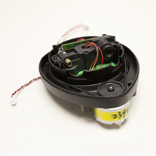
Pretty quickly, amateurs deciphered the protocol of this rangefinder, and began to use it in their projects. Rangefinders themselves as spare parts appeared on ebay in small quantities for about $ 100. After a few years, the Chinese company was able to release the RPLIDAR scanning rangefinder, which was supplied as a complete instrument, not a spare part. Only the price of these rangefinders was quite high - $ 400.
Homemade range finder
As soon as I found out about the Neato range finders, I wanted to collect the very same one. In the end, I succeeded, and I described the assembly process at the Roboforum .
The first version of the rangefinder:
Later, I made another version of the rangefinder, more suitable for use on a real robot, but its quality of work did not fully suit me. It is time for the third version of the rangefinder, and it will be described later.
Device for scanning triangulation laser range finder
The principle of measuring the distance to an object is based on measuring the angle between a laser beam falling on an object and a rangefinder lens. Knowing the distance of the laser-lens (h) and the measured angle, you can calculate the distance to the object - the smaller the angle, the greater the distance.
The principle is well illustrated by a picture from the article :
Thus, the key optical components of such a rangefinder are a laser, an objective lens, and a photoreceiver bar.
Since the range finder is scanning, then all these parts, as well as the control electronics, are mounted on the rotating head.
There may be a question - why do you need to rotate the optics and electronics, because you can install a rotating mirror? The problem is that the accuracy of the rangefinder depends on the distance between the lens and the laser (base distance), so it should be quite large. Accordingly, for a circular scan will need a mirror with a diameter greater than the base distance. A range finder with such a mirror is quite cumbersome.
Scanning head of a range finder with the help of a bearing is fixed on a fixed base. It also fixes the engine, rotating the head. Also in the rangefinder should include an encoder designed to obtain information about the position of the head.
As you can see, the Neato, RPLIDAR range finders and my homemade ones are made according to this scheme.
The most difficult thing in a homemade range finder is the manufacture of the mechanical part. It was her work that caused me the most complaints in the early versions of the rangefinder. The difficulty lies in the manufacture of a scanning head, which must be firmly fixed on the bearing, rotate without a beat and at the same time do not need to transmit electrical signals in any way.
In the second version of the range finder, I solved the first two problems by using parts of the old HDD — the disk itself was used as the base of the scanning head, and the engine on which it was fixed already contained high-quality bearings. At the same time, a third problem arose - electric lines could only be drawn through a small hole in the engine axis. I managed to make a homemade brush unit on 3 lines, fixed in this hole, but the resulting design was noisy and unreliable. In this case, another problem arose - there was no line to forward the encoder signal, and the encoder sensor in this design must be installed on the head, and the encoder disk with marks on the fixed base. The encoder disk was not hard, and this often caused problems.
Photo of the second version of the rangefinder:
Another disadvantage of the resulting rangefinder is the low scanning speed and a sharp drop in accuracy at distances greater than 3m.
I decided to eliminate these shortcomings in the third version of the rangefinder.
Electronics
In principle, the electronic part of the triangulation rangefinder is quite simple and contains only two key components - a light sensitive line and a microcontroller. If there is no problem with choosing a controller, then everything is much more complicated with a ruler. The photosensitive ruler used in such a rangefinder should simultaneously have a sufficiently high light sensitivity, allow the signal to be read at high speed and have small dimensions. The various CCD rulers used in home scanners are usually quite long. The rulers used in barcode scanners are also not the shortest and fastest.
In the first and second versions of the rangefinder, I used the TSL1401 line and its analogue iC-LF1401. These rulers fit well in size, they are cheap, but contain only 128 pixels. For accurate measurement of distances up to 3 meters this is not enough, and only the possibility of sub-image analysis saves.
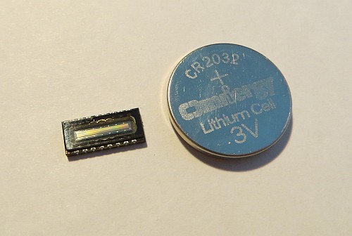
In the third version of the range finder, I decided to use the ELIS-1024 line:
However, it was not easy to buy it. The main suppliers of electronics of these lines simply do not.
The first line that I was able to buy on Taobao turned out to be non-working. The second I bought on Aliexpress (for $ 18), it turned out to be working. Both rulers looked soldered - both had ironed out contacts and, judging by the markings, were made in 2007. And even in the photographs of the majority of Chinese sellers of the line are just like that. It looks like a truly new ELIS-1024 line can only be bought directly from the manufacturer.
The ELIS-1024 photosensitive ruler, as the name suggests, contains 1024 pixels. It has an analog output, and is rather simply controlled.
The DLIS-2K range has even better characteristics. With similar sizes, it contains 2048 pixels and has a digital output. As far as I know, it is used in the Neato rangefinder, and possibly in the RPLIDAR. However, it is very difficult to find it on free sale, even in Chinese stores it doesn’t appear often and is expensive - more than $ 50.
Since I decided to use a ruler with an analog signal output, the rangefinder microcontroller should contain a fairly fast ADC. Therefore, I decided to use a series of controllers - STM32F303, which, at a relatively low cost, have several fast ADCs capable of operating simultaneously.
As a result, I got the following scheme:
The signal from the ruler (pin 10) has a fairly high level of the constant component, and it has to be filtered out using an isolating capacitor.
Further, the signal needs to be strengthened - for this, the AD8061 operational amplifier is used. Far-placed objects give a rather weak signal, so we had to set the gain to 100.
As it turned out as a result of experiments, even in the absence of a signal, at the output of the selected opamp, for some reason, there is always a voltage of about 1.5V, which interferes with the processing of results and impairs the accuracy of measuring the amplitude of the signal. In order to get rid of this bias, I had to apply additional voltage to the inverting input of the op-amp.
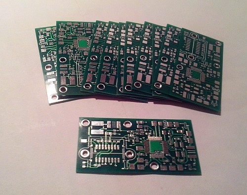
I made a double-sided board, it is quite difficult to make such a board at home, so I ordered the production of boards in China (I had to order 10 pieces at once):
In this rangefinder, I used a cheap M12 threaded lens with a focal length of 16mm. The lens is mounted on a printed circuit board using a ready-made lens holder (these are used in various cameras).
The laser in this rangefinder is an infrared (780 nm) laser module with a power of 3.5 mW.
Initially, I assumed that the laser radiation would need to be modulated, but later it turned out that there was no point in using the ruler used, and therefore the laser is now turned on all the time.
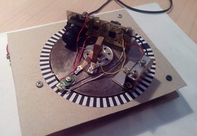
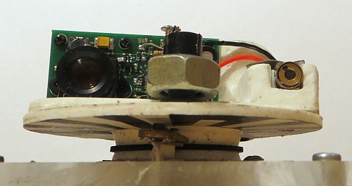
To check the performance of the electronics, this design was assembled, imitating the scanning head of the rangefinder:
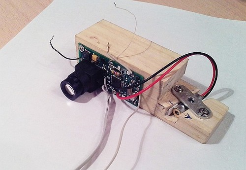
Already in this form, it was possible to verify the accuracy of measuring the distance a rangefinder can provide.
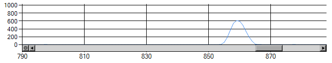
To analyze the signal generated by the ruler, test programs for the microcontroller and PC were written.
An example of the type of signal from the ruler (an object at a distance of 3 m).
Initially, the scheme was not quite the same as above. During the experiments, I had to partially redo the original scheme, so that, as can be seen from the photos, some parts had to be installed by mounting.
Mechanical part
After the electronics have been debugged, it is time to make the mechanical part.
This time I did not bother with the mechanics of the HDD, and decided to make the mechanical parts of liquid plastic, poured into silicone mold. This technology is described in detail on the Internet, including on Giktatimes .
Already after I made the parts, it became clear that it would be easier to make parts on a 3D printer, they could come out harder, and perhaps one piece could be made instead of two. I do not have access to a 3D printer, so I would have to order the production of parts in any company.
Photo of one of the parts of the scanning head of the range finder:
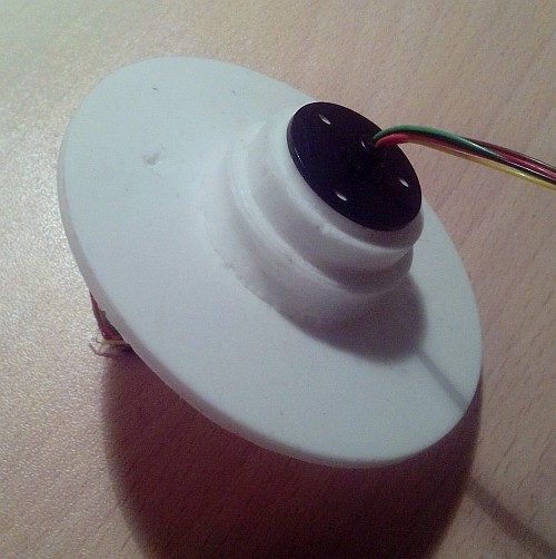
This part is the basis of the head. It consists of a sleeve, on which the bearing is later put on, and a disk. The disk is designed for mounting the second part of the tower, in addition, the encoder disk is glued to it from below.
The sleeve and the disk contain a through hole into which a 6-line brush unit is inserted - it can be seen in the photo. It is the wires that are visible in the photograph that can rotate relative to the body of this node. To increase the stability of the work, 2 pairs of brush lines are used to transmit GND and UART TX signals. The remaining 2 lines are used to transmit the supply voltage and the encoder signal.
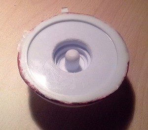
Silicone mold for casting this part:
The second part of the scanning head was made in the same way. It is designed for mounting the circuit board and the laser to the disk. Unfortunately, I have not survived the photographs of the manufacture of this part, so it can only be seen as part of a rangefinder.
A ball bearing is used to attach the scanning head to the base of the range finder. I used a cheap Chinese bearing 6806ZZ. Honestly, I did not like the quality of the bearing - the axis of its inner sleeve could deviate relative to the external axis at a small angle, due to which the rangefinder head also tilts slightly. Mount the bearing to the part with the disk and the base will be shown below.
The base I made of transparent plexiglass 5 mm thick. Bearing, encoder sensor, range finder engine and a small printed circuit board are attached to the base. The base itself is mounted on any suitable surface using racks.
Here is the bottom of the rangefinder base: The
printed circuit board contains an adjustable linear voltage regulator to power the motor, and platforms for connecting the wires of the brush assembly. This also brings the power rangefinder.
As in other rangefinders, the engine rotates the scanning head with the aid of a belt. In order that he did not fall off the sleeve, it has a special recess.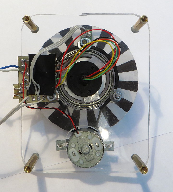
As can be seen from the photo, the bearing is fixed at the base with three screws. On the scanning head, the bearing is held by the protrusion on the sleeve and pressed against it by other screws, simultaneously holding the brush assembly.
The encoder consists of a paper disk with printed risks and an optocoupler with a phototransistor operating in reflection. The optocoupler is fixed with the help of a stand on the base so that the disk plane is next to it:
The signal from the optocoupler through the brush is transmitted to the input of the microcontroller comparator. As the source of the reference voltage for the comparator is the DAC of the microcontroller.
In order for the range finder to determine the position of the zero angle, a long risk is marked on the encoder disk, which marks the zero position of the head (it is visible on the right in the photo above).
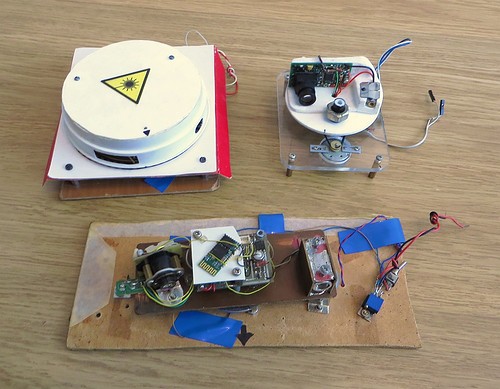
Here is the assembled range finder:
Top view: The
connector at the back of the range finder is used to flash the microcontroller.
To balance the scanning head, a large nut is installed on the front of it — it almost completely eliminates vibration when the head rotates.

The assembled rangefinder must be ustyustirovat - set the laser in such a position that the light reflected from the objects hit the photodetector line. Both plastic parts contain coaxial holes located under the laser groove. Adjustment screws are screwed into the holes, resting against the laser body. By turning these screws, you can change the tilt of the laser.
Observing the shape and amplitude of the received signal in a computer program and changing the laser slope, you need to achieve the maximum signal amplitude.
Also, triangulation range finders require calibration, as I wrote earlier :
In order to use the sensor to measure the distance, it is necessary to calibrate it, i.e. determine the law relating the result returned by the sensor and the actual distance. The calibration process itself is a series of measurements, as a result of which a set of distances from the sensor to an object is formed, and the corresponding results.
In this case, the calibration was a series of measurements of distances to various objects with a homemade range finder and a laser tape measure, after which a regression analysis was performed on the obtained measurement pairs and a mathematical expression was compiled.
The resulting rangefinder has a significant drawback - due to the lack of modulation of the laser radiation, it does not work correctly with any strong illumination. Normal room lighting (even when using a powerful chandelier) does not affect the operation of the rangefinder, but the distance to surfaces directly illuminated by the Sun does not measure the rangefinder correctly. To solve this problem, the rangefinder needs to include an interference filter that transmits light only at a specific wavelength - in this case, 780 nm.
The evolution of homemade range finders:
Overall dimensions of the resulting rangefinder:
Base size: 88x110 mm.
The total height of the rangefinder: 65 mm (can be reduced to 55 while reducing the height of the racks).
Scanning head diameter: 80 mm (like a mini-CD disk).
Like any other triangulation rangefinder, the accuracy of measuring the distance of this rangefinder drops sharply with increasing distance.
When measuring the distance to an object with a reflection coefficient of about 0.7, I had approximately the following accuracy characteristics:
| Distance | Scatter |
|---|---|
| 1m | <1 cm |
| 2 m | 2 cm |
| 5 m | 7 cm |
The cost of manufacturing range finder:
| DIY, $ | Opt., $ | |
|---|---|---|
| Base | ||
| Base plate | 1.00 | 0.50 |
| Engine | 0.00 | 1.00 |
| Bearing | 1.50 | 1.00 |
| Brush knot | 7.50 | 5.00 |
| Fasteners | 0.00 | 2.00 |
| Scan head | ||
| STM32F303CBT6 controller | 5.00 | 4.00 |
| Photo-receiver ruler | 18.00 | 12.00 |
| The rest of the electronics | 4.00 | 3.00 |
| Pay | 1.50 | 0.50 |
| Lens | 2.00 | 1.50 |
| Lens holder | 1.00 | 0.50 |
| Laser | 1.00 | 0.80 |
| Plastic parts | 3.00 | 2.00 |
| Fasteners | 0.00 | 1.00 |
| Assembly | 0.00 | 20.00 |
| Total: | 45.50 | 54.80 |
In the first column - how much the range finder cost me, in the second - how much it could cost in industrial production (the estimate is very approximate).
Rangefinder software
Before writing a program, you need to calculate the clock frequency at which the photodetector line will operate.
In older versions of the rangefinder, the scanning frequency was limited to 3 Hz, in the new rangefinder I decided to make it higher - 6Hz (this was taken into account when choosing a ruler). The range finder makes 360 measurements per revolution, so that at the indicated speed it should be able to perform 2160 measurements per second, that is, one measurement should take less than 460 μs. Each measurement consists of two stages - exposure (accumulation of light with a ruler) and reading data from the ruler. The faster the signal is read out, the longer the exposure time can be, which means that the greater the amplitude of the signal. With a clock frequency of 8 MHz, the read time of 1024 pixels will be 128 μs, at 6 MHz - 170 μs.
At the clock frequency of the microcontroller of the STM32F303 series at 72 MHz, the maximum sampling rate of the ADC is 6 MSPS (with a bit width of 10 bits). Since I wanted to check the operation of the rangefinder at a clock frequency of 8 MHz, I decided to use the ADC operation mode in which two ADCs work simultaneously (Dual ADC mode - Interleaved mode). In this mode, the ADC1 starts up after a signal from an external source, and then, after a configurable time, ADC2:
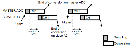
As can be seen from the diagram, the total frequency of ADC samples is two times higher than the trigger frequency (in this case, this is the signal from the TIM1 timer).
At the same time, TIM1 should also generate a clock signal for the photodetector line, synchronous with the ADC samples.
In order to get two signals from one timer with frequencies that differ in two times, you can switch one of the timer channels to TIM_OCMode_Toggle mode, and the second channel should form a normal PWM signal.
Block diagram of the rangefinder program: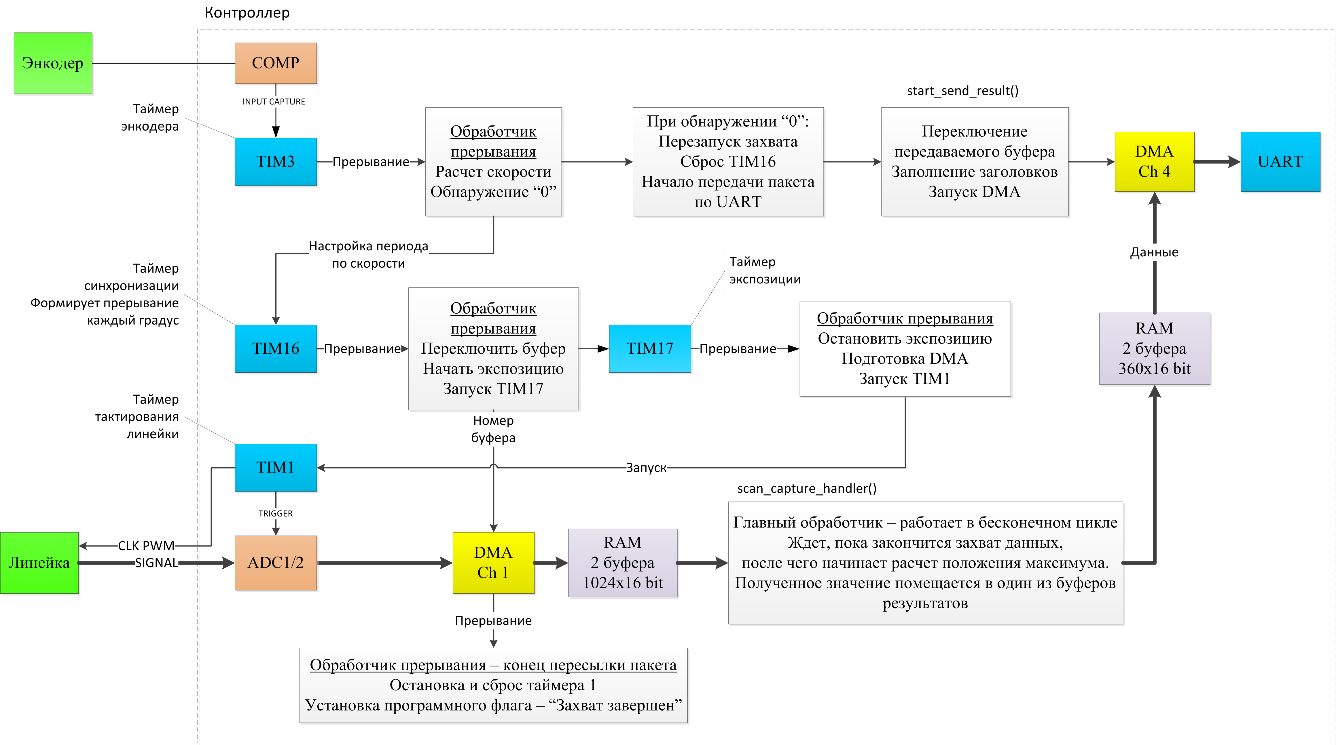
The key part of the program is to capture data from the ruler and control it. As can be seen from the diagram, this process goes at the hardware level, due to the joint work of TIM1, ADC1 / 2 and DMA. To ensure that the exposure time of the ruler is constant, the timer TIM17 is used, operating in Single Pulse mode.
Timer TIM3 generates interrupts when triggered by a comparator connected to an encoder. Due to this, the rotation period of the scanning head of the range finder and its position are calculated. According to the obtained rotation period, the TIM16 timer period is calculated in such a way that it forms interruptions when the head is turned by 1 degree. These interruptions are used to start the exposure of the ruler.
After the DMA transfers all 1024 values captured by the ADC to the memory of the controller, the program starts analyzing these data: first, the maximum position of the signal is searched for to the pixel, then, using the center of gravity search algorithm, with higher accuracy (0.1 pixel ). The resulting value is stored in an array of results. After the scanning head makes a complete revolution, at the time of passage of the zero, this array is transmitted to the UART module using another DMA channel.
Using a range finder
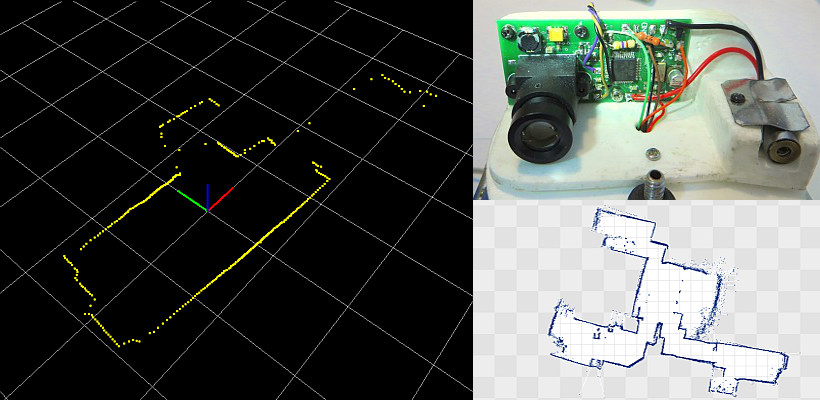
The quality of this rangefinder, like the previous ones, was checked using a self-written program. Below is an example of the image generated by this program as a result of the rangefinder: 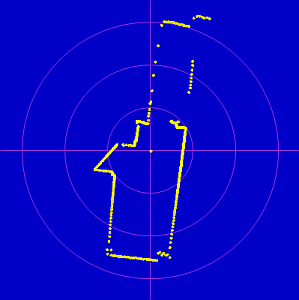
However, the rangefinder was not made just to lie on the table - it was installed on the old Roomba 400 vacuum cleaner instead of the rangefinder of the second version:
The Orange Pi PC computer designed to control robot and communication with him.
As it turned out, due to the large voltage drop on the linear power source of the engine of the rangefinder, the rangefinder requires a supply voltage of 6V to operate at a speed of 6 revolutions per second. Therefore, the Orange Pi and range finder are powered by separate DC-DC converters.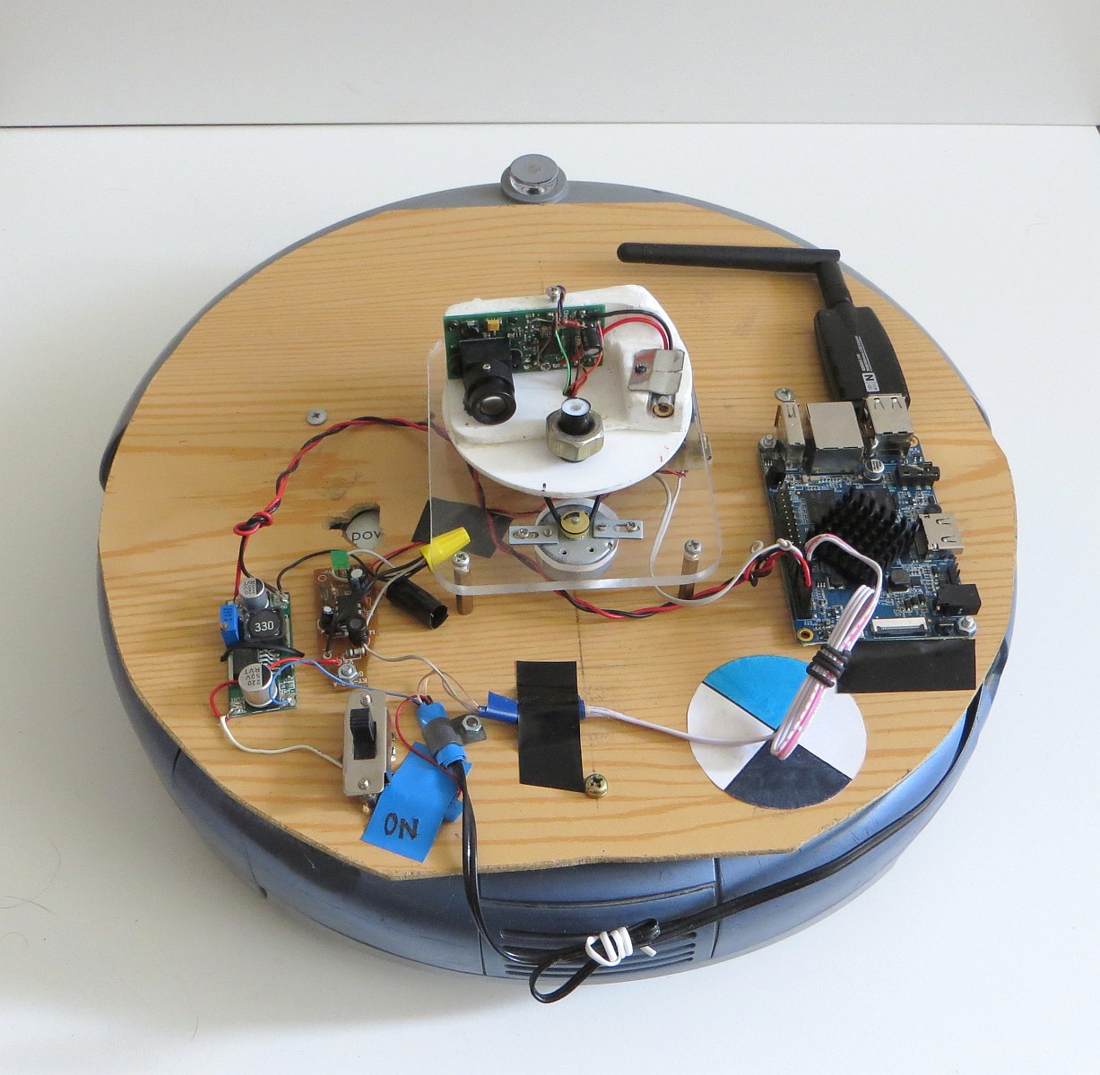
I use ROS to control the robot and analyze data from the range finder .
The data from the rangefinder are processed by a special ROS driver (based on the Neato rangefinder driver), which receives data from the rangefinder using the UART, recalculates them to distances to objects (using calibration data) and publishes them in the standard ROS format.
Here is the information obtained in rviz (ROS data visualization software), the robot is installed on the floor: 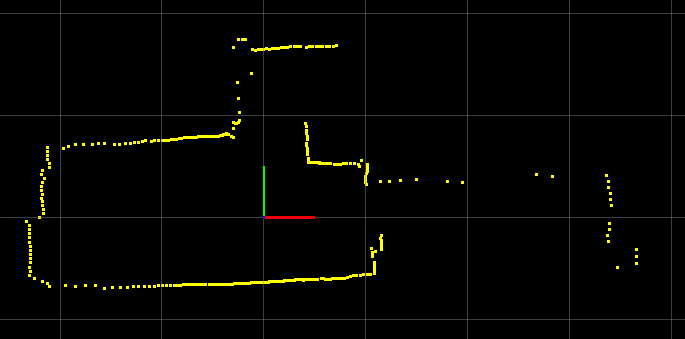
The length of the cell side is 1 meter.
After the data got into ROS, they can be processed using ready-made software packages. In order to build an apartment map, I used hector_slam . For reference: SLAM is a method for simultaneously building a map of a terrain and determining the position of a robot on it.
An example of the resulting apartment map (the form is somewhat unusual, because the range finder "sees" furniture, not walls, and not all rooms are shown):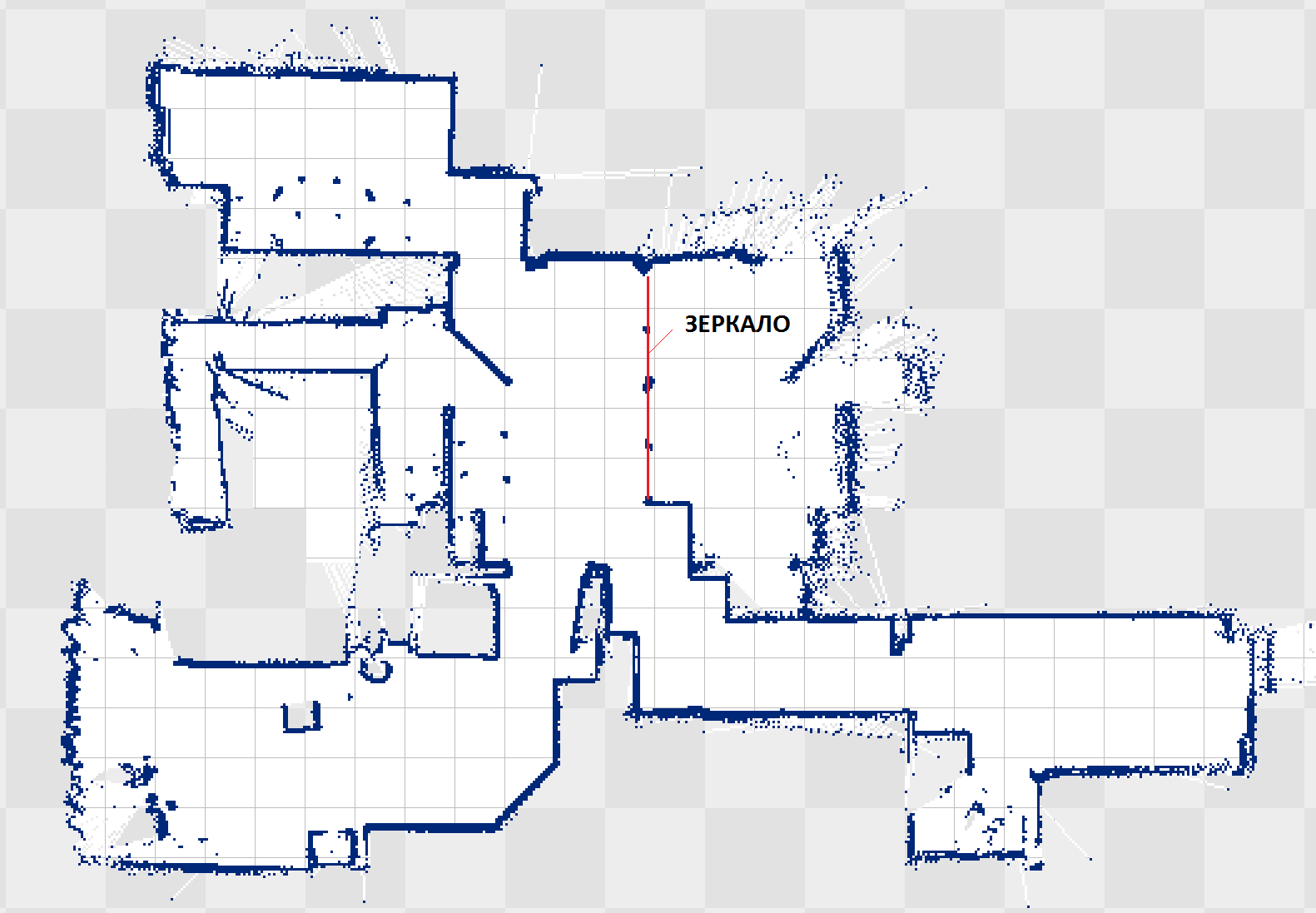
ROS allows you to combine several programs ("nodes" in the terminology of ROS) running on different computers into a single system. Due to this, on Orange Pi you can run only Roomba and rangefinder ROS drivers, and analyze the data and control the robot from another computer. At the same time, experiments showed that hector_slam works normally on Orange Pi, acceptably loading the processor, so it’s quite realistic to organize a fully autonomous operation of the robot.
The SLAM system, thanks to data from the rangefinder, allows the robot to determine its position in space. Using data on the position of the robot and the constructed map, you can organize a navigation system that allows you to "send" the robot to a specified point on the map. ROS contains a software package for this task, but, unfortunately, I could not get it to work properly.
Video of the rangefinder:
More detailed video of building a map using hector_slam:
Source code of the controller program
PS I also have a project of a simpler lidar .