Telemetry for racing. Part 1 - prototype
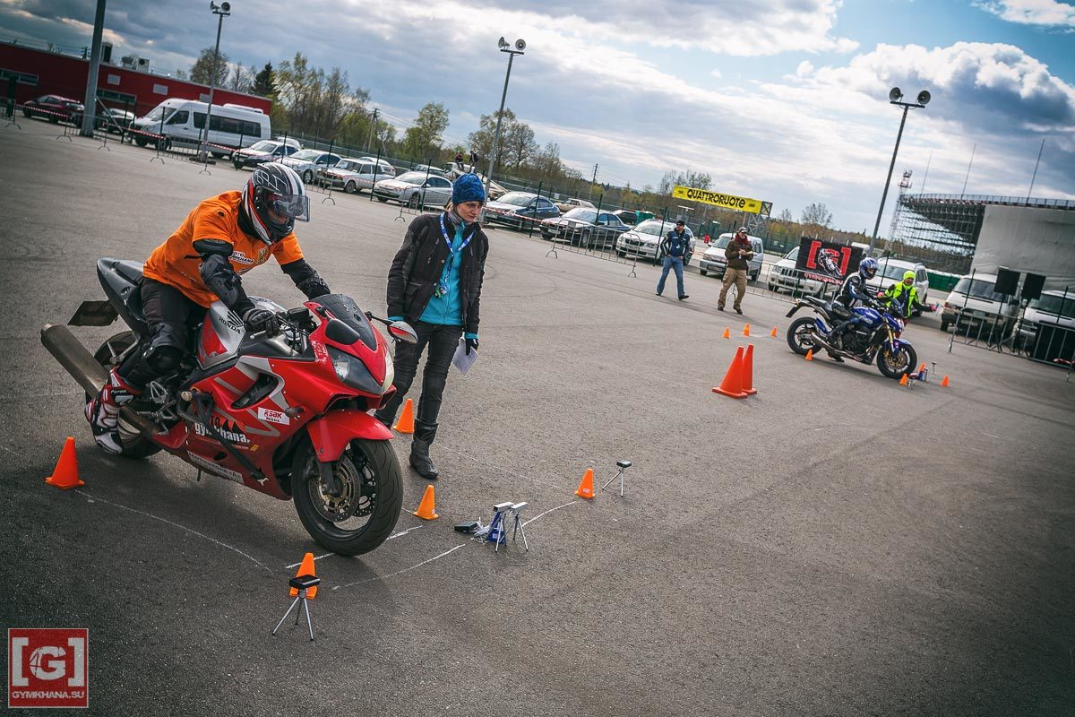
Standing on the training ground at the marked track for motodzhimkhana (a type of motor sport that is gaining popularity), I watched how lap times were measured on a stopwatch on a smartphone. It is clear that accurate data is not obtained. At home, there were several arduins, a couple of displays, and, it would seem, all that was needed to assemble automatic telemetry was to find a pair of suitable sensors that worked when a bike was passing. So began many sleepless nights with a soldering iron, vim, dremel, and sometimes even a grinder.
Looking ahead - everything turned out, the devices successfully worked on all three stages of the moto-jihhane [G] -RSBK championship, and are actively used during training. Collected in the end were:
as well as something else!
The sensors were bought and after half an hour the prototype flashed on the display. True, I was slightly mistaken in the belief that everything else would be enough for me for several evenings.
The article does not have schemes in Fritzing - manuals on connecting sensors and displays on the network is complete, and there are no source codes -(every self-respecting programmer still throws everything out and writes from scratch) I suppose everyone can handle the interval between signals from two inputs. It turned out to be a much more interesting task with the help of available tools and tools to assemble first a prototype in a shoe box suitable for transportation, and later to bring it to near-production form.
At competitions, the race starts from the starting box, which is bounded by cones, and then the drive along the track follows, and the finish line is also to the cones-limited box, located next to the start. Sensors need two - the intersection of the start and the intersection of the finish. So far, it has been decided to note the time directly from the participant’s departure from the box, later on by a traffic light signal, and the sensor can be used to check the false start.
Yes, entertainment adds pair runs on two identical tracks, which means that there should be two sets of equipment.
After examining the range, I found and bought barrier optical beam crossing sensors, consisting of two modules - a radiator and a receiver. A wide range of supply voltage - 6-36V, the signal from the sensor - NPN-output. During tests in the room, they proved to be excellent - a range of several meters, good focusing of the beam, speed of response - within milliseconds.
It is good, now you need to decide how to feed, strengthen and guide them. All IT-shniki know that standards are good, therefore I will feed from 12V, and to fix and guide them - with standard photo supports.
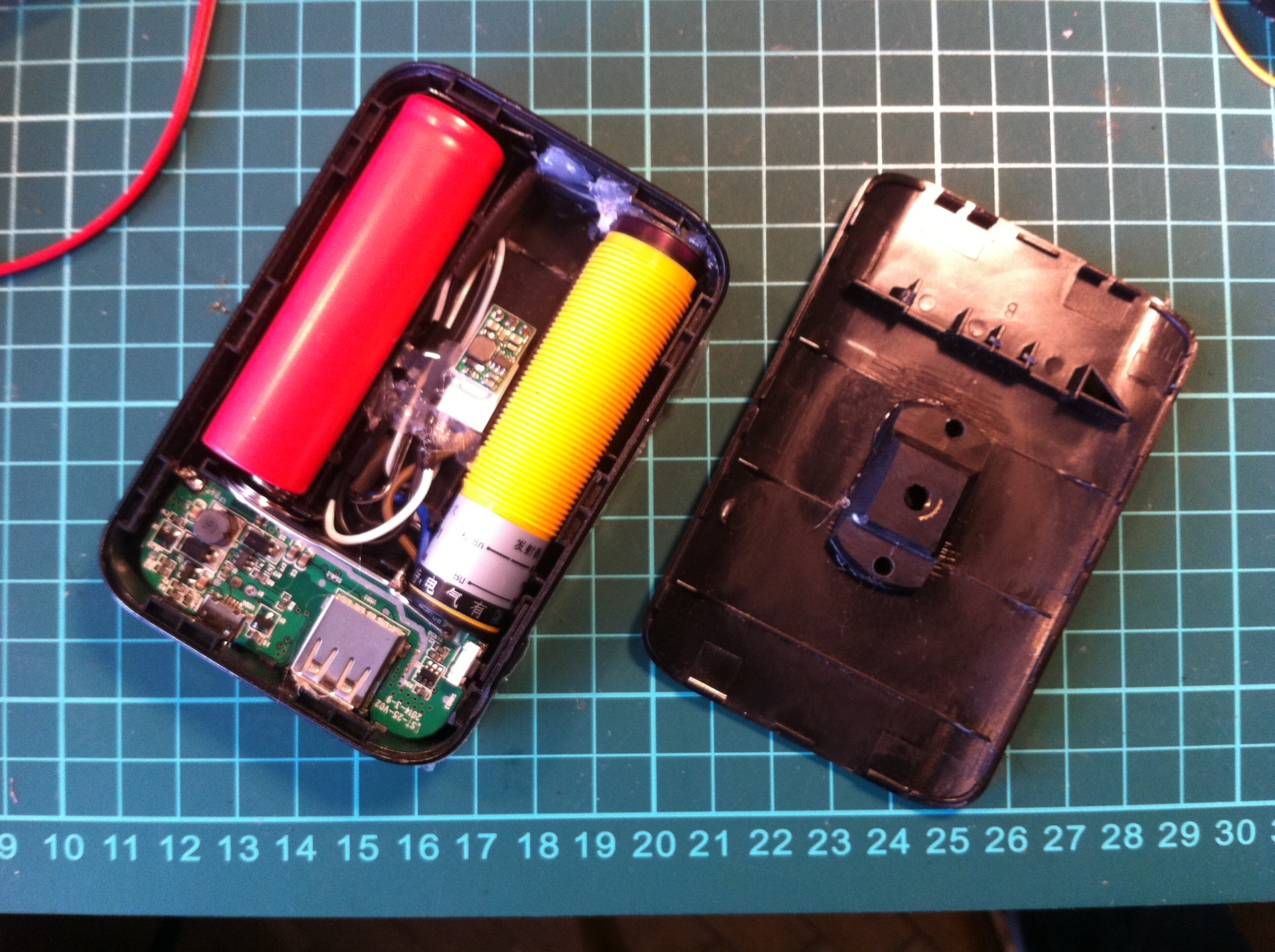
By a surprising coincidence, the size of the emitter coincided with the size of a standard 18650 battery. The solution came out on its own - take the case of autonomous charging! I drilled a hole under the sensor beam in the end, added a mount on the photo pole for GoPro with a sawn top, a battery and a miniature boost DC-DC converter up to 12V. The bonus is a bright green LED that illuminates a piece of silicone hose framing a hole for the beam, glowing when it is on.
The disadvantages of the design are the mass, even if one does not take into account the sequential double voltage boost of the DC-DC converters — built-in up to 5V and soldered to 12V. First, it is an active device, unstable to moisture and requiring charging. Secondly, it turned out that the load from the radiator power supply is not enough, and after a minute the power-bank electronics is turned off.
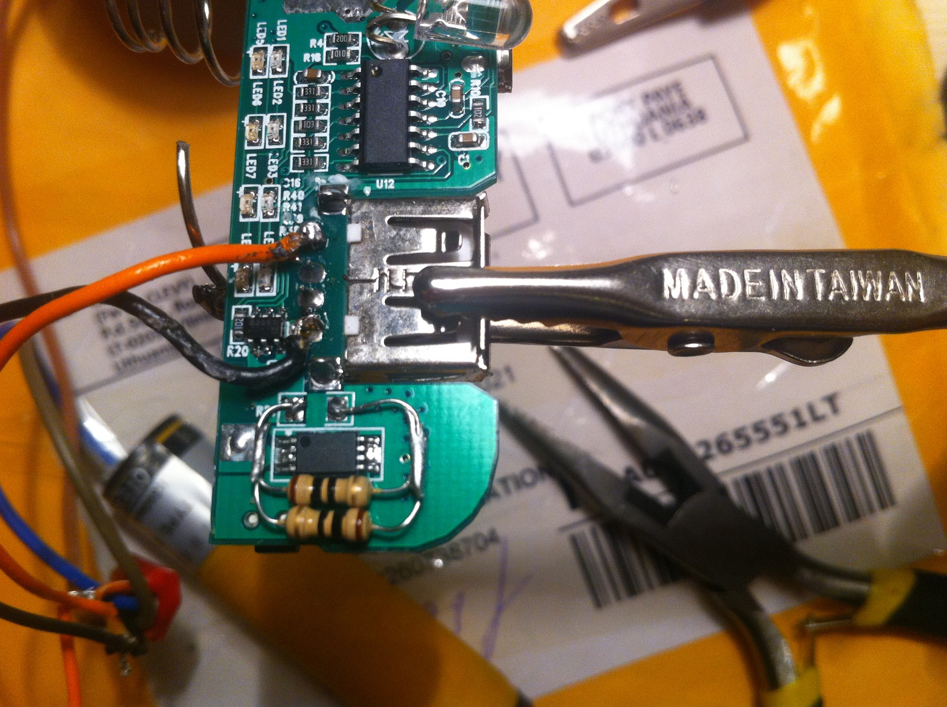
After long trials and noting out some very hard options, I found a way out - find and replace the shunt resistor for current measurement, so that the board would consider that the connected device was not yet charged. Intuition suggested that this resistor should be the largest on the board:
It doesn’t matter what the smd-resistance was then carefully soldered in: the following electrical circuits and logic of operation turned out to be greatly changed in the following purchased cases: they became unsuitable for my purposes: the power continued to turn on with the button, and it turned off only by reducing the current consumption of the connected device which is only suitable for charging phones.
Nevertheless, there are several power-banks with the correct logic at hand - there is enough to create a working prototype. Non-optimal energy consumption is also uncritical - the battery lasted for two days of continuous operation.
Knowing about the unreliable suppliers that change the scheme, the conclusion made - the more accessible and more common component, the better. It means that the receivers will be in other buildings (initially the idea was to do everything inside the power-banks, and transmit data via radio to the controller with a display).
Aluminum square profile, phone connector 6P4C, tripod mount for GoPro, rivets and lots of hot melt glue:
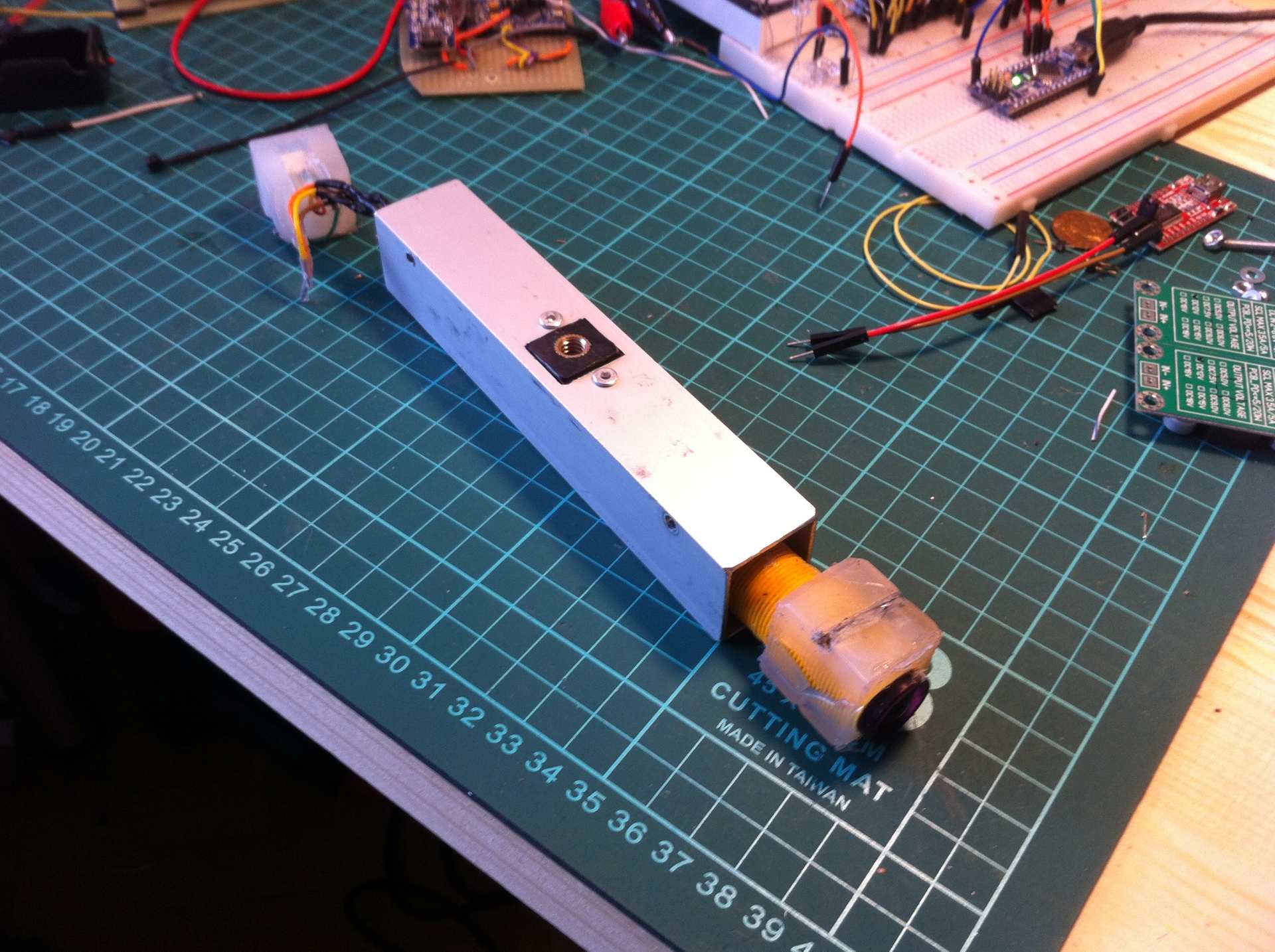
For molding hot melt cubes with components inside, I used a mandrel from a profile trimmed with silicone spray - after hardening, the workpiece is squeezed out with light pressure.
In addition, for convenience of setting, two flashing LEDs fused into the cubes are connected to the sensor output: so when aiming the sensors, you can immediately see the status, despite the controller display.
Mission accomplished - almost all components can be bought at the nearest hardware store! As a result, the starting gate with the installed sensors on the simplest photo pegs looks like this:
The controller is very simple - when the signal from the first sensor is received, the timer starts, from the second one it stops. The time is displayed on the OLED-display and sent over the air using the module nRF24L01. The circuit is also primitive - the display is connected with two wires on I2C, nRF24L01 - four wires via SPI, plus ground and power. Signal wires from two sensors - through voltage dividers to two inputs with support for hardware interrupts.
The first races are already on the way - with the prototype you need to hurry. The case took the power bank which came to hand (this time with the hardware power button) on four banks. The place of one battery will be taken by the display from the front side, and the telephone jacks from the reverse:
Place a second battery - soldered on an Arduino Pro Mini PCB made by LUT, a radio module, and a handful of resistors. There is a shortage of free space - henceforth it is worth considering that the wires occupy the most space:
No matter how scary it looks, the design turned out to be quite working, and after half a year the power of the power bank itself failed.
For easy debugging and firmware upgrades, I brought out the port of the USB serial adapter FT232RL, and connected it to the serial port of the Arduino Pro Mini. In order to charge the batteries through the same connector at the same time, I applied a small trick: you need to power the FTDI module through the VCC output from the internal circuit of the device, and the + 5V leg from the MiniUSB to redirect to the input for charging the power bank. To do this, it is enough to drop out zero resistance on the adapter, and make a power drain from the top pads:
The obvious way is to connect only GND, RX and TX does not work: the module will receive power through the RX-pin.
Trial rides on the street are held, time is considered, the sensors consistently register the crossing - hurray! And then - the competition on the nose, in just two weeks. So time is running out: you need to assemble a second set of sensors on the already proven design, and the second controller.
And that's why I love Arduino - for a quick start and work with a huge amount of iron without reading datasheets.
The second case and elegant, but expensive OLED-display plus batteries, mail does not have time to bring. I took what was at hand: a box for trifles, a telephone jack, four resistors, Arduino Nano, nRF24L01, some kind of display, a stabilizer KR142EN5A (there is always 12V power supply on the track). There are literally three soldering points, everything else is on the model wires, and after an hour the second set is ready!
On the change - the judicial panel! Box for radio equipment, Arduino Uno, nRF24L01 and a pair of displays with eight seven-segment indicators. I connected everything again with the model wires. In the case I drilled a hole for the USB port for powering from an external power-bank or laptop, displays - hot-melt attached to the transparent cover. Taking a package through the radio module and bringing it to one of the two displays is not a very difficult task, the code was written quickly. The result is a referee's console, duplicating information from the controllers, and a second telemetry set:
Before the competition, I checked all the devices again, and for good reason: in one of the controllers, the quartz was on standard 16 MHz, and in the second - 16.384 MHz! Needless to say, they considered time as differently.
He charged the batteries and checked the connection - the radio modules showed themselves excellently by transmitting data to tens of meters with the antenna divorced on the printed circuit board. All devices together look more impressive:
For good luck, the day of races turned out to be warm and dry - the equipment will survive. While the track is being laid out - I place the equipment:

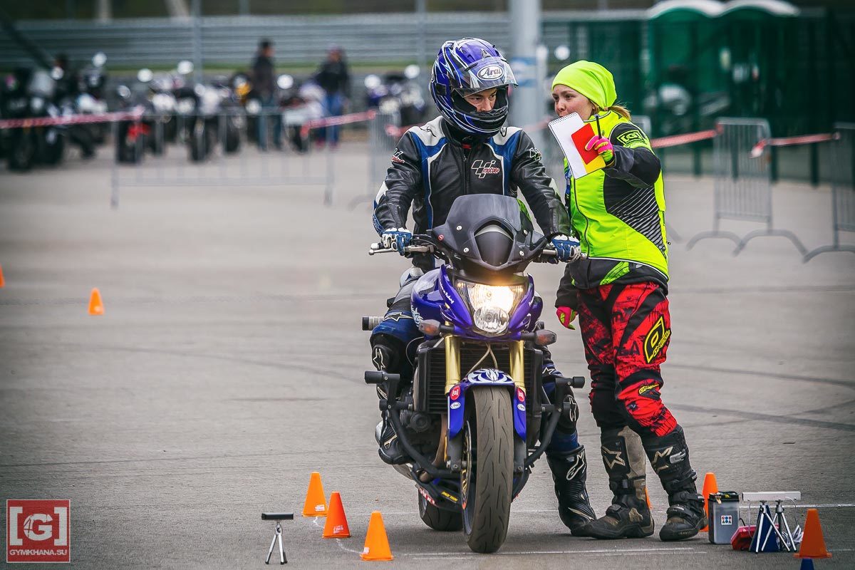
Begin the first races and - cheers, everything works clearly! No false positives, the time is cut off accurately. The girls at the start help the athletes to place the bike at the starting gates and fix the result at the finish. The portable referee console helps pretty - when in the sunlight, the LED indicators of the controller lying on the pavement are almost invisible.
The venture paid off: almost a hundred parallel races (and these are two hundred fixed times), there are no failures, and the difference between the first two places in the class of road motorcycles is 0.1 seconds, which is not easy to measure manually. So it is decided: the project - to be!
Looking ahead - everything turned out, the devices successfully worked on all three stages of the moto-jihhane [G] -RSBK championship, and are actively used during training. Collected in the end were:
- Check in controller
- sensors for the controller
- scoreboard
- referee panel
as well as something else!
The sensors were bought and after half an hour the prototype flashed on the display. True, I was slightly mistaken in the belief that everything else would be enough for me for several evenings.
The article does not have schemes in Fritzing - manuals on connecting sensors and displays on the network is complete, and there are no source codes -
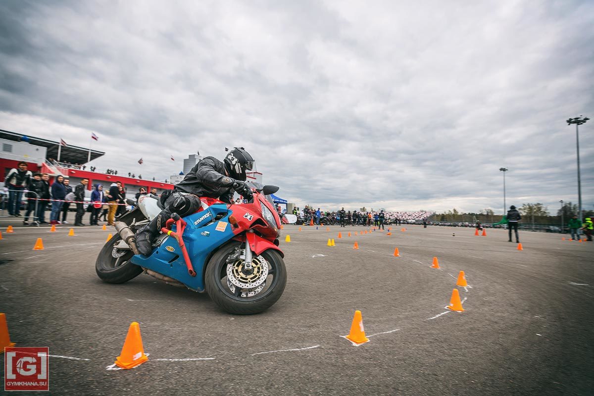
Motodzhimkhana - a sport that consists in high-speed maneuvering on a motorcycle on the highway, marked by artificial obstacles. Precise taxiing and braking, angles of inclination with sparking steps on the asphalt, and moderate speeds make jimkhan both fascinating and fairly safe. In addition, competitions are held on motorcycles suitable for driving on public roads, i.e. no need to go on the track with a specially prepared bike in the trailer - the bike that you have is suitable.
At competitions, the race starts from the starting box, which is bounded by cones, and then the drive along the track follows, and the finish line is also to the cones-limited box, located next to the start. Sensors need two - the intersection of the start and the intersection of the finish. So far, it has been decided to note the time directly from the participant’s departure from the box, later on by a traffic light signal, and the sensor can be used to check the false start.
Yes, entertainment adds pair runs on two identical tracks, which means that there should be two sets of equipment.
Sensors
After examining the range, I found and bought barrier optical beam crossing sensors, consisting of two modules - a radiator and a receiver. A wide range of supply voltage - 6-36V, the signal from the sensor - NPN-output. During tests in the room, they proved to be excellent - a range of several meters, good focusing of the beam, speed of response - within milliseconds.
It is good, now you need to decide how to feed, strengthen and guide them. All IT-shniki know that standards are good, therefore I will feed from 12V, and to fix and guide them - with standard photo supports.
Emitters
By a surprising coincidence, the size of the emitter coincided with the size of a standard 18650 battery. The solution came out on its own - take the case of autonomous charging! I drilled a hole under the sensor beam in the end, added a mount on the photo pole for GoPro with a sawn top, a battery and a miniature boost DC-DC converter up to 12V. The bonus is a bright green LED that illuminates a piece of silicone hose framing a hole for the beam, glowing when it is on.
The disadvantages of the design are the mass, even if one does not take into account the sequential double voltage boost of the DC-DC converters — built-in up to 5V and soldered to 12V. First, it is an active device, unstable to moisture and requiring charging. Secondly, it turned out that the load from the radiator power supply is not enough, and after a minute the power-bank electronics is turned off.
After long trials and noting out some very hard options, I found a way out - find and replace the shunt resistor for current measurement, so that the board would consider that the connected device was not yet charged. Intuition suggested that this resistor should be the largest on the board:
It doesn’t matter what the smd-resistance was then carefully soldered in: the following electrical circuits and logic of operation turned out to be greatly changed in the following purchased cases: they became unsuitable for my purposes: the power continued to turn on with the button, and it turned off only by reducing the current consumption of the connected device which is only suitable for charging phones.
Nevertheless, there are several power-banks with the correct logic at hand - there is enough to create a working prototype. Non-optimal energy consumption is also uncritical - the battery lasted for two days of continuous operation.
Receivers
Knowing about the unreliable suppliers that change the scheme, the conclusion made - the more accessible and more common component, the better. It means that the receivers will be in other buildings (initially the idea was to do everything inside the power-banks, and transmit data via radio to the controller with a display).
Aluminum square profile, phone connector 6P4C, tripod mount for GoPro, rivets and lots of hot melt glue:
For molding hot melt cubes with components inside, I used a mandrel from a profile trimmed with silicone spray - after hardening, the workpiece is squeezed out with light pressure.
In addition, for convenience of setting, two flashing LEDs fused into the cubes are connected to the sensor output: so when aiming the sensors, you can immediately see the status, despite the controller display.
Mission accomplished - almost all components can be bought at the nearest hardware store! As a result, the starting gate with the installed sensors on the simplest photo pegs looks like this:
Controller
The controller is very simple - when the signal from the first sensor is received, the timer starts, from the second one it stops. The time is displayed on the OLED-display and sent over the air using the module nRF24L01. The circuit is also primitive - the display is connected with two wires on I2C, nRF24L01 - four wires via SPI, plus ground and power. Signal wires from two sensors - through voltage dividers to two inputs with support for hardware interrupts.
The first races are already on the way - with the prototype you need to hurry. The case took the power bank which came to hand (this time with the hardware power button) on four banks. The place of one battery will be taken by the display from the front side, and the telephone jacks from the reverse:
Place a second battery - soldered on an Arduino Pro Mini PCB made by LUT, a radio module, and a handful of resistors. There is a shortage of free space - henceforth it is worth considering that the wires occupy the most space:
No matter how scary it looks, the design turned out to be quite working, and after half a year the power of the power bank itself failed.
For easy debugging and firmware upgrades, I brought out the port of the USB serial adapter FT232RL, and connected it to the serial port of the Arduino Pro Mini. In order to charge the batteries through the same connector at the same time, I applied a small trick: you need to power the FTDI module through the VCC output from the internal circuit of the device, and the + 5V leg from the MiniUSB to redirect to the input for charging the power bank. To do this, it is enough to drop out zero resistance on the adapter, and make a power drain from the top pads:
The obvious way is to connect only GND, RX and TX does not work: the module will receive power through the RX-pin.
Second controller
Trial rides on the street are held, time is considered, the sensors consistently register the crossing - hurray! And then - the competition on the nose, in just two weeks. So time is running out: you need to assemble a second set of sensors on the already proven design, and the second controller.
And that's why I love Arduino - for a quick start and work with a huge amount of iron without reading datasheets.
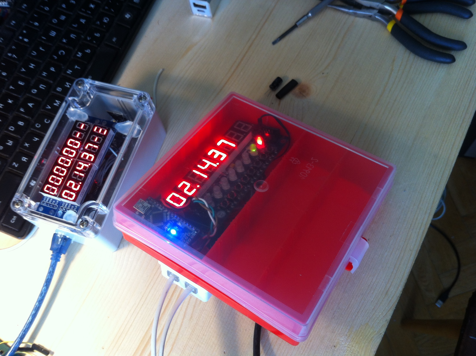
The second case and elegant, but expensive OLED-display plus batteries, mail does not have time to bring. I took what was at hand: a box for trifles, a telephone jack, four resistors, Arduino Nano, nRF24L01, some kind of display, a stabilizer KR142EN5A (there is always 12V power supply on the track). There are literally three soldering points, everything else is on the model wires, and after an hour the second set is ready!
On the change - the judicial panel! Box for radio equipment, Arduino Uno, nRF24L01 and a pair of displays with eight seven-segment indicators. I connected everything again with the model wires. In the case I drilled a hole for the USB port for powering from an external power-bank or laptop, displays - hot-melt attached to the transparent cover. Taking a package through the radio module and bringing it to one of the two displays is not a very difficult task, the code was written quickly. The result is a referee's console, duplicating information from the controllers, and a second telemetry set:
Competition
Before the competition, I checked all the devices again, and for good reason: in one of the controllers, the quartz was on standard 16 MHz, and in the second - 16.384 MHz! Needless to say, they considered time as differently.
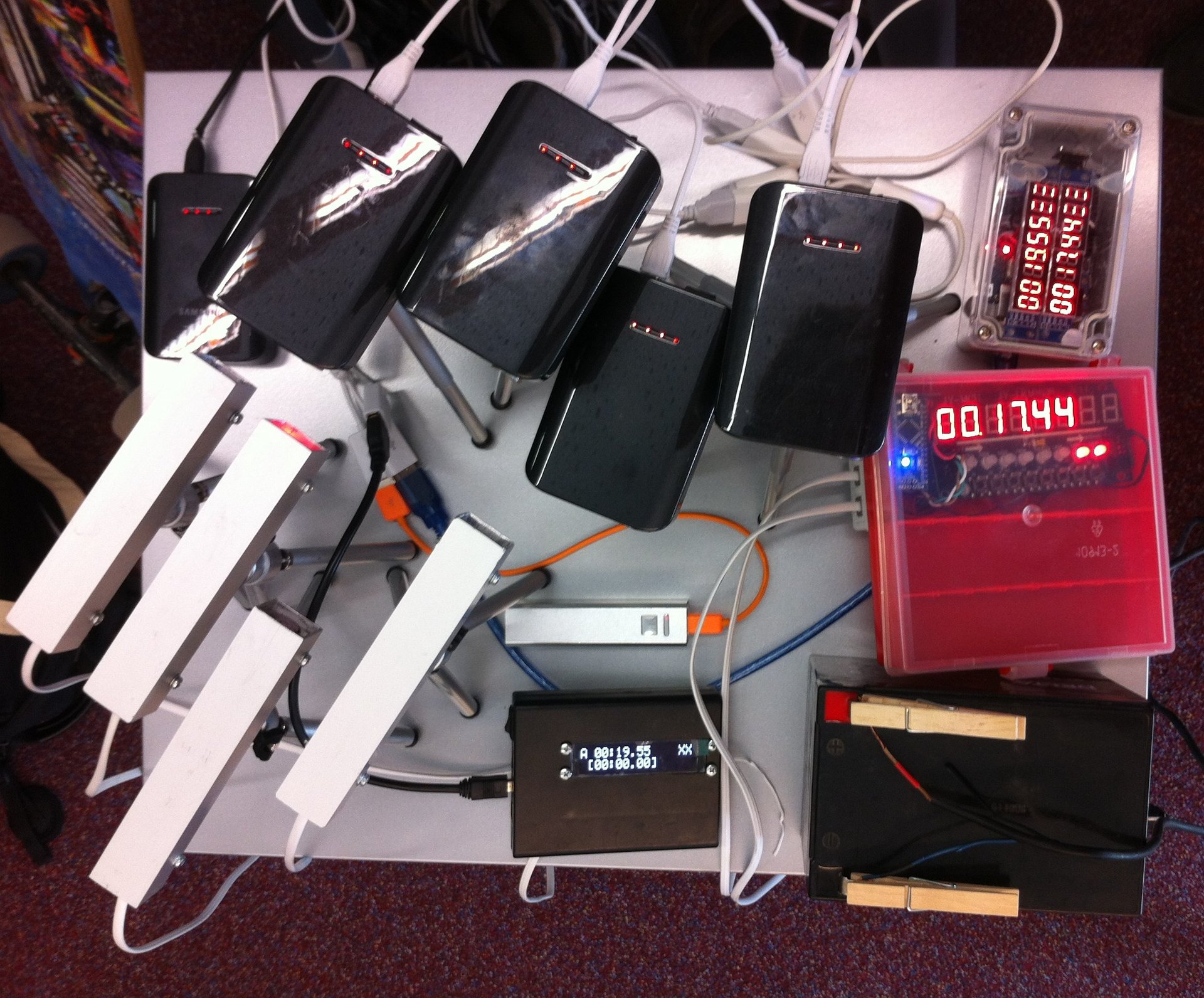
He charged the batteries and checked the connection - the radio modules showed themselves excellently by transmitting data to tens of meters with the antenna divorced on the printed circuit board. All devices together look more impressive:
For good luck, the day of races turned out to be warm and dry - the equipment will survive. While the track is being laid out - I place the equipment:
Begin the first races and - cheers, everything works clearly! No false positives, the time is cut off accurately. The girls at the start help the athletes to place the bike at the starting gates and fix the result at the finish. The portable referee console helps pretty - when in the sunlight, the LED indicators of the controller lying on the pavement are almost invisible.
The venture paid off: almost a hundred parallel races (and these are two hundred fixed times), there are no failures, and the difference between the first two places in the class of road motorcycles is 0.1 seconds, which is not easy to measure manually. So it is decided: the project - to be!