Model-oriented design. Brushless DC Motor

A general answer to this question is still being prepared, but I can give you a real and fresh example about a particular one right now. It turned out in my hands here, as always by accident, the text from the leading specialist in our country on electric drive Kalachev Yuri Nikolaevich, author of the book Modeling in an electric drive. Instructions for understanding. along with his kind permission to publish. This text is still being prepared for publication in specialized publications, but readers of the Habrir will see it first.
Further, under the cut,
Kalachev Yu. N., Lantsev V.Yu., Okulov EV
Electric drive with a brushless DC motor
(the practice of applying simulation and code generation at Aeroelectromash JSC)
Cheers, comrades !!! It happened !!!
Finally, we saw the fruits of progressive trends grown in the domestic drive industry.
The article discusses the technology of designing an electric drive using simulation and code generation. (Correct model-oriented design )
As for modeling, this is not a new issue for our drivers. But few people have tried automatic code generation of the drive controller program from its model, and on a global scale. ...
We dare to assert that this useful trend (automatic writing of a program by another program) will actively develop in the future digital world .... The one who starts earlier will win.
We want to make a reservation that code generation, in our opinion, does not cancel and does not replace the programmer, but only helps him. In this case, of course, we believe that the SI code of the generated program should be open for it.
So we do, the result of automatic code generation is C code, open for viewing and analysis.
In our case, the control object was a certain electric drive with a brushless DC motor (BDT), the shaft of which is connected to a gearbox that turns rotation into translational motion of the rod.
The task of the electric drive is quite standard - to position the shaft of the rod, preferably faster and more precisely ... Often these drives are used to control the rudders of unmanned aerial vehicles.
The device control unit was designed and manufactured in the electric drive department of Aeroelectromash JSC on the basis of the 1986ВЭ1Т microcontroller (PKK Milander JSC). It was necessary to create algorithms and a controller control program for the purpose of its further use in practical problems.
The work was carried out jointly by specialists of the 3V-service company and employees of the electric drive department of Aeroelectromash JSC.
The first task that our team faced was the identification of the control object. For this, some measurements of engine characteristics were carried out, which turned out to be quite specific.
For example, the measured motor EMF had a very bizarre shape, shown in Figure 1.
Figure 1. Measured motor EMF.
If the reader is familiar with the Simulink program, then he knows that there, in the model of the motor with constants and magnets, there is a choice of a sinusoidal or trapezoidal EMF.
Well, and where to go to the poor peasant? Where is the sine here, and where is the trapezoid? (The right modeling tools must be open!). In the SimInTech environment, even such engine imperfections can be taken into account. We have set the EMF form shown in Fig. 2

Figure 2. Engine EMF created in SimInTech
Find the two differences in Fig. 1 and Fig. 2. We found one thing - color.
The next feature of the engine turned out to be its significant tooth moment, due to the geometry of the stator magnetic circuit and the absence of beveling of the grooves of the rotor magnets. The moment was measured experimentally and introduced into the model. The graph of the tooth moment is shown in Fig. 3. 
Figure 3. Prong moment.
In addition, the magnetization losses were taken into account in the engine model, which is absent in mathematical models from other developers of simulation programs.
Further, the operation of the electric drive was compared with the simulation results in test modes. Below in Fig. Figures 4 and 5 show the results of an idle test (maximum frequency without load). 
Figure 4. Idling. Real engine.

Figure 5. Phase current idle. Simulation result.
Conclusion:
Oscillograms of real and model idling coincide. Visually, the difference is not visible.
After a successful idle test, a dynamic impact test was performed on an engine with a gearbox attached. In this experiment, a constant voltage was applied to the motor windings with a reverse at a frequency of 30 Hz. In this case, the output link oscillated with the same frequency. 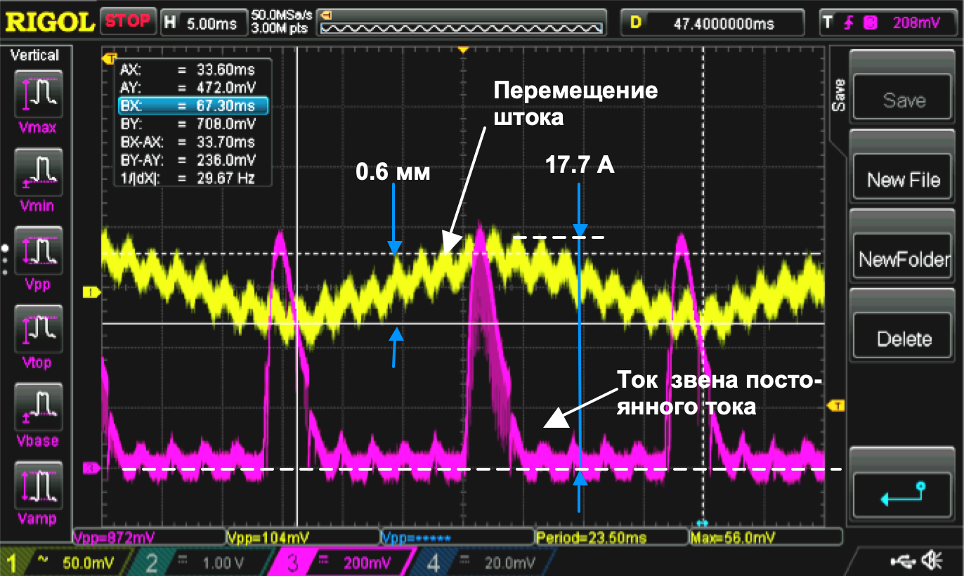
Figure 6 shows the results of this experiment: Figure 6. Real engine under load
(The signals were shot with interference. High-frequency jitter and blur are interference in the signals of the position and current sensors).
The data obtained were compared with a drive model operating in a similar mode (Fig. 7).

Figure 7. Model under load
Conclusions:
- The movements of the rod in reality and on the model completely coincide
- Peak values of the real motor current and the model coincide with an accuracy of the measurement error.
The type of the verified model of the power and mechanical parts of the electric drive built on standard library elements of the SimInTech program is shown in Fig. 8.
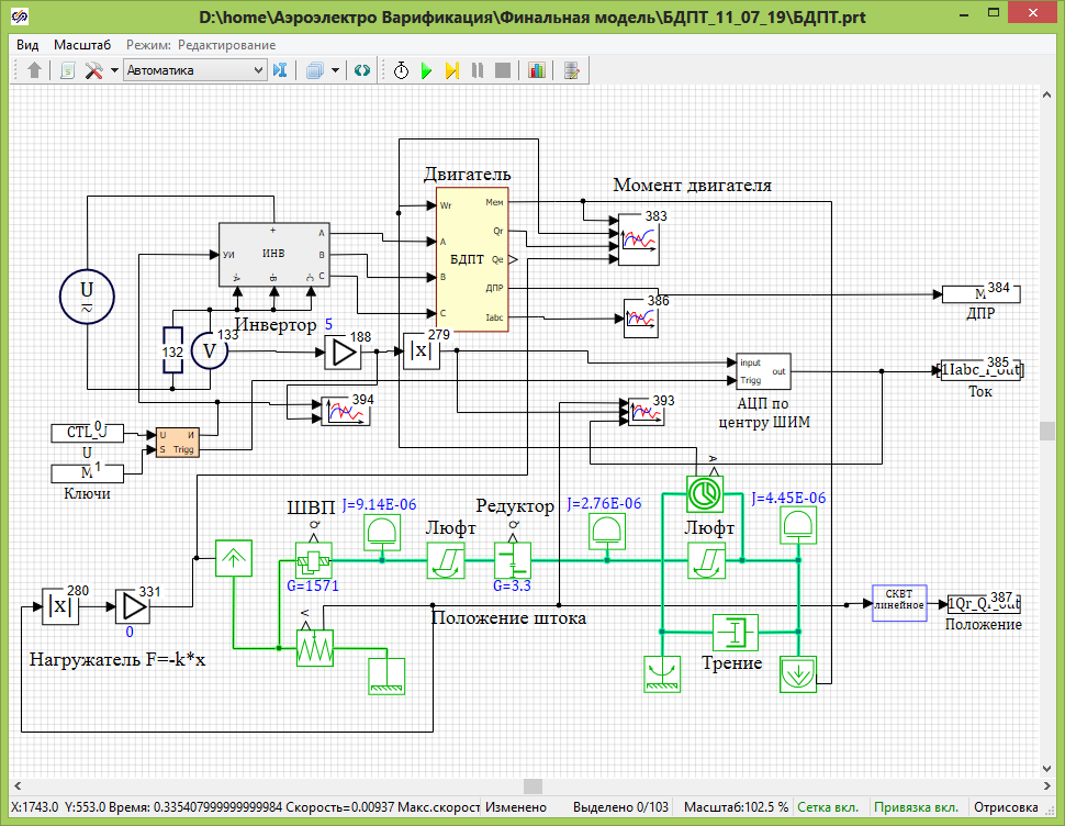
Figure 8. Scheme of a complex model of an electric drive, including the mechanical part.
It consists of models:
- power inverter
- motor with rotor position sensor (DPR)
- mechanical transmission
- current sensor
- loader
After making sure that the model’s behavior matches the behavior of a real product, according to the simulation results, you can select the necessary structure of the control system (CS) and configure it for the different input types listed in the technical task.
In our case, good results were shown by a dual-circuit position control system with damping coupling in speed. A model view of this structure is shown in Fig. 9.
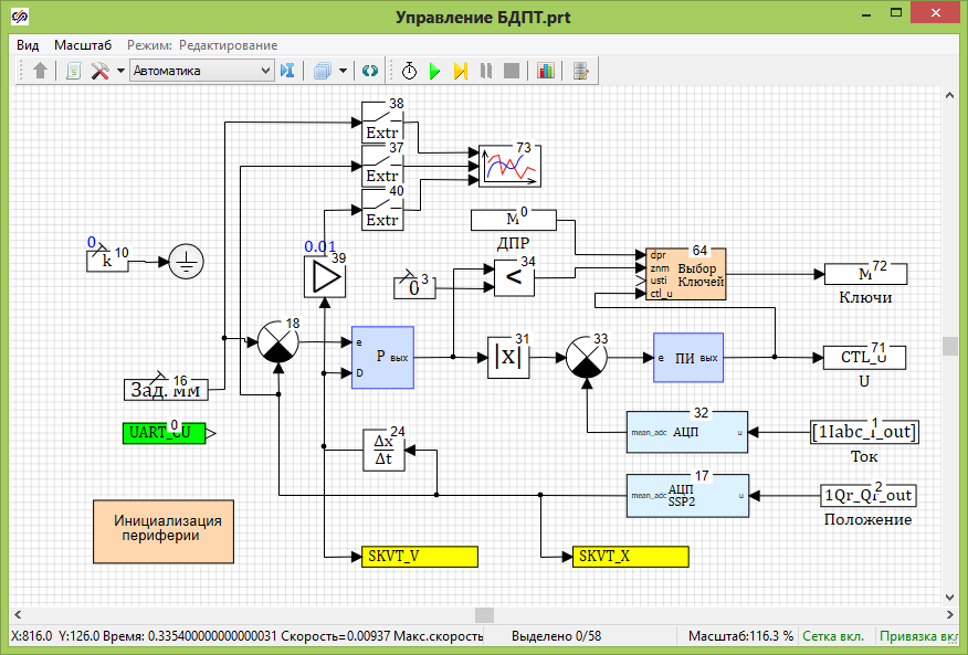
Figure 9. The design scheme of the drive control program.
With further use of code generation, there is no need for manual coding of control system algorithms - a finished project in the development environment of Keil uVision is created automatically. After assembling the binary image of the program, it can be translated into our processor (1986BE1T).
Note that the “Key Choice”, “Peripheral Initialization”, “ADC”, “SSP2 ADC” model blocks in the simulation mode implement the corresponding mathematical models, and during code generation, they are replaced with libraries for working with the peripherals of the processor used.
After choosing the structure of the control system and its settings, we had to:
- carry out automatic code generation of the program
- write the received program to the controller
- capture great results
According to Fig. 10, you can compare the operation of the model and the real drive. As a position reference, a sinusoid with a frequency of 3 Hz and an amplitude of 3 mm was used.
To obtain data from the controller, a special part was provided in its program that provided the reading of internal signals via a serial interface. The user, while the drive is running, sees the results of the firmware in the SimInTech window.

Figure 10. Comparison of the model and the real drive.
Well, even the color is the same here ....
Hurray, comrades !!! It happened !!!
Everyone who is interested in the topic of the electric drive recommend downloading the free book Kalachev Yu.N. Modeling in the electric drive.