Texturing, or what you need to know to become a Surface Artist. Part 4. Models, normals, and sweep
- Tutorial
Models, Normals, and Sweep
In my humble opinion, a texture artist should be responsible for the unfolding. Not for the scan itself (it should be done by 3D artists or even individual UV specialists in general), but its styling. It should determine how the islands should be located, how they should be turned, and how much they can be pulled in a given situation depending on the requirements.
It is the artist by texture (and later, by surface) that must determine the scale (scale) of the islands (more on that later).
In this part, we look at models, sweeps, and normals. Create textures for the first full-fledged model (albeit a simple one) and configure it in Unreal Engine 4.
Attention. It is assumed that at this point you figured out the normal map, and why you need it. Because in this tutorial we will talk about it very often.
Part 1. Pixel here .
Part 2. Masks and textures here .
Part 3. PBR and Materials here .
Part 4. Models, normals and scan - you read it.
Part 5. Material system here .
Models and PBR. Practice
I will not talk about how to create models or how to clean / build a grid. This information can be obtained from many courses, which are both in the public domain and in the paid. Our task now is to analyze the specific limitations in the structures of models for games and what solutions exist at the moment.
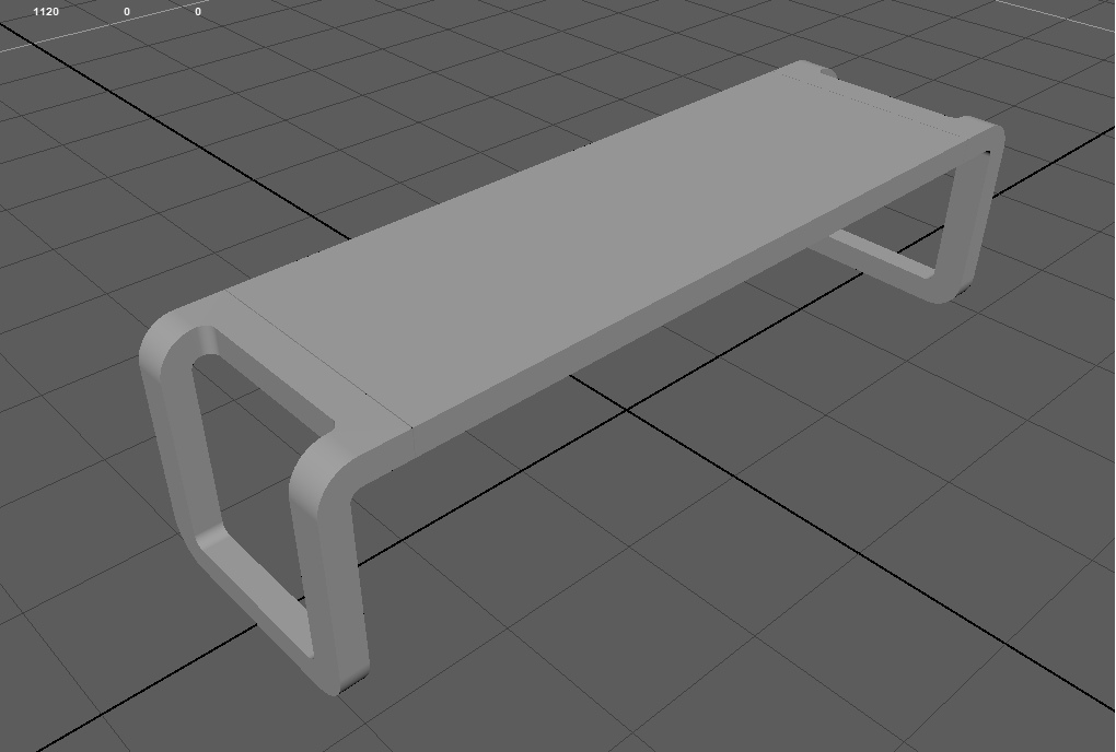
But first, we will texture the model, and for one look at it the first limitation. We will work on this shop:
For this, we will need to download the mesh itself and a pre-prepared normal map for it (below I will explain clearly why we prepared it). Link here .
I would also like to make its base wooden, and its legs metal. Well, a little dirt spread. Accordingly, we need 2 materials:
- tree
- machined metal.
We will not take out the dirt in a separate material, but use the generator in Substance Painter and create dirt inside the program.
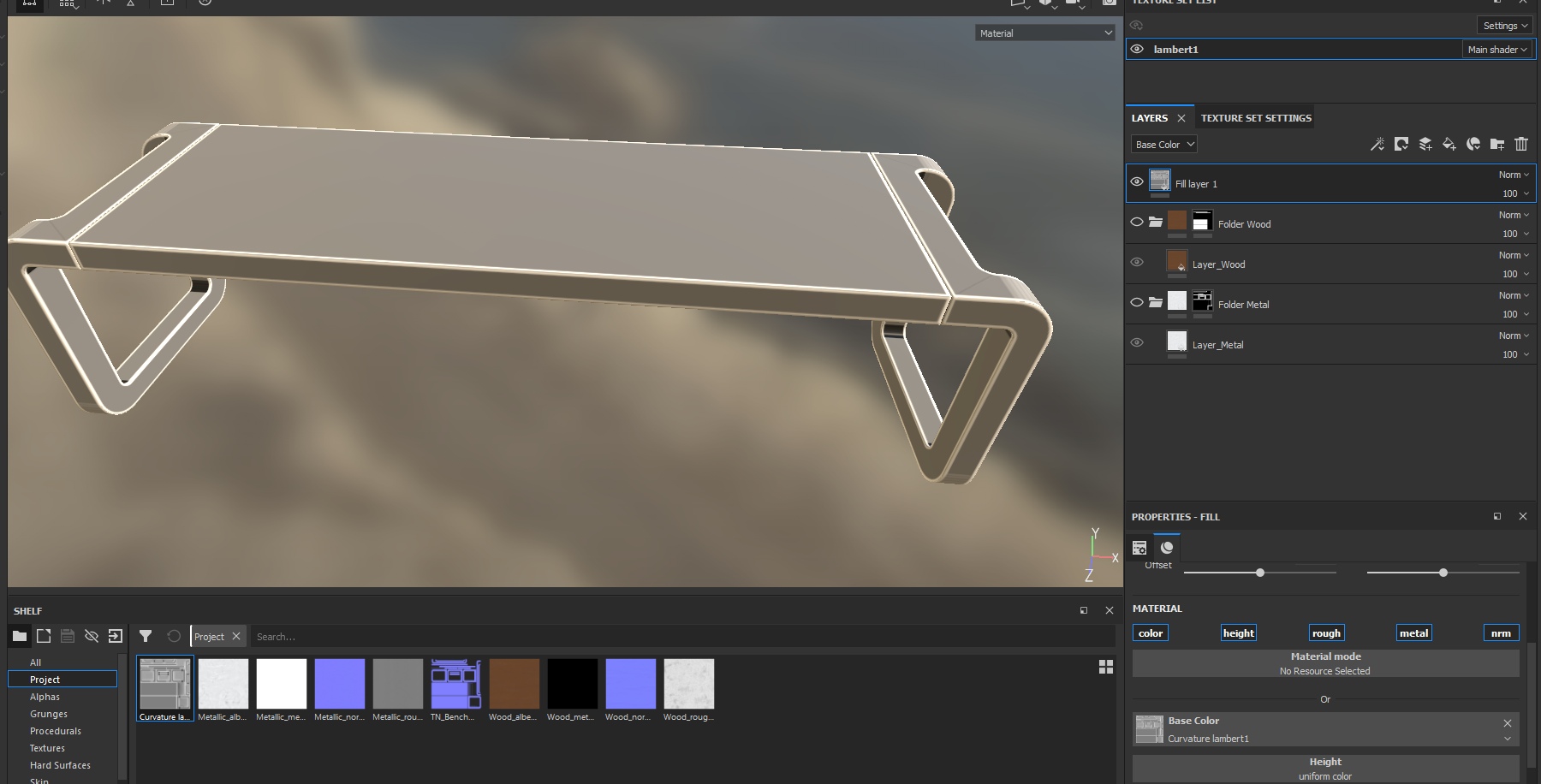
Let's start the practice and create a standard project, specify a bench, textures and run it:
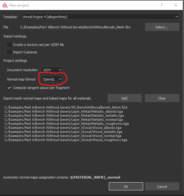
Please note that this time we will need to specify Normal Map Format - OpenGL. I already wrote in the last part that normal maps are read differently by different programs. And this card was generated for programs that use OpenGL.
We have loaded 9 textures + main mesh.
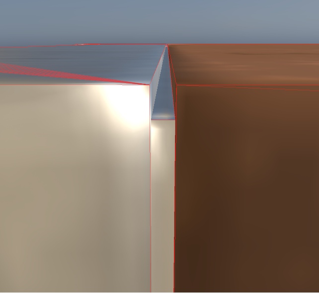
Now we will not make any layers and folders, but let's look at the shop as close as possible. We are especially interested in the edges of the object:
For example, I highlighted one side of the bench. Now she is as perfect as possible. That is, the two sides came together in one rib and created the perfect angle. No matter how much we bring this joint closer, it will always be perfectly even. In reality, there are no ideal angles, and even the razor’s edge will be rounded if properly enlarged. That is why the ribs do not look cinematic now. Such models look very weak, and when we see them in the game, we immediately feel all the weakness of the visual picture, even if we do not notice these angles directly on the models.
This is the first limitation of the model.
Previously, when the resources of video cards did not allow processing of millions of vertices in one frame, the solution was in the textures of normal cards. They indicated how light should begin to be reflected so that it feels as if these borders have a rounding. Specifically for this bench, such a normal map looks like this:
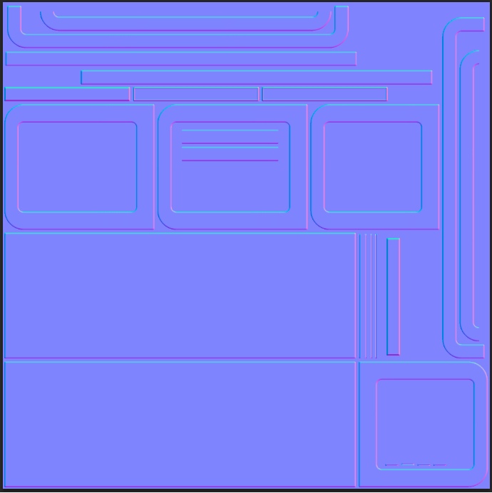
Even just looking at a set of parameters in the form of this map, you can feel how the normal map will smooth out the corners.
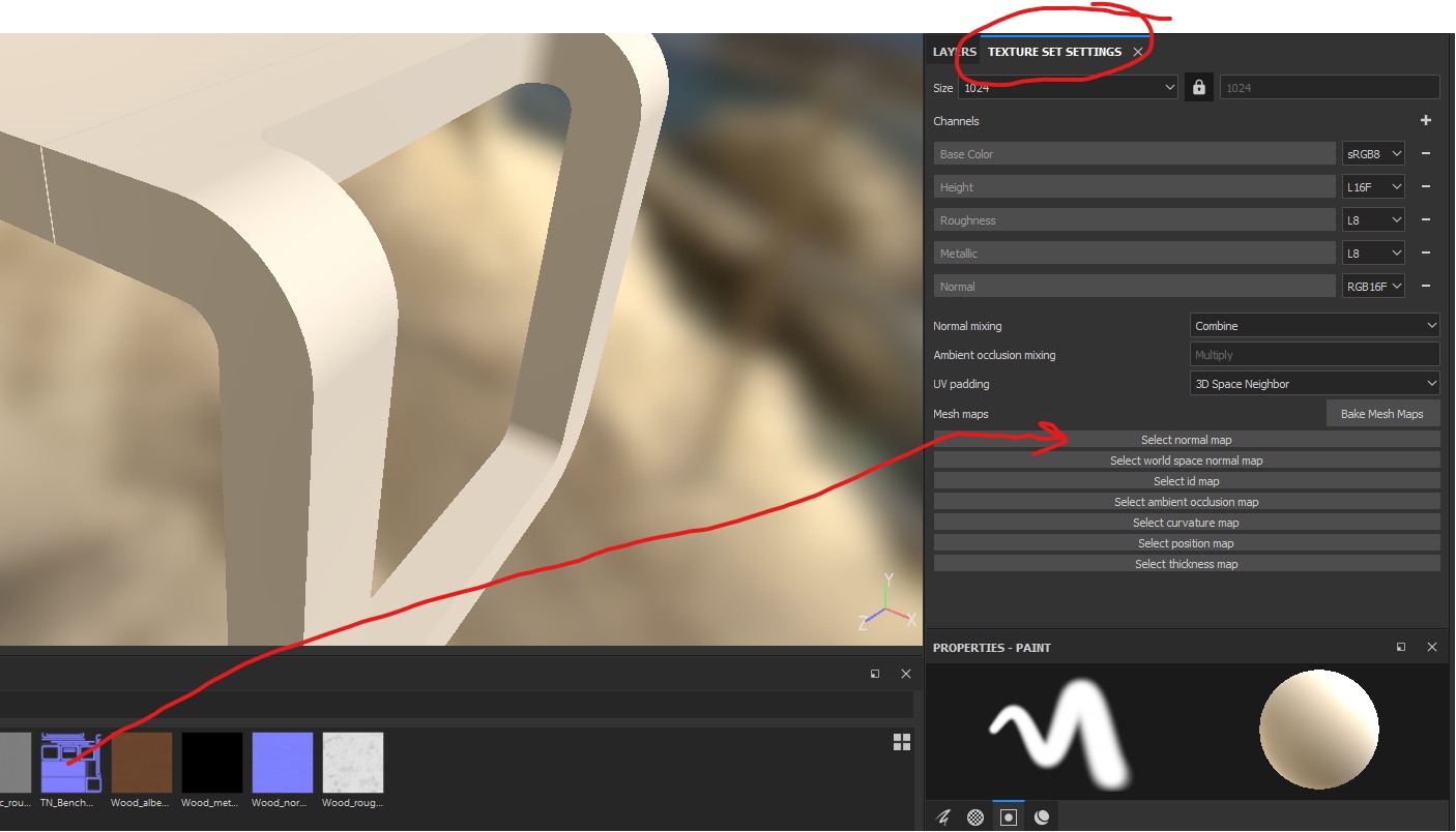
Now let's indicate this normal map as the main one (that is, it will always be attached to the result, like the lowest layer without a mask). To do this, we need to open the settings for the main textures of the object and specify our texture in the parameters of the normal maps:
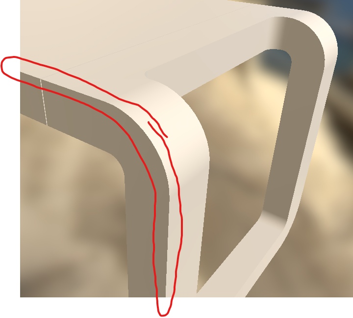
And look at the result:
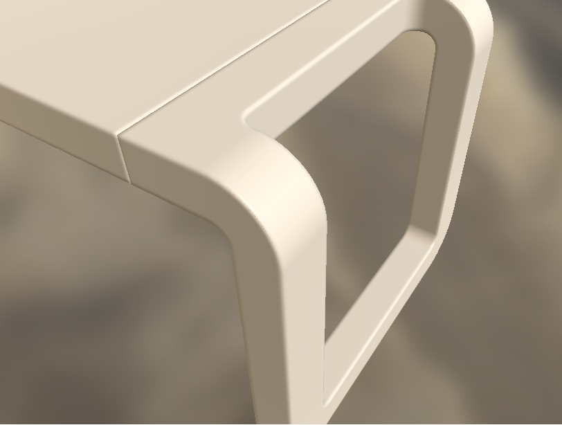
This is the first most famous and often used method of dealing with sharp edges - to bake chamfers in normal maps. That is, the model is still tough, but the normal map at its edges begins to distort the light, which creates the illusion of a beautiful soft bevel. On the Internet you can find a ton of information on how to do this. For simple objects like this bench, you can not make high-poly models (and not bake from it accordingly), but generate a normal map with chamfers in the programs. For example, the Modo program can do this . Our bench has a normal map generated in Modo.
But let’s omit the topic of chamfering and continue texturing the bench.
If the normals are concave
If your chamfers did not become as smooth as mine, but the illusion of troughs appeared, then when creating a project in Substance Painter you forgot to change the normal display format from DirectX to OpenGL.
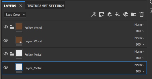
Now create 2 folders for the layers, create and transfer 1 layer to each and insert all texture maps into each layer. Do not forget about naming, so as not to get confused:
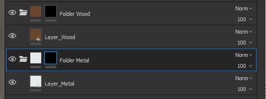
Now the layer hierarchy is not important to us, since these materials (metal and wood) will not intersect with each other - we will not have a situation where metal begins to appear through the tree and vice versa. But we still need masks, so now we need to limit the visibility of the layers on different islands, so now add black masks to both folders:
And now we indicate which scan islands should be white on the masks and which should be black. To do this, select the mask and switch to the island selection mode:
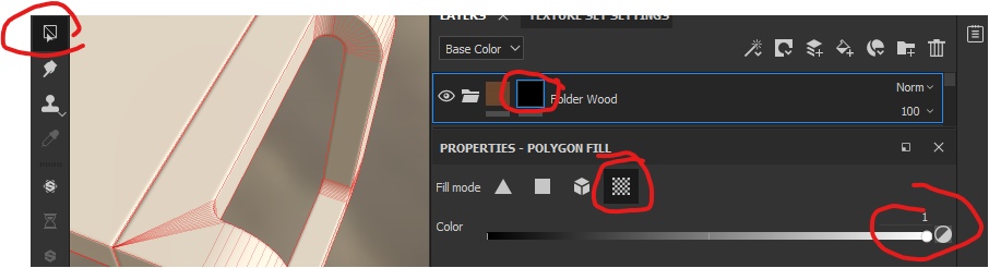
Click on the model on the main bench (if you selected the tree mask) and get the following result:
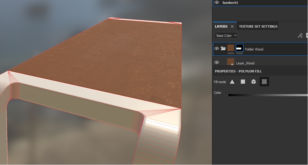
As you can see in the screenshot, the mask has been updated, and now it has a huge white strip, which is located on the island. In this way, we will paint the entire bench around:
The material of the tree itself was not the most successful, but our goal now is not to do everything as beautifully as possible, but to understand the principles of work.
Do the same with the mask for the metal, noting the visible area with islands of legs. Select the metal mask and indicate the necessary parts of the object:
You also need to get into hard-to-reach places at the joints and mark the islands we need for both wood and metal:
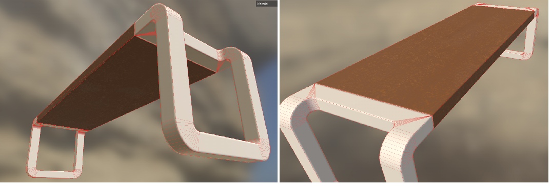
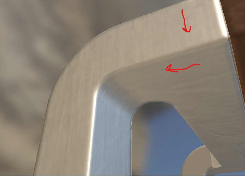
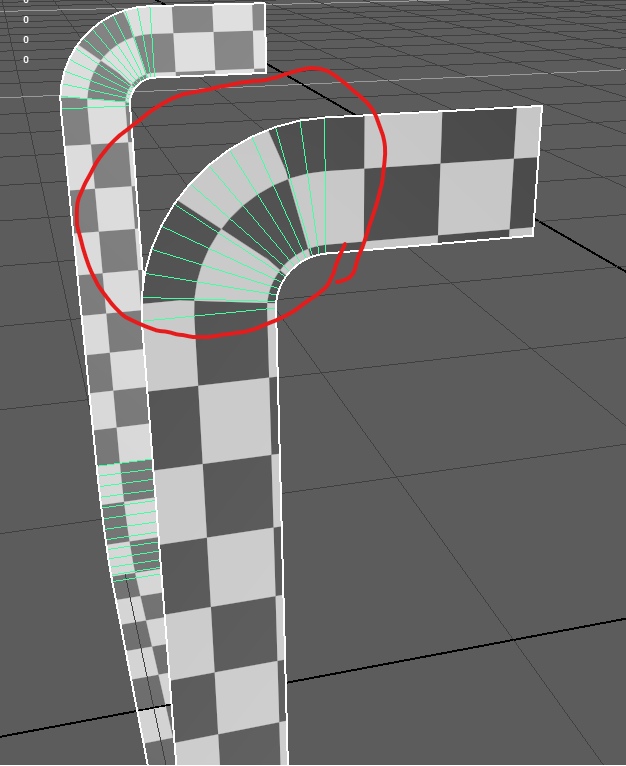
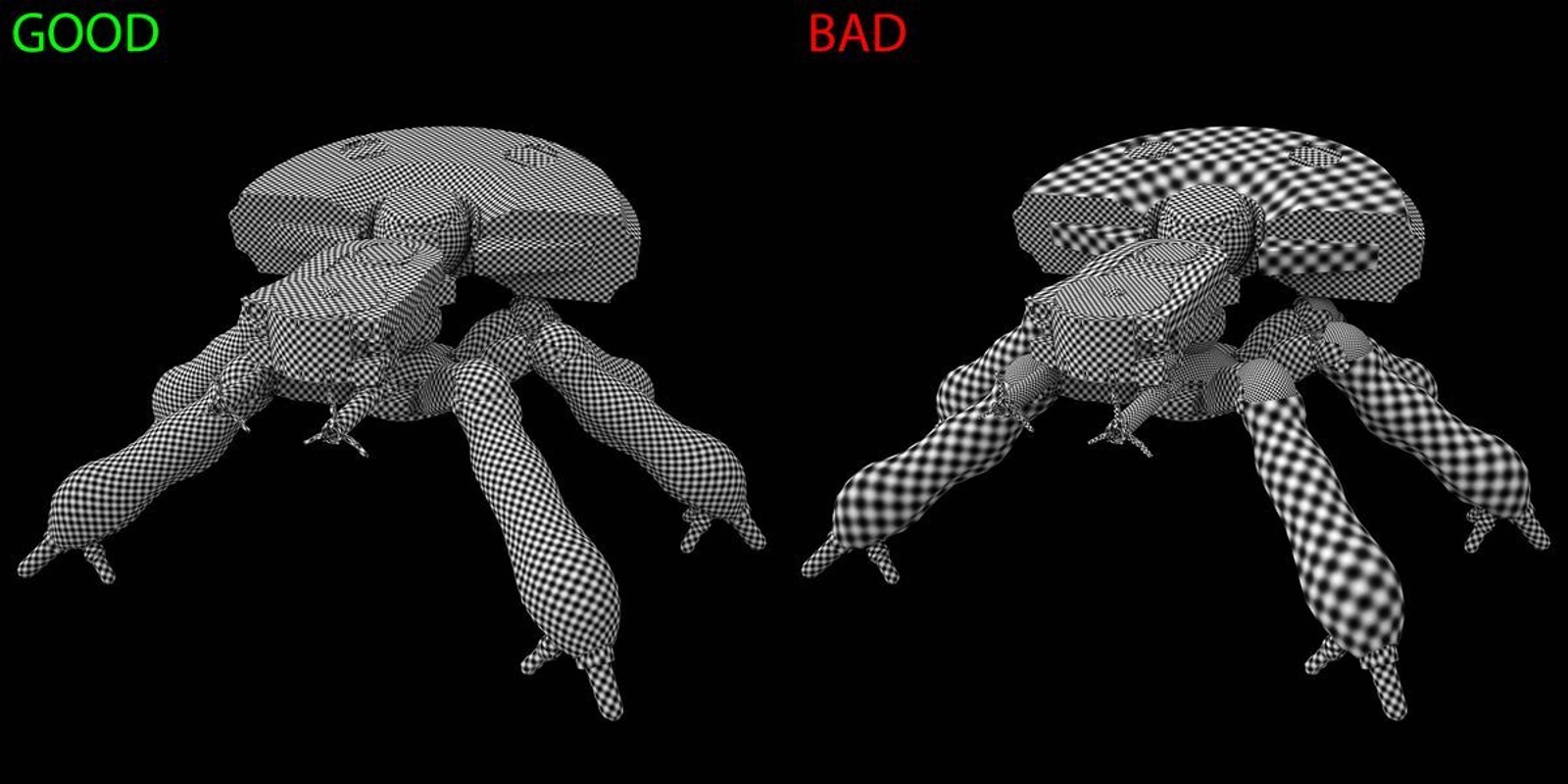
If you carefully examine the legs, you will notice the second limitation of the model .
The scan was not performed correctly, and the steel pattern between the sides of the legs is not consistent - its texture is directed in different directions, which is visually striking (the direction is marked by arrows):
This is a limitation that can be overcome by aligning the islands and stretching them. Now the island on which the down arrow is drawn looks like this (highlighted in orange):
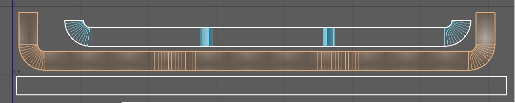
In order to fix the problem, it is necessary that the island be straightened in one line:
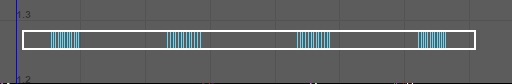
Then we will solve this restriction, but we will have another - pulls:
Draws are not scary if they are not very noticeable, or the texture on them does not issue them. But you need to be careful with them, and sometimes you have to put up with the fact that there may be inconsistencies in materials.
In general, the problem of seams in objects remains unsolved until the end. In the future, we will consider other options for how to get rid of seams and even try really cool methods in the next part.
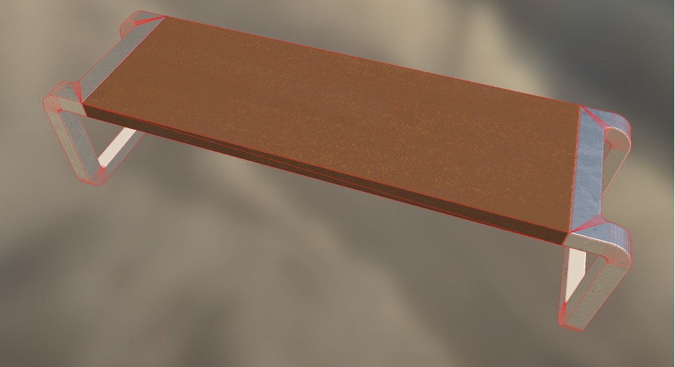
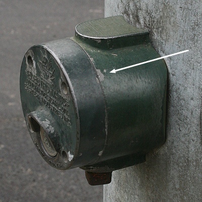
Scuffs on the bench
As we know, on all the faces of all things, sooner or later, paint, or pieces of material, begins to break off. A large number of scratches and chips appear there:
Therefore, let's create a mask that will allow us to display the same scuffs, scratches and chips under it in the future.
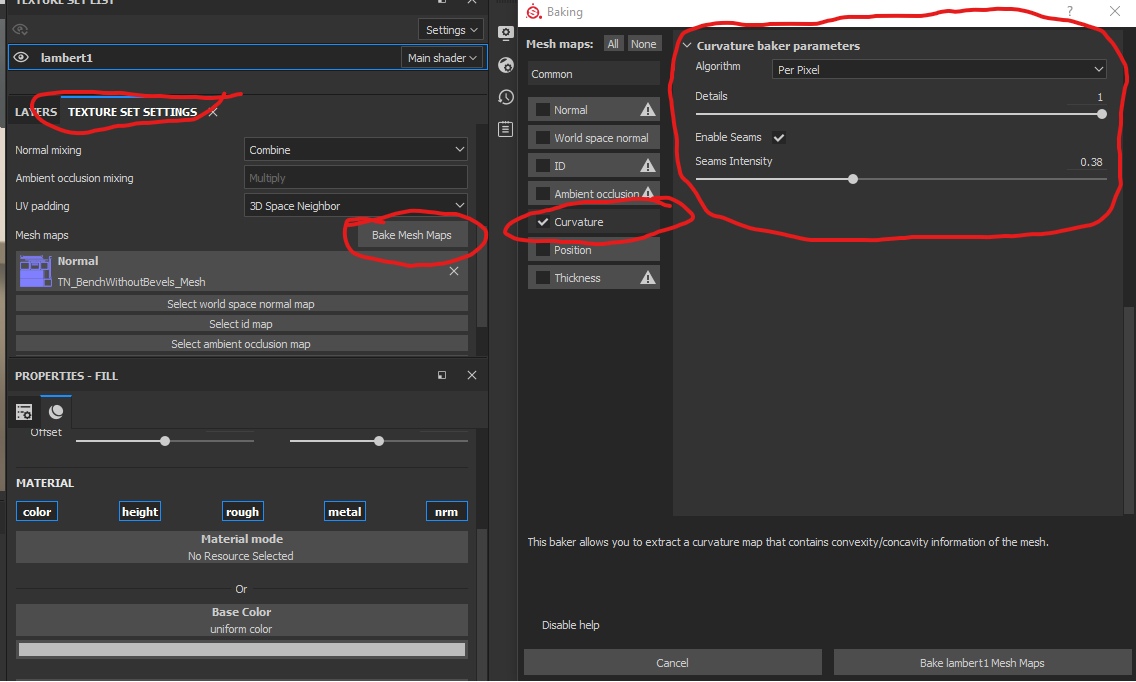
To do this, open the main texture settings (where we indicated the normal map), select Bake Mesh Maps there .
In the window that appears, remove all unnecessary checkmarks, leaving only Curvature and bake it by clicking onBake [additional name] Mesh Maps :
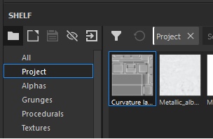
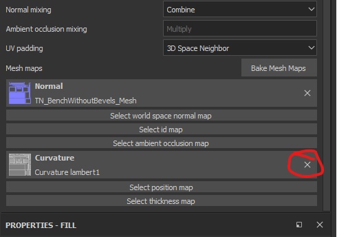
When the texture creation is finished - it will be available in the shelf under the Project tag:
Also, this texture will automatically be connected as the main Curvature parameter in the texture settings. Let's remove it from there:
If we create a new layer at the top of the hierarchy and set the resulting texture as the Base Color parameter, we will see the following result:
Now we will delete this layer, since we needed it exclusively for understanding.
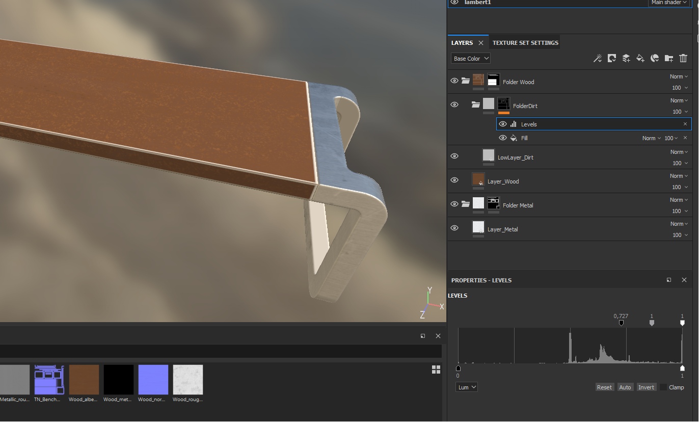
Next, create a folder, call it Folder Dirt and place it in the tree folder OVER the tree layer. In this folder, create a layer called LowLayer_Dirt, and on the folder itself create a black mask so that the layer does not overlap the result:

We point out that the mud mask should consist of Fill effects to add the texture we created (curvature) and the additional “Levels” effect.
Why do we need the Levels effect now? You probably noticed that the face mask is too light? Now we will need to crop the colors in such a way as to leave light white spots on the edges, and do the rest completely black.
The end result you should get is this:
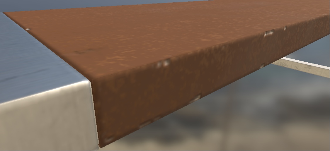
In this way, we created a “ borderline ” for dirt. Now we need to limit the dirt itself. To do this, apply a black mask to the LowLayer_Dirt layer itself. After that, add the Fill effect, and in it specify the Dirt4 mask, which is hidden under the Procedurals tag:

Above in the screenshot, the additional parameters of the Dirt 4 mask are circled. The fact is that this is not a texture in the format in which we are used to presenting it. This is a random number generator according to certain rules. In other words, a procedural texture in which pixels have a generated intensity. You can play around with parameters, for example, twist Balance and Contrast to achieve the desired result. Now change the Height parameter in the LowLayer_Dirt layer to -0.35 and look at the result:
I repeat. Now our goal is not in perfect qualitative painting of the bench, but work with the basics and training to work with masks.
Now homework
In general, we have now examined how to quickly apply masks for specific materials that do not intersect. As you might guess, to apply varnish to a tree - we need to create a layer in the folder with the tree. But now we will not do this, and the task itself remains for homework:
- varnish a tree
- create scratches on the varnish (those scratches that are visible only at an angle, because they push the varnish, but do not damage the wood)
- create scratches under the varnish
Throw your crafts into comments - interestingly =)
Total
We've figured out how to texture models using masks. How to apply dirt, chips and scratches.
So that in the future you have a simple idea of how it all works, remember the rule - one material - one folder for working with it. So you can better control your masks and layers. For example, by placing a layer of dirt in the folder with the material, you still control at the level of the mask of the folder the total visibility of this material, and now also the dirt on it (or the layer below it). For example, in reality, another texture may lie under the texture (material) - plastic can hide under the metal coating. In this case, metal is the main layer, and plastic is the additional layer under the metal (although in the tutorial above we placed the layer with chips and placed above the tree, in fact it is the lower layer in the hierarchy. In other words, this is a mistake).
Layers of materials, their hierarchy must be calculated before you begin to create textures. This is important, because incorrect layouts of the layers can ultimately lead to the fact that you have to start all over again and spend many hours examining why your texture displays only a metal layer.
In general, on this we close the big topic of how to texture objects for games within the framework of PBR. Everything else is technology. My task is to tell the essence, the basis of all this, so that you do not have further questions like “What is the difference between the Roughness card and the Metallic and Normal map?” (I’ll answer right away with nothing), and questions have come up - “How can this be improved? How to do better and more efficiently? ”
We have examined several limitations that have solutions.
- Chamfering.
- Restriction on the location of the islands.
Both restrictions can be circumvented in one way or another. In the first case, we create a normal map that imitates a bend, in the second case we draw islands and sacrifice details (create pulls) for the sake of the big picture.
In the second case, you also need to remember the directions of the islands - they need to be deployed in a consistent manner, like the direction of the pattern in the materials. Otherwise, the difficulties described above will arise.
Scan
Set aside for the time being Substance Painter. Do not close the project, it will come in handy later when we will export textures to Unreal Engine 4.
In this piece of tutorials we will consider the sweep of objects, the density of the islands and finally study the phenomenon of texel density.
And start with texel.
Texel
Texel is a texture pixel (ba-dum-s).
Density of texel and islands
In order not to confuse a monitor pixel (a physical element of the real world, which is always a fixed size) with a texture pixel (a visualized square that can change its size on the monitor screen and generally distort as a whole), the texture pixel is called texel (Texture and pixel).
There is a fairly complete article on this topic here.. And the translation is here .
However, we will once again consider this phenomenon, because in the future, if we do not realize the whole idea of texels, then it will be difficult for us to work further. And even more so it will be difficult to become a surface artist.
From this moment, we begin to speak correctly - a pixel and a texel. Pixel is a monitor element. Texel is a texture element.
So, let’s repeat the past, texel is an imaginary unit of information display. It exists only in numbers (an array of numbers from various channels), but to make it easier for us to work with render parameters, textures were introduced as a visual substitute for arrays of numbers. I think no one would be happy to paint a spaceship with numbers alone, keeping in mind the idea that a texel in row 8 and in column 453 should be 1 less than texel in row 284 and column 112. It's easier to poke a brush in Photoshop.
Renders (visualization systems) read these numbers and display them as squares (texels). Displaying a texel in the form of a square is a conditional matter. And it depends in particular on the density and tension of the model sweep islands.
We will talk about the density of the sweep islands a little later, but now we’ll deal with the tension of the islands.
Imagine a piece of fabric (if it is difficult to imagine, take any piece of fabric that can be stretched). In a calm state, the pattern (or material pattern) on it remains unchanged, as the manufacturer intended. But if we begin to stretch the fabric, then the pattern will begin to stretch as well. The same effect occurs when we stretch (or compress) the model's scan island:
The scan of the left and right sides is located like this:
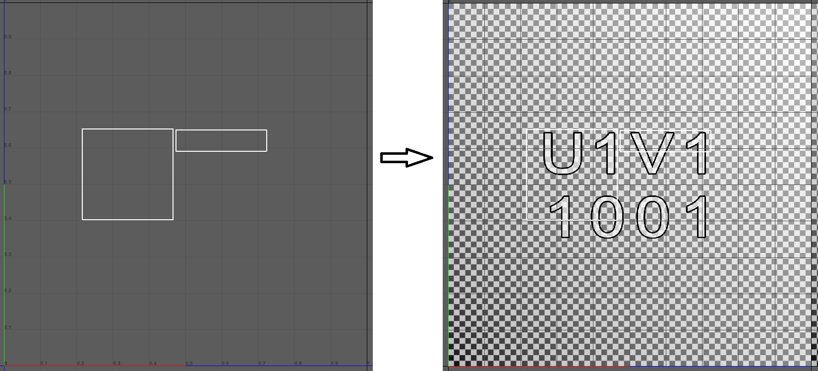
An example shows that, having compressed the representation (island) of the left side, we stretched the texels so that now they are displayed on the left side of the cube in the form of rectangular elongated sticks. That is, the texel on an object depends on how that object is unwrapped. Often in 3D-editors of objects there is an opportunity to trace how tightly the island of development is compressed or stretched. For example, in Autodesk Maya, it looks like this:
Where red shows strong compression, and blue - stretch.
Island density
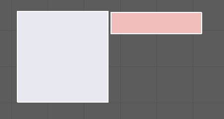
The sweep island should correctly straighten without creating screeds. Still the islands should be scaled among themselves. That is, the area occupied by the island must correspond to the area of another island. Otherwise, it turns out that one island with a real area of 20 sq. Cm will occupy 20% of the texture space, and an island with a real area of 100 sq. Cm will occupy 5% of the texture space. And from this there will be a disagreement in the display of the number of texels on the island:
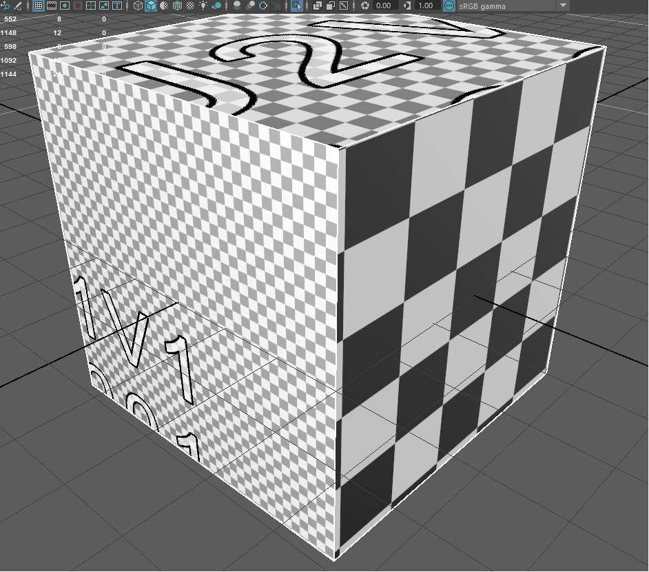
The island on the right side of the cube is very small and can display only 25 texels on which it is located. In this regard, the render increases the texels according to the area of the island, and we see large squares.
On the left, the island is very large - it covers a large piece of texture space and is able to accommodate more texels, which is what happened on the screen. The upper side has an average size.
That is, in order for the model to be correctly textured, you need to align the area of all the islands so that they are equal in relation to each other:
Above is a picture from the article of the habrochanin Osmandos . His article is here . Recommended reading.
Texture Size
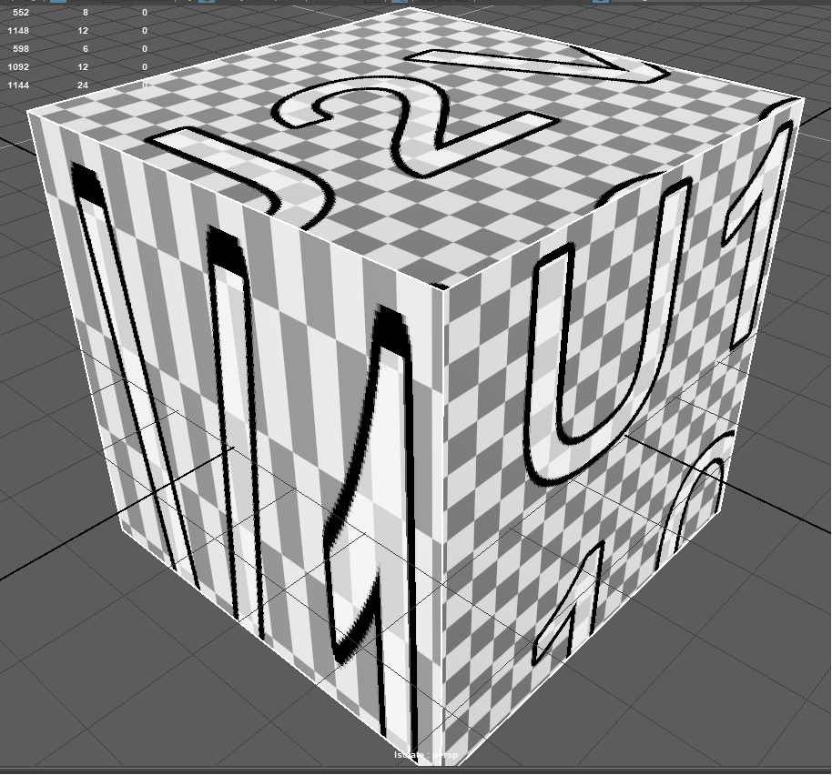
If we return to our cube, we will see that the texels on it (black and white squares, in this example) are very large (again, conditionally. Imagine that in the current texture the squares are texels). Even if we align all the islands, we still see black and white squares on the sides of the cube:
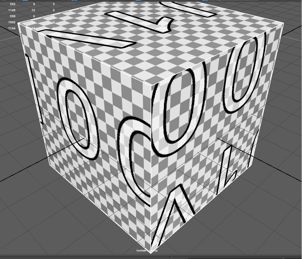
This tells us that the current texture size is not of high enough quality, so we see texels. But is it?
Imagine that the current texture (it is usually called a “Checker” - a texture for checking the correct island settings) has a dimension of 63 by 63 texels. And now we see texels because the object is located so close to our camera that the size of one texel occupies an area of 30x30 pixels of the monitor (conditionally).
And if we move the cube away from the camera?
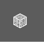
Try to make out texels on this cube now?
Now 1 texel is equal in size to 1 pixel (but this is not accurate). And the size of such a texture is ideal, since it allows you to display all your texels, and also does not display anything superfluous and does not hide anything superfluous. This is the ideal size for such a distance.
That is, the size of the texture depends very much on the area occupied by the model sweep and on the distance of the object to the camera. If the object is located at a sufficiently large distance from us, there is no point in giving it 8k textures on the nail. Even if you make textures for the film, no one will just see a white strip on the nail of a girl whose hand occupies 3% of the screen area.
Total
It is important to understand the scale of the models and where they will be located relative to the camera in order to correctly size the textures. Very often I saw games from indie developers who neglected these simple rules, and as a result their textures were not of the best quality.
Do not forget to align the islands relative to each other - this is important and greatly affects perception. If you open, for example, the game Fallout 4 and start a dialogue with some NPS, you will notice that the quality of the textures on the character’s clothes leaves much to be desired, and the face has the maximum texture size:
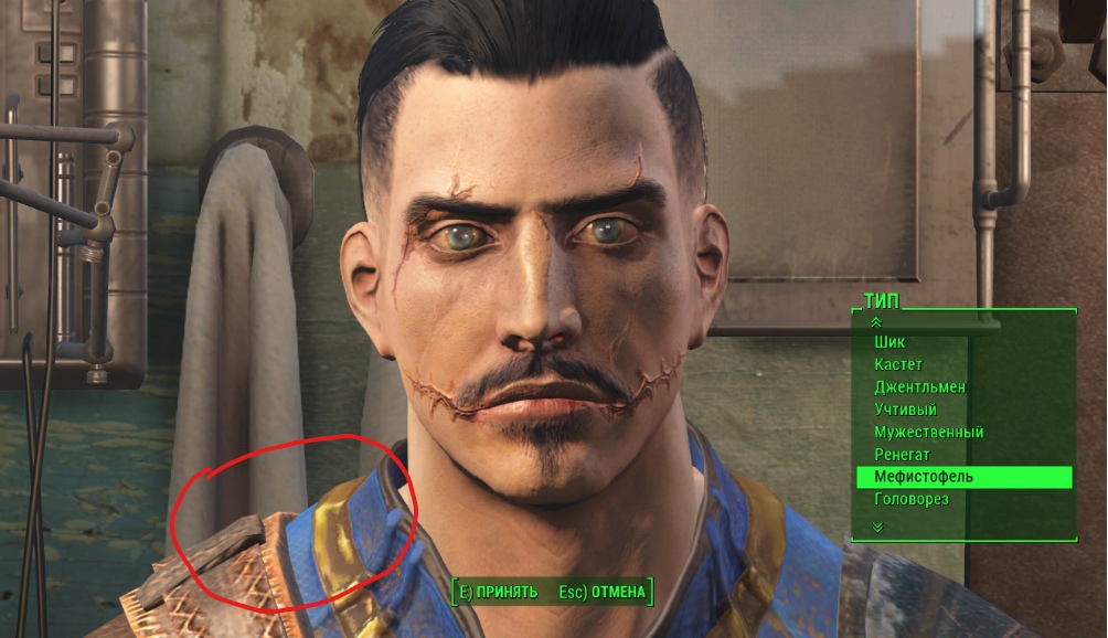
It is worth remembering that in games often the texture size is specially underestimated in for performance. And who looks at clothes when a character has such an interesting face with scars?
Large sizes of textures occupy a large space (in memory, I mean). Therefore, many developers make a difficult decision - what to cut, and what to leave, if only the game does not slow down on your PC / console / phone. However, we will return to this issue and consider the latest techniques that allow us to avoid such troubles.
Texture baking
What is texture baking?
Texture baking is when a package for creating textures begins to calculate the final result and save it in separate files, with the help of which the model is then painted in the game engine.
Roughly speaking, in Substance Painter we apply layers after layers through masks and other tricks to achieve the final result. We are working on how the final model should look, mixing various options of materials. But, if you notice - the more difficult your combination of layers, masks and materials will be, the more difficult it will be to process your changes to the program. The fact is that Substance Painter (any other texturing program) checks your every change and calculates in real time ALL the layers and channels you created (and I remind you that you can also add your own channels to layers for anything-anything ) that fall on texel.
And when we are satisfied with the result and are ready to upload it to the game engine, we ask Substance Painter to make the last calculations and create a texture with parameters for the color of each pixel, and 3 additional textures with Metallic, Roughness and Normal Map parameters. This will allow us not to upload tons of masks and additional materials into the game, not to force the engine to re-calculate everything, but simply provide it with a finished result, which it will convert to textures for the model.
In general, we figured out baking textures. However, we need to see how the parameters are unloaded into the textures so that we learn how we can control which texture channels will go to which data. This is important because there are still only 4 channels in image standards. And we need to be able to choose which channel which parameters will go to, so that we can then quickly connect them.
Now we return to Substance Painter, in our project, and begin to unload textures. To do this, open the window for unloading textures (File - Export textures):
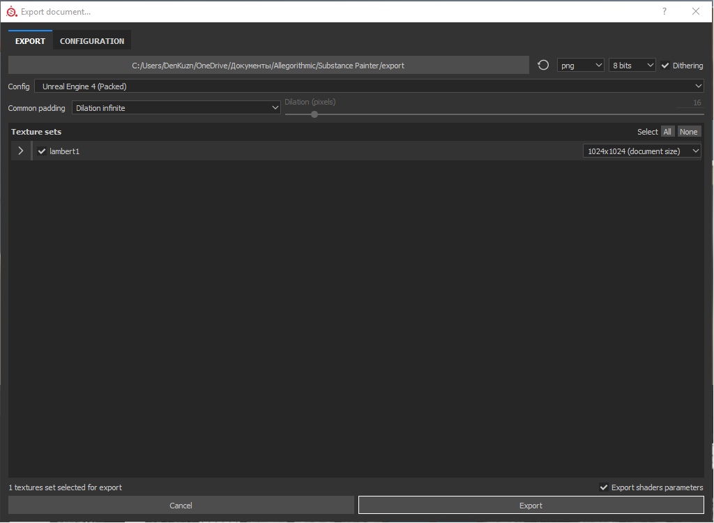
This is how it looks initially. If we expand the texture set, we will see a list of files that will be uploaded as an export:
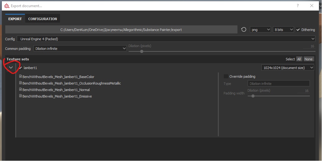
As you can see, there are 4 texture files that should be exported, against the 9 files that we downloaded.
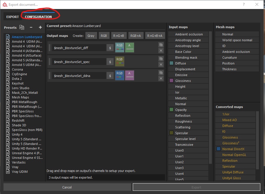
But they don’t interest us, because they are standard settings, but we need our own ones (or according to the standard of the studio in which you work). Therefore, we will go to the Configuration window :
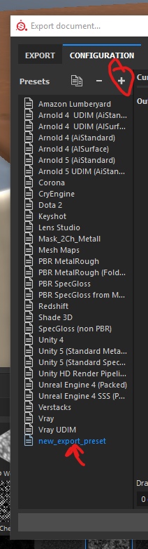
First, create new presets and select them so as not to knock down the finished ones:
Now, pay attention to the panel on the right:
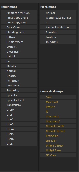
Input Maps is a list of channels that we used. Most of them have names, as they are used for PBR for specific purposes. There are 8 channels (0 to 7) that are editable, but Substance Painter does not know why you might need them, so the channels have the standard names User0 - User7.
Converted maps- This is a list of textures that depend on the type of render. For example, Normal Map depends on the engine. And we need to know which API the engine uses - DirectX or OpenGL, in order to select the correct normal map for it. Therefore, Substance Painter selects these cards in a separate category, as their final result will depend on what you choose.
Mesh Maps - those textures that you loaded with the object or generated while working on it. We downloaded 9 textures. 8 of them belonged to layers (materials), and the 9th normal map for bevels was already directly related to the object. In addition to the normal map, we also created a Curvature map for overlaying chips on it. These cards relate specifically to the object and cannot be used as the basis for materials, therefore they are put in a separate list.
Now consider the texture creation panel:
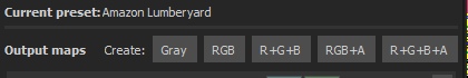
These are the buttons, by clicking on which you create 1 texture file (more precisely, prepare everything for its creation).
Gray - creates a texture with a single channel. In this channel we can place any of our settings - Roughness, metallic, specular, emissive. All those settings that work in one channel.
RGB - creates a texture with 3 connected channels. That is, it is intended for such parameters as color (BaseColor), normal map. That is, for all parameters that use 3 channels for the full realization of themselves.
R + G + B- creates a texture with 3 unconnected channels. That is, we have a texture with three Gray channels. We can specify a parameter with 1 channel in each texture channel separately. This is often used for ORM - (Occlusion-Roughness-Metallic). That is, Ambient Occlusion is stored in the first channel, Roughness is stored in the second, and Metallic in the third.
RGB + A - you guessed it - 3 connected channels and 1 not connected.
R + G + B + A - four unconnected channels.
Now, knowing this, think about how many files we need to upload all the information about how the final texture for the object should look.
That's right, at least 3 textures:
- RGB - BaseColor
- R + G + B - ORM
- RGB - Normal Map
Click on the textures you need one by one, and you will get the following list:
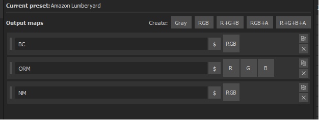
Do not forget to name the textures correctly, otherwise we won’t figure out what where and how.
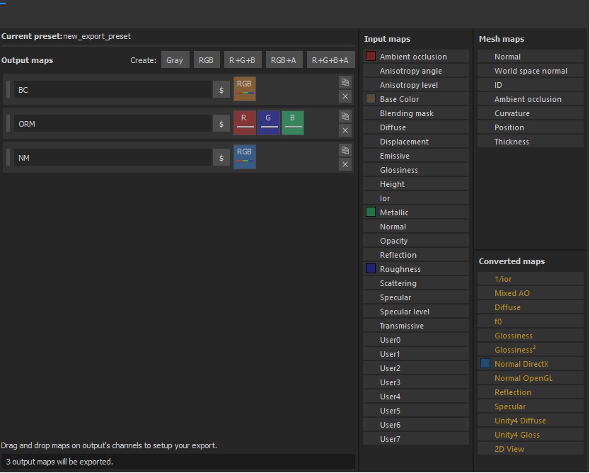
Now we need to indicate which parameters in which channels will be stored. To do this, simply transfer the parameters from the Input Maps to the desired channels. The normal map needs to be migrated to DirectX, since UE4 uses this normal reading format.
As a result, we get the following set:
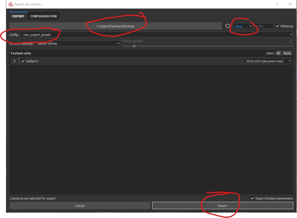
Now switch back to Export. We are there:
- We indicate the path where to save.
- Select the presets we created in the Config options.
- Select the type of texture - Targa.
- Click Export.
And voila - texture export was a success. Open the BC (BaseColor) texture in Photoshop and look at it:
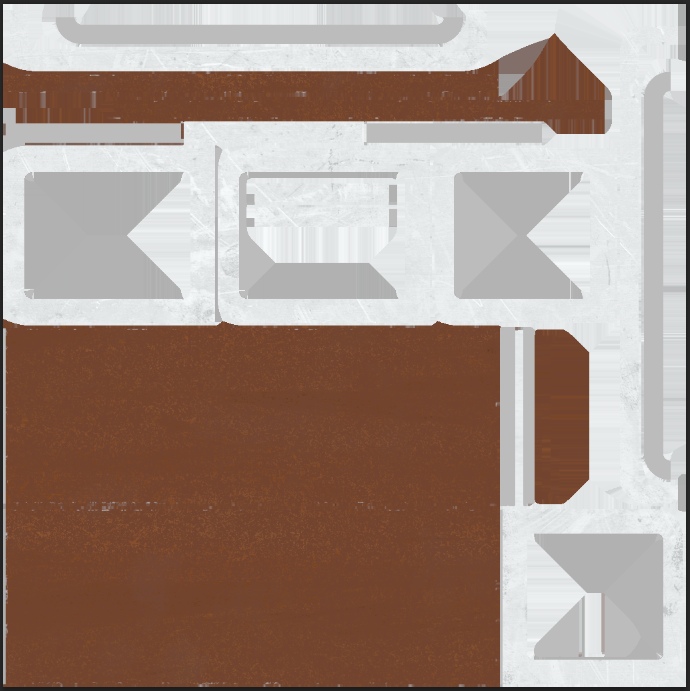
Do you remember how we created 2 different materials in different layers? Substance Painter folded all the layers, calculated the result of the final version of the texture that will cover the object, and “baked” all texels exactly as you masked them. He did the same with Normal Map, Roughness, and Metallic.
If we open the ORM map in Photoshop, go to the channel display mode and select the last (blue), then we will see the baked Metallic map:
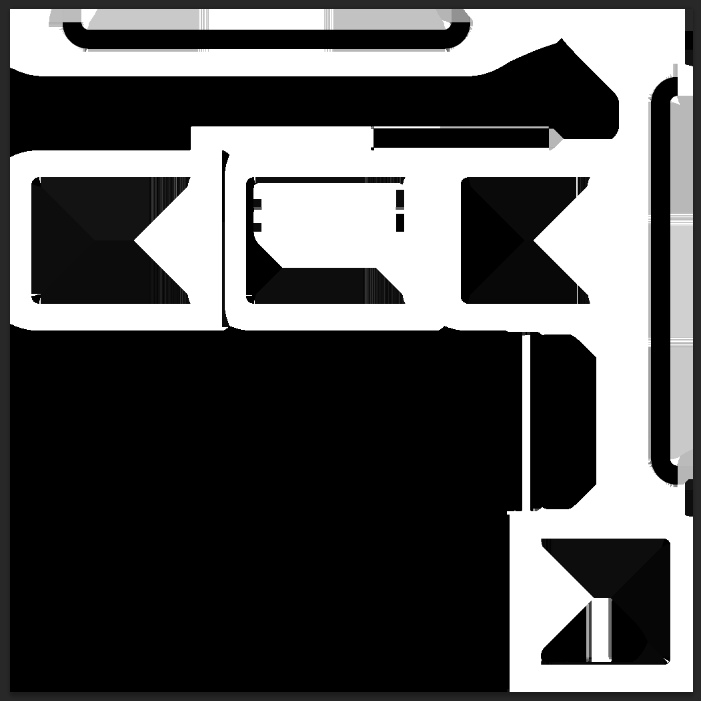
From this map you can imagine where the islands should be metal and where not metal.
Total
We learned how to create ready-made textures for the game engine.
Important. Now we have learned how to bake textures, doing the whole calculation of creating these textures in Substance Painter. That is, we did everything to get ready-made textures, which we can now use in different engines (subject to processing of some PBR parameters). The downside of this approach - if we need to radically change something - we have to return to the program and redo the textures.
To calculate how to correctly display the color and light from a texel - the video card needs to make calculations for each texel. And it will not depend on how many pixels you have on the monitor. This will depend on how many texels are used in the formation of the texture (in the interest we use standard settings, which means we use 1024 * 1024 texels). That is, to display the texture correctly, the painter needs to count every pixel, and take into account all the layers that you created in it. This is a time-consuming task, so earlier (and now) PBR textures were created mainly in texturing programs.
Unreal engine 4
And lastly, unload our object in UE4 and see our result. I will not describe how to open UE4, how to create a project, how to install it at all, and what buttons to press there. There are very good courses from Flakky for this . Courses are all located on his website uengine.ru .
Now we will consider only the import of our shop and the resulting textures, the creation of a primitive shader and to summarize.
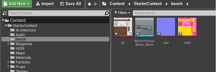
First, open the project and create a “Bench” folder in it, into which we will drop all our textures and the object. To import all textures - just transfer them from the browser to the project. They are imported without any problems and will not ask for additional settings. As for the object, when importing it, Unreal Engine will ask you to specify some settings. In general, nothing needs to be changed except 2 parameters. They must be disabled:

These parameters are responsible for importing textures, and they are separately stored with us.
As a result, in our folder there are 3 textures and 1 object:
Now in any free space in the project browser, click RMB and select Material:
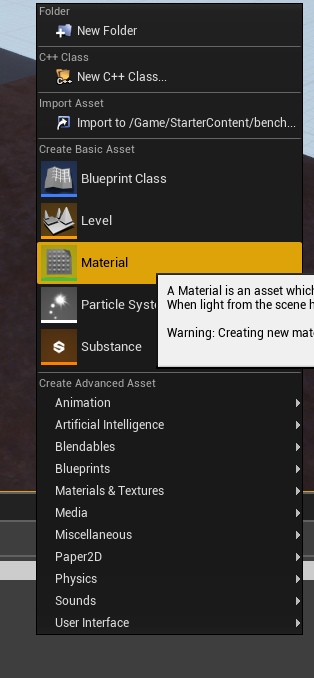
Name it M_Bench.
Open it and drag all of our textures into it. We get the following picture:
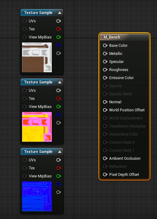
These are Node containers that allow you to visualize settings so that it is convenient for even a novice to work with them (many thanks for the successful implementation of Epic Games nodes. Without Blueprints systems and nodes in particular, many would have burned heads from numbers and code). White pins (outputs and inputs) on the textures (nodes on the left) indicate that three channels are fed at once. But red, green and blue - each channel separately. The last grayish one is the alpha channel, but it is not in our textures, so we will not use this pin. On the right is a large node that takes in the parameters, summarizes them and creates a complete material.
The whole principle of texture work in Substance Painter is used here (and in any other game engine) - you indicate what parameters are needed for what, and the program gives the result. In this case, Substance Painter took over most of the calculations, while the Unreal Engine simply adds up the finished results of Painter and creates a ready-made shader (material) that can be put on the bench.
We only need to connect the pins correctly and ask the engine to calculate the result for us:
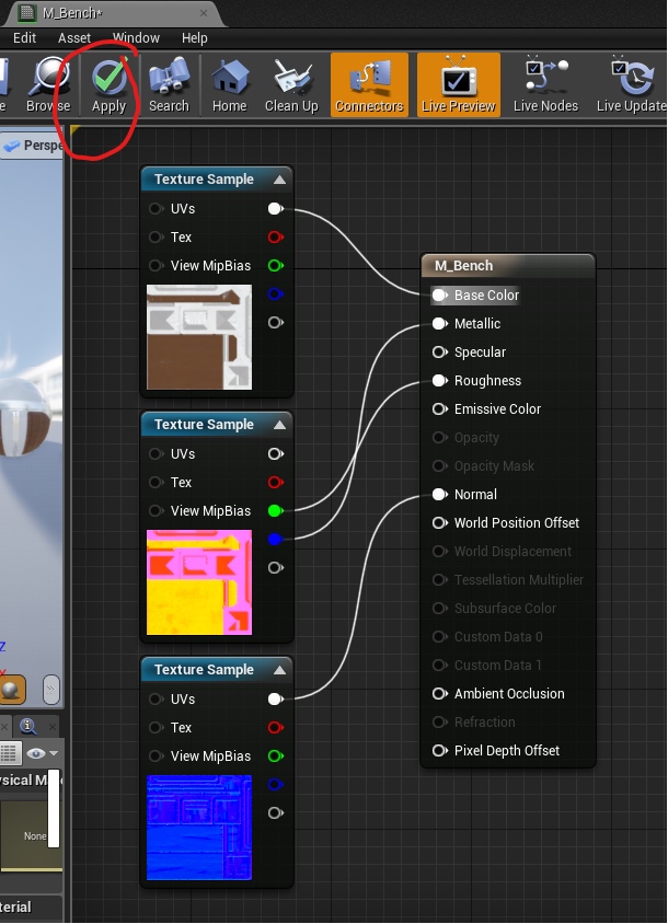
Why didn't I stick a red channel from the ORM texture in Ambient Occlusion? I already mentioned that AO is considered obsolete, since AO is often calculated in real time. And in the material node there is an Ambient Occlusion pin, but it does not work. It is not even taken into account. Left here for some reason. I suppose that a sufficiently large amount of work is required to remove it.
So. We have the simplest shader (material) ready, and we can finally paint our shop. To do this, open a store in UE4 by clicking on it 2 times with LMB. And drag the material from the project browser into the material slot:
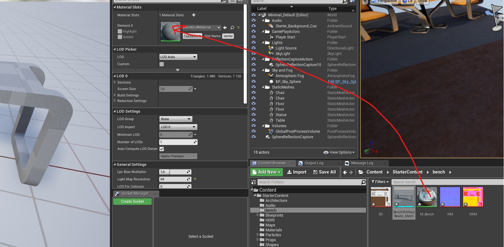
Well. Now you have received your first finished object.
You can see the result yourself, but I will only summarize.
Total
In a very simple way, we learned how to create the first shaders in the UE4 engine. You ask - why is it called Material, and not a shader in the engine itself? It’s easier to explain what kind of texture building format this is - this is the material that is superimposed on the object, and the object becomes beautiful. But the possibilities of shaders are much greater (much, hundreds of times more) than just showing textures.
Offtop. Solving Chamfer Issues
Above, I identified the problem with chamfers and how to solve it. But there is a second way, which we will not fully consider in this part - this is creating chamfers on the model and aligning the normals so that the surface of the mesh creates the illusion of a beautiful bevel. Such a chamfer is created by aligning the normals of the vertices (tangents). And this method is even somewhat more economical for performance than the method with normal maps, and its level of beauty is extremely high relative to the usual texturing of chamfers. Here is an example of a door that is standing in one of our game projects (not yet announced):
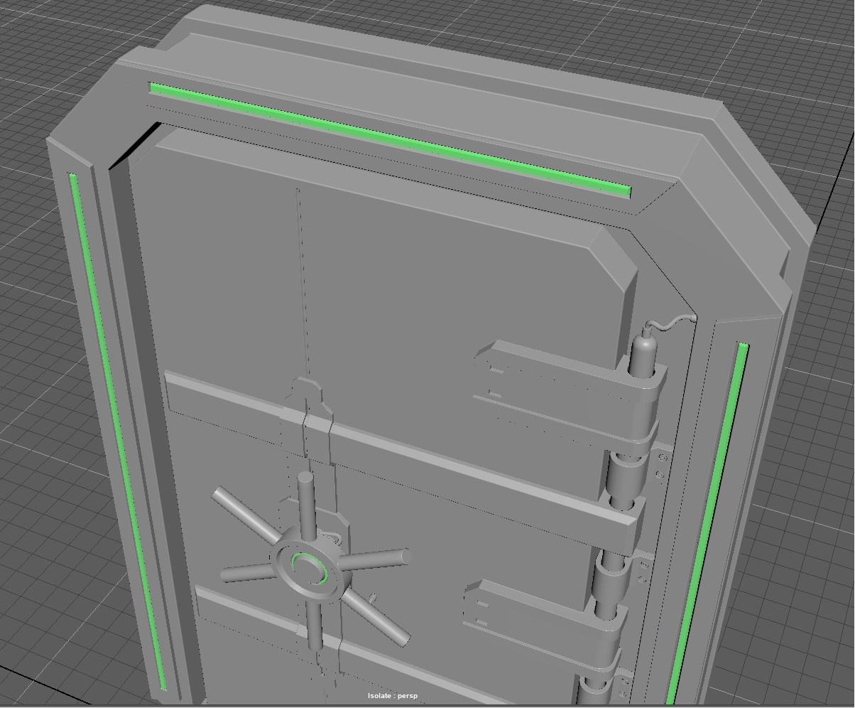
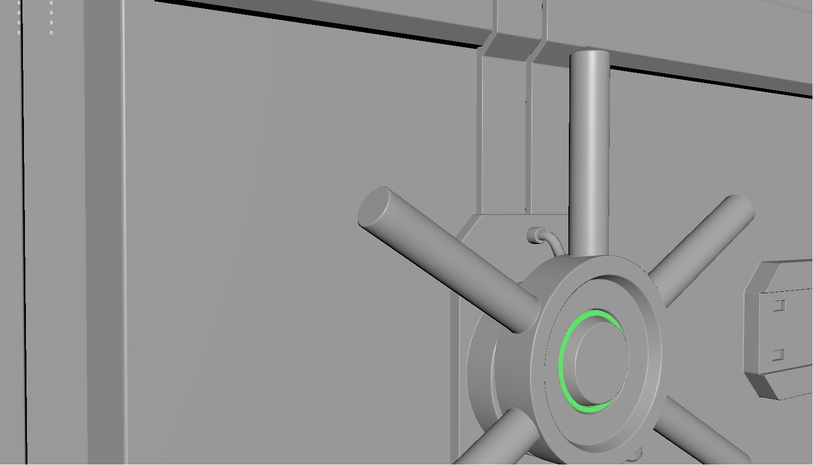
I came across information about this topic only on English-speaking resources. Here .
The advantage of this method is that we create a beautiful facet, while the number of vertices does not increase much, since hard edges are always 2 vertexes at one point, and soft edges are 1 vertex, and the number increases triangles for drawing:
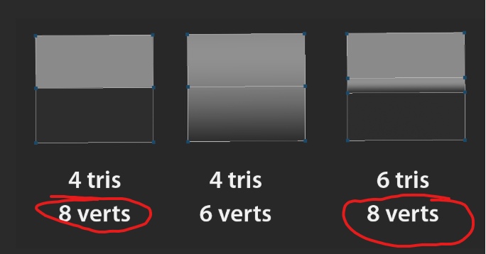
It is worth remembering that we need a normal map for an object in 99% of cases to create chamfers. And normal maps for materials and some individual elements are a slightly different topic.
Total
Ooooooh. Well, the big part is this one. But it was necessary to fully cover the topic of standard texturing. And on this we can stop.
Well, the truth is, we have gone from a barely noticeable pixel element on your monitor to complex schemes of masks that determine the visibility of no less complex layers of materials. Finally, we split the word pixel into two - texel and pixel. And we learned to bake and connect all this in the game engine. At this step, you can draw a long bold line and say that we have become real texture artists. Everything else - the beauty of chipping at objects, the cinematography of a visual representation - this is all the accumulation of time and a constant desire to learn new techniques and methods.
You can watch more lessons and improve your skill. For example, in Substance Designer there is a huge anvil of generators, creating which you can use as their layer generators. And all those masks that were for dirt should no longer be created manually, but implemented at the level of functions that will do everything beautifully for you.
You should always remember that we consider the range of values from 0 to 1. This is important because standard textures have 8 bits per channel, and HDR textures have wider channels (from 16 bits or more), which means that the number range is much greater than 0 to 255. But this is still a range from 0 to 1.
And everything seemed to be the limit. We have reached a high level of understanding of how textures are created. You can just drop everything and go to work as a texture artist for any company that shares modeling and texturing (as we do, for example).
But is it? Have we really reached the limit in texturing and will it fail anymore?
Or is there still more to grow?
Yes! And we have one more tutor left, which will take texturing to a new technological leap and, in my humble opinion, will represent the next generation of texturing.