Broadcast projects and libraries from Altium Designer to PADS Professional
- Tutorial
Often, engineers need to translate projects from one CAD to another. In enterprises, it is not uncommon for such a situation when different departments design in different CAD systems. Also, translation of projects may be required when your design system can no longer cope with the tasks and it is necessary to continue development in a more powerful solution.
In this article I will show you that translating a project from Altuim is a fairly simple process.
All the most interesting under the cut.

PADS Professional has a set of translators to help you easily transfer projects and libraries from all popular CAD systems (Allegro, Altium Designer, CADSTAR, OrCAD, P-CAD and Protel).
Today, we will dwell in detail on broadcasting projects and libraries from Altium Designer.
Broadcast Order

- First of all, in order for the translation process to be successful, you need to make sure that the scheme is fully synchronized with the topology in Altium itself. Of course, we can broadcast non-synchronized projects, but this is more likely to lead to errors in the broadcast process.
- After that, we need to create an empty library, into which during the broadcast we will add symbols, footprints and components from our project.
- The next step we will need to list the seats in which the mounting holes are contained and indicate them in a special file.Why is this?.We do this in order to maintain the correct information on the number of pads in the component. Since the translator when translating a footprint, which consists, for example, of 5 pads and 2 mounting holes, converts it into a footprint with 7 pads, if we do not specify these mounting holes in a special file.
- Next, we transmit information about footprints and contact pads to our created library, for this we will use the topology file.
- After that, we broadcast the scheme, as well as all the UGO symbols and information about the components to our library.
- Then we translate the entire topology from Altium.
- And the last and one of the most important, probably, steps, we carry out the project packaging and synchronization of the scheme and topology. In order to ensure that all subsequent changes in the topology or scheme are automatically synchronized with each other, and we are confident in the integrity of the data.
Supported project and library formats
The following file types are supported:
- Diagram files (* .sch) in binary format, as well as in ASCII format, including diagrams stored in the Protel design database (* .ddb)
- Altium Designer PCB Design Files (* .prjpcb)
- Protel 99 library files (* .lib), including circuit libraries stored in the Protel design database (* .ddb)
- Schema files (* .schdoc) in binary format, as well as in ASCII format.
- Library Files (* .schlib and * .intlib)
What do we need for successful broadcasts
- This, in fact, is PADS Professional itself and its license.
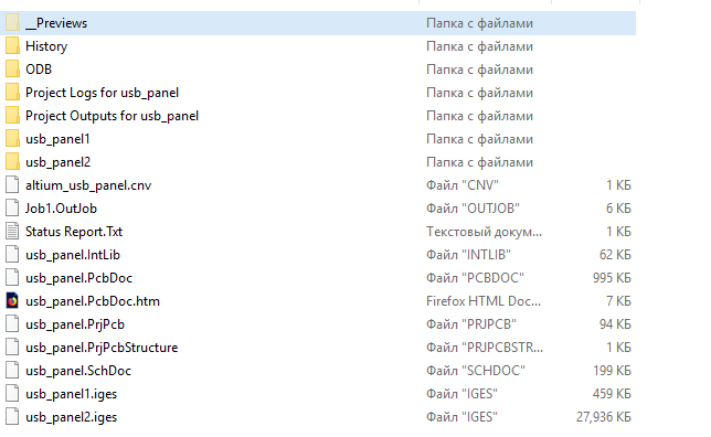
- Of course we need a project in Altuim (* .PrjPcb, * .SchDoc, * .PcbDoc)
- As I said earlier, the project should be synchronized on the side of Altium.
- List of mounting holes that are in the footprints. If it is not there, it’s okay, you can fix it later with your hands, or re-transmit the project again.
Broadcast process
Project synchronization in Altium Designer
And so, first of all, we need the Altium project to be synchronized (compiled). I will not describe the process of compiling the project on the Altium side, since I practically did not work in it myself. The whole process is described in sufficient detail HERE .
Since I do not have an Altium license, I found an already synchronized project.
Creating a project library
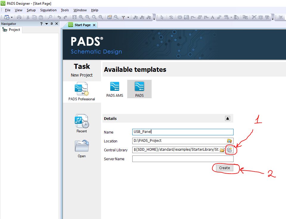
Now we need to create an empty library for our project, for this we launch PADS Designer:
- Go to the tab for creating a new project and first create a library. To do this, click on the appropriate icon, indicate the directory where our library will be stored and give it a name. We will create an empty library and it will have several standard symbols, as well as standard sections.
- Next, indicate the name of the project itself and click Create in order to create a project associated with the library that we just created.
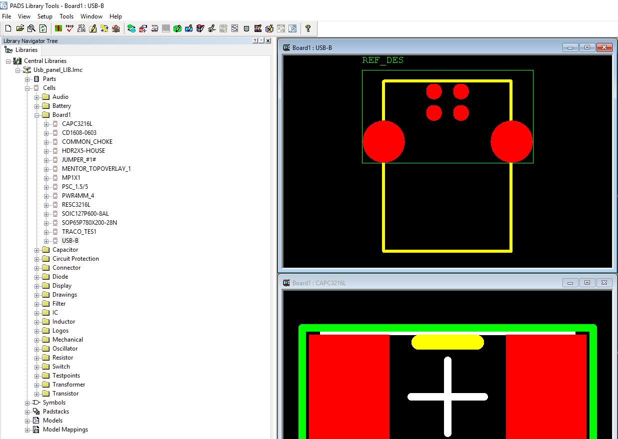
And so we have an empty project, let's open the library (Tools -> PADS Library Tools) and look at it.
We see that the library has automatically created standard sections for symbols, components and footprints, as well as the symbols themselves, such as sheet frames.

Definition of mounting holes
The next step is to determine the footprints that contain the mounting holes and write them in the configuration files.
More details
For the correct translation of footprints containing mounting holes, we will need to edit 2 alt2pads.ini and ppcb2hkp.ini files. These files are located in the installation directory of PADS Professional.
The syntax in these files is as follows: we need to specify the name of the footprint that contains the mounting holes, then list the names of these mounting holes.
If we don’t take this step or do it wrong, we can get such an error with Forward Annotation:

Which tells us that the TO-263 footprint has 4 pads, although only 3 is written in the information on the component itself. This means that when broadcasting, the mounting hole turned into a pad and, accordingly, increased the total number of pads in the footprint.
The syntax in these files is as follows: we need to specify the name of the footprint that contains the mounting holes, then list the names of these mounting holes.
If we don’t take this step or do it wrong, we can get such an error with Forward Annotation:
Which tells us that the TO-263 footprint has 4 pads, although only 3 is written in the information on the component itself. This means that when broadcasting, the mounting hole turned into a pad and, accordingly, increased the total number of pads in the footprint.
- We go to the directory where these files are stored. If you did not change the directory during installation, it will be: C: \ MentorGraphics \ PADSProVX.2.5 \ SDD_HOME \ pads \ win32 \ bin
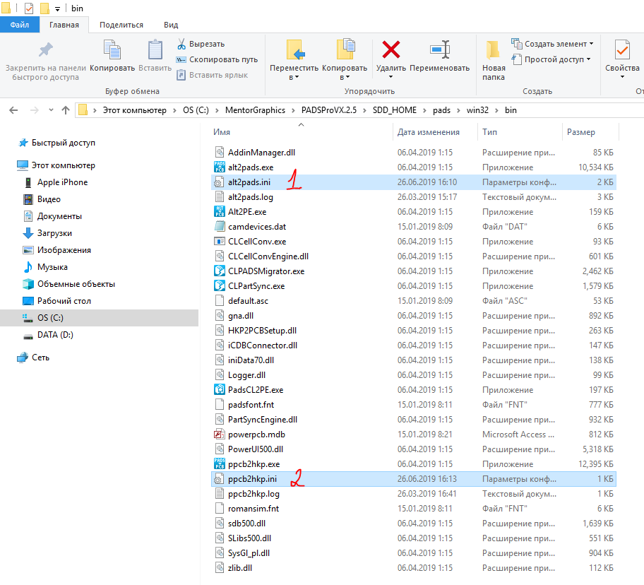
- The first file we need is alt2pads.ini. Let's open it. Here you will see a lot of information, as this file also contains configuration information for other translators. In our case, we are interested in the [Protel mounting Holes] section .
- We need to specify the prefix used to designate the mounting holes. Here already stands the standard version of MH and in this case it suits me. If the mounting holes are marked differently in your projects, you must indicate this here.
- Well and most importantly, we need to list the footprints that contain mounting holes. In my case, this is one footprint. Enter its name PSC 1.5 / 5, then put an equal sign and quote the mounting holes themselves in quotation marks. I have it M1 and M2. If there are still such footprints, then each of them needs to be registered from a new line.
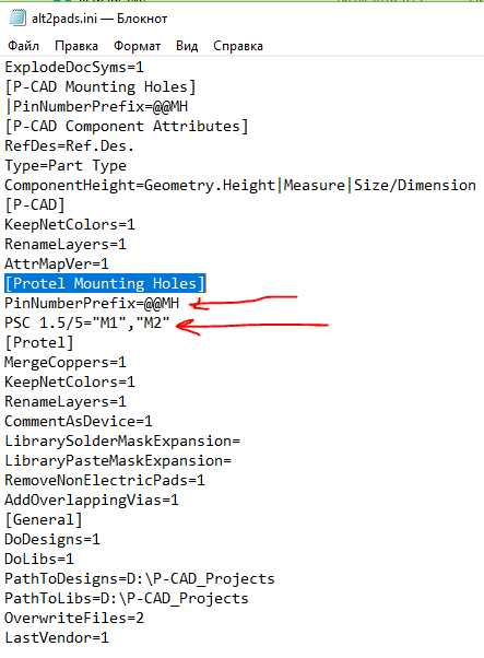
- After editing, do not forget to save the changes (File -> Save).
We need to edit another file, it is ppcb2hkp.ini. We open it and make sure that PinNumberPrefix is specified here exactly the same as we specified in the alt2pads.ini file.
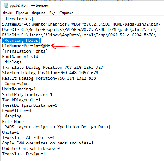
Save the changes and move on.
Why do we specify this data in different configuration files?
Previously, the process of translating projects from Altium to PADS Pro took place in 2 stages:
Starting with version VX2.4, the translator has been updated and now it does this intermediate step automatically in the background. That is, it still translates first to PADS Standard / Standard + then from PADS Standard / Standard + to PADS Pro, but for us for users this all happens in one iteration.
- Broadcast from Altium to PADS Standard / Standard +
- Broadcast from PADS Standard / Standard + to PADS Pro.
Starting with version VX2.4, the translator has been updated and now it does this intermediate step automatically in the background. That is, it still translates first to PADS Standard / Standard + then from PADS Standard / Standard + to PADS Pro, but for us for users this all happens in one iteration.
Returning translators to the start menu
One nuance that I would like to touch upon before starting the translator itself is that starting from VX2.5, Mentor Graphics for some reason removed the translators section from the start menu. If you have PADS Pro VX.2.5 and you need to run one of the translators, you will need to go into the installation directory and find them there, or run through the command line. I will now show a way to return all the shortcuts to the start menu.
- Open the file startmenu.ini through notepad. It is located at C: \ MentorGraphics \ PADSProVX.2.5 \ SDD_HOME \ pads \ win32
- Here we need to uncomment all the lines in this file, for this we need to remove the semicolons at the beginning of each line.
- This is most conveniently done through the replace function (Edit -> Replace). Specify a semicolon in the line what to replace, and leave the second line empty and click replace all. After replacing the file will look like this:

- Save all changes.
- Now we need to re-register the application, for this we go to the start menu and launch the MGC BSD Release Switcher.

- We tick Don’t Unregister Anything , and from the second list select our working version of the PADS PRO VX2.5 application and click OK .
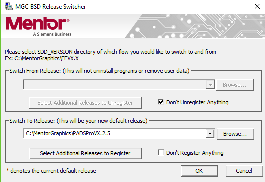
- We are waiting for the application registration process to complete.
- Upon completion, you will see translators in the start menu in the PADS Pro Tools section.
Broadcast footprints and pads
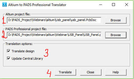
Now we launch the translator in order to broadcast footprints and contact pads to our library. In the translators section, select Altium to PADS Pro

- In the first line we indicate the Altium board file with the PcbDoc extension
- In the second line we indicate the file of the empty DxDesigner project that we created earlier
- Check both Translate Design and Update Central Library, this will automatically create a pcb board project, update our library and add all the pads and footprints from the project there.
- Click Translate .
- We are waiting for the message about the successful broadcast.
- If you see the message “Translation succeeded. Check log for details ”, then everything can move on perfectly.
- You can also look in more detail at the broadcast process by opening the corresponding log. It can be found in the project directory in the PCB -> LogFiles folder. All broadcast operations and their results are listed here. This log can help you if errors occur during the broadcast.
Let's see now how our library has changed.
Open the PADS Library Tools. We are interested in the Cells section and then the board1 subsection, which was automatically created when the board was broadcast, and now it contains all the footprints. You can click on them and see what they broadcast correctly.
Translation of symbol and component diagrams
The next step is the translation of the circuit, UGO symbols and information about the components.
And since we just broadcast the board without associating it with any circuit, this can cause a bunch of errors in the future. We needed this step only to fill our library, therefore, we further perform the following steps:
- We completely delete the folder with our project.
- Launch DxDesigner.
- We create a new clean project with the same name and link it to our already half-filled library.
- Now we are ready to broadcast the scheme
- We start the translator, it is built directly into DxDesigner (menu File -> Import -> Altium).
- In the window that opens, on the Schematics tab, click on the Add button and specify the path to the Altium circuit design with the PrjPcb or SchDoc extension.the noteIf you have a PrjPcb file, this is much better, since it contains all the schematic sheets associated with this project. If it is not there, then it will be necessary to broadcast all the sheets with the SchDoc extension in turn.

- Go to the Settings tab , here you can define the mapping of various attributes, that is, how a particular attribute from Altium will be converted to PADS Pro.Where to get the configuration mapping files?There are already several configuration files with property mapping in the installation directory (C: \ MentorGraphics \ PADSProVX.2.5 \ SDD_HOME \ standard \ cnv \ altium_dx.cnv). They are suitable for most cases, but if any specific attributes are present in your projects, then you can list them manually.
- I want to pay attention to the UseTranlatedCentralLib line in the [CONVERSION] section . Today we will leave it empty, since we have already made a library for a specific project, but if you have Altium corporate library and all projects are built on it, you can specify a link to it here, after broadcasting it.
- Go back to the Schematics tab , click Translate and wait.
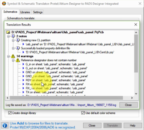
- At the end of the broadcast process, a window will pop up in which the result will be described. Result analysisThe main thing for us here is that there are no Error messages . There may be Warning messages , but they usually do not affect the integrity of the project data. In my case, the translator renamed the name of the GND pins so that they were not duplicated, and assigned them serial numbers.
- We close the translator, and we have a translated circuit.
- Open the project library and check for new characters and component information in it. In the symbols section, a new subsection has been created with the name of the USB panel project itself (in my case). Opening it, you will see all the symbols contained in our project. A similar subsection has also been created in the parts section, we see that each component is associated with a symbol and a seat.

Topology Translation
Now we need to broadcast the board itself. We have already done this today. Let's just repeat the procedure.
- Launch Altium to PADS Pro Translator
- We indicate the path to the file with the PcbDoc extension and the path to the DxDesigner project with which the board will be connected.
- In this case, we need to uncheck Update Central library , since we already have all the seats and padstacks.
- Click Translate and wait for the process to complete.

- Launch PADS Professional Layout (you can do this from the DxDesigner menu Tools -> PADS Professional Layout).
- When PADS Professional Layout loads, you will see a message:

- Click OK
- And one more message:
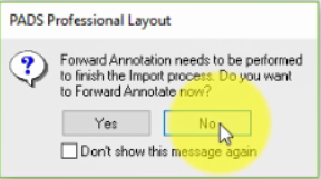
- Click No
- Take a good look at the project and check the translation is correct.
- If all is well, then move on.
Project packaging and synchronization
Let's now open DxDesigner and package the project.
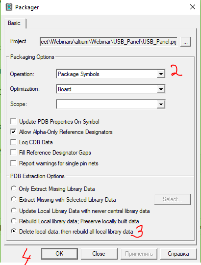
- Go to the Tools -> Package menu
- Select in the operation section - package symbols
- In the PDB Extraction Options section, set Delete local data, then rebuild all local library data .
- Click OK , and look at the result.
- If all is well, you will see the message The iCDB is up to date! in the Output window
Now that we have packaged the project, we need to make a direct annotation of changes in order to synchronize the scheme and topology.
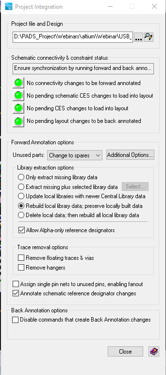
- Go back to Layout and go to the menu Setup -> Project integration.
- We need to make the indicators turn green, then there will be complete synchronization.
- We remove the checkmarks from the Remove floating traces & vias and Remove Hangers options so that the system does not remove any conductors and vias from the project, which may become “hanging in the air” after the broadcast.
- Now click on the yellow indicator and wait.

- If all indicators turn green, then you are lucky! In principle, this can be completed.
In fact, errors are likely to occur, but they are quite easy to fix.
If you want to learn how to fix errors that occur during direct annotation of a project, see my webinar of the same name, the article was written on it:
Sign up for the next HyperLynx DRC webinar - Identifying Problems Affecting Signal, Power, and EMC Integrity .
The project that I used to broadcast can download HERE .
If you need a 30-day license from PADS Professional or any other Mentor Graphics product, you can leave a request in a personal message.
Only registered users can participate in the survey. Please come in.
Rate the usefulness of this material
- 21.4% 1 3
- 0% 2 0
- 7.1% 3 1
- 0% 4 0
- 7.1% 5 1
- 0% 6 0
- 28.5% 7 4
- 7.1% 8 1
- 0% 9 0
- 28.5% 10 4