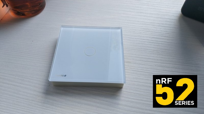
Wireless touch switch with additional fluorescent backlight
Greetings to all readers of the DIY or Do-it-yourself section on Habr! Today's article will be about the touch switch on the TTP223 chip | datasheet . The switch operates on the nRF52832 microcontroller | datasheet , YJ-17103 module with a printed antenna and a connector for an external antenna MHF4 was used. The touch switch is powered by CR2430 or CR2450 batteries. Consumption in transmission mode is not more than 8mA, in sleep mode is not more than 6mA.
Like all previous projects, this one is also an Arduino project, the program is written in the Arduino IDE. The software implementation of the device is based on the Mysensors protocol | GitHub libraries , GitHub support for nRF5 boards in Mysensors. English Community Forum -http://forum.mysensors.org, русскоязычный форум сообщества — http://mysensors.ru/forum/
(Для желающих изучить — Документация, Serial Protocol, API, Протокол, Парсер | для желающих оказать содействие (contributions) в развитии проекта — Документация)
The touch switch board was developed in the Diptrace program, taking into account subsequent manufacturing according to the method of Laser Iron Technology (LUT). The board was developed in sizes of 60x60mm (the standard glass panel has dimensions of 80x80mm). The circuit was printed on the pages of the magazine Antenna and transferred by a Bosch iron with the setting “Len” (maximum power) to a double-sided foil-coated fiberglass plate 1.5mm, 35 µm (for lack of another).

Etching was carried out with a solution of ferric chloride, previously prepared in the proportions of 1.5 parts of a spoon per 250 ml of warm water. The process took 15 minutes.
The holes for the interlayer transitions and for mounting the battery holder were drilled with a DREMEL 3000 mini-drill mounted on a DREMEL 220 drill stand. The holes for the interlayer transitions were drilled with a 0.4 mm drill, the holes for the battery holder with a 1.1 mm drill. Trimming along the board borders was performed with the same mini-drill with a DREMEL 540 nozzle (cutting wheel d = 32.0mm). Cropping was carried out in a respirator.
Tinning of the etched board was performed using a Rose alloy in an aqueous solution (1 teaspoon of crystallized citric acid in 300 ml of water).
The soldering process took about an hour, most of the time was spent on soldering the wire (tinned, 0.4 mm in diameter) in the holes for interlayer transitions.
The board was washed with the FLUX OFF aerosol cleaner.


The development of the device case was performed in a three-dimensional computer-aided design editor. Case dimensions 78.5mm X 78.5mm X 12mm.

The finished model of the housing and the battery cover was saved in STL format, then it was necessary to prepare these models for printing on an SLA printer (adding supports, orientation). At this point, a small problem arose, since the print area of household SLA printers is small. The model of the device’s body in the most optimal position relative to the printing time did not fit in the size of the print area. When placing the model at 45 degrees, it also gave a disappointing result, the support weight was equal to the weight of the case model. It was decided to print the model vertically, making support on one of the front sides, previously agreeing with the fact of post processing. It took 5 hours to seal the case with a 50 micron layer setting. Next, processing was performed using very fine-grained sandpaper (I won’t write the number, since I don’t know :)). The battery cover was printed for 40 minutes.

The glass panels with Aliexpress are sold with an already glued plastic frame, there were no problems removing the frame. I took off pre-heating the glass panel with an ordinary hairdryer.


The diffuser for the LED backlight was made of double-sided tape with 3M 9088-200 acrylic adhesive. For fluorescent lighting, there were several materials to choose from, Chinese adhesive tape and adhesive paper cut into tapes of the domestic company Luminophore. The choice was made in favor of a domestic manufacturer; according to my feelings, it shone brighter and longer. A square made of paper with fluorescent pigment was pasted on top of 3M 9088-200 double-sided tape.
The glass was glued to the switch case using double-sided tape with 3M VHB 4910 acrylic adhesive. The

cover was fixed with a M 1.4 X 5mm screw.
The cost of the device was 890 rubles.
Next came the software part. No problem. It turns out that the TTP223 sensor microcircuits work perfectly with stabilized power at 3.3V and are not very good when powered directly from a well-discharged battery. At the start of the device with power in the region of 2.5v, plus after an additional "drawdown" when working out the Mysensors presentation, the TTP223 chip (immediately after calibration) caused the MC to interrupt because it was with the active trigger.
The circuit for supplying power to the microcircuit (TTP223 power management with gpio MK) was changed, additional ground was supplied, on the rgb led lines (which run on the other side of the capacitive sensor board), resistors with higher resistance were replaced. Also in the software was added: power activation for a capacitive microcircuit after starting the Mysensors framework and working out the presentation. The delay for auto-calibration of the TTP223 chip is doubled when power is applied to it. All these changes completely fixed this problem.
The switch has a touch button and a clock button on the back of the device. This clock button will be used for service modes, air snap mode, zeroing the device. The button implements an iron anti bounce. The capacitive sensor line and the clock button line through the Schottky diodes are connected and connected to the analog pin p0.05, the lines to the p0.25 and p0.27 MK pins go to the capacitive sensor and the clock button to read states after activating the interrupt on p0 pin. 05. On pin p0.05, an interrupt via the comparator (NRF_LPCOMP) by EVENTS_UP is activated. I got inspiration for solving the problem here and here .
The switch was added to the Mysensors network, managed by the controller of the smart home, Magordomo ( project site )

Позднее был сделан вариант с повышающим преобразователем, но это не связанно с работой ёмкостной микросхемы TTP223, тут больше желания в хорошей и равномерной подсветке при отработке нажатий на всем сроке работы от батарейки.
Github проекта — github.com/smartboxchannel/EFEKTA_WIRELESS_TOUCH_SWITCH
Русскоязычный сайт сообщества Mysensors
Телеграмм чат Mysensors — быстрое решение проблем с Mysensors, советы, подсказки, установка плат, работа с микроконтроллерами atmega 328, stm32, nRF5 в среде Arduino IDE — @mysensors_rus
Like all previous projects, this one is also an Arduino project, the program is written in the Arduino IDE. The software implementation of the device is based on the Mysensors protocol | GitHub libraries , GitHub support for nRF5 boards in Mysensors. English Community Forum -http://forum.mysensors.org, русскоязычный форум сообщества — http://mysensors.ru/forum/
(Для желающих изучить — Документация, Serial Protocol, API, Протокол, Парсер | для желающих оказать содействие (contributions) в развитии проекта — Документация)
The touch switch board was developed in the Diptrace program, taking into account subsequent manufacturing according to the method of Laser Iron Technology (LUT). The board was developed in sizes of 60x60mm (the standard glass panel has dimensions of 80x80mm). The circuit was printed on the pages of the magazine Antenna and transferred by a Bosch iron with the setting “Len” (maximum power) to a double-sided foil-coated fiberglass plate 1.5mm, 35 µm (for lack of another).
Etching was carried out with a solution of ferric chloride, previously prepared in the proportions of 1.5 parts of a spoon per 250 ml of warm water. The process took 15 minutes.
The holes for the interlayer transitions and for mounting the battery holder were drilled with a DREMEL 3000 mini-drill mounted on a DREMEL 220 drill stand. The holes for the interlayer transitions were drilled with a 0.4 mm drill, the holes for the battery holder with a 1.1 mm drill. Trimming along the board borders was performed with the same mini-drill with a DREMEL 540 nozzle (cutting wheel d = 32.0mm). Cropping was carried out in a respirator.
Tinning of the etched board was performed using a Rose alloy in an aqueous solution (1 teaspoon of crystallized citric acid in 300 ml of water).
The soldering process took about an hour, most of the time was spent on soldering the wire (tinned, 0.4 mm in diameter) in the holes for interlayer transitions.
The board was washed with the FLUX OFF aerosol cleaner.
The development of the device case was performed in a three-dimensional computer-aided design editor. Case dimensions 78.5mm X 78.5mm X 12mm.
The finished model of the housing and the battery cover was saved in STL format, then it was necessary to prepare these models for printing on an SLA printer (adding supports, orientation). At this point, a small problem arose, since the print area of household SLA printers is small. The model of the device’s body in the most optimal position relative to the printing time did not fit in the size of the print area. When placing the model at 45 degrees, it also gave a disappointing result, the support weight was equal to the weight of the case model. It was decided to print the model vertically, making support on one of the front sides, previously agreeing with the fact of post processing. It took 5 hours to seal the case with a 50 micron layer setting. Next, processing was performed using very fine-grained sandpaper (I won’t write the number, since I don’t know :)). The battery cover was printed for 40 minutes.
The glass panels with Aliexpress are sold with an already glued plastic frame, there were no problems removing the frame. I took off pre-heating the glass panel with an ordinary hairdryer.
The diffuser for the LED backlight was made of double-sided tape with 3M 9088-200 acrylic adhesive. For fluorescent lighting, there were several materials to choose from, Chinese adhesive tape and adhesive paper cut into tapes of the domestic company Luminophore. The choice was made in favor of a domestic manufacturer; according to my feelings, it shone brighter and longer. A square made of paper with fluorescent pigment was pasted on top of 3M 9088-200 double-sided tape.
The glass was glued to the switch case using double-sided tape with 3M VHB 4910 acrylic adhesive. The
cover was fixed with a M 1.4 X 5mm screw.
The cost of the device was 890 rubles.
Next came the software part. No problem. It turns out that the TTP223 sensor microcircuits work perfectly with stabilized power at 3.3V and are not very good when powered directly from a well-discharged battery. At the start of the device with power in the region of 2.5v, plus after an additional "drawdown" when working out the Mysensors presentation, the TTP223 chip (immediately after calibration) caused the MC to interrupt because it was with the active trigger.
The circuit for supplying power to the microcircuit (TTP223 power management with gpio MK) was changed, additional ground was supplied, on the rgb led lines (which run on the other side of the capacitive sensor board), resistors with higher resistance were replaced. Also in the software was added: power activation for a capacitive microcircuit after starting the Mysensors framework and working out the presentation. The delay for auto-calibration of the TTP223 chip is doubled when power is applied to it. All these changes completely fixed this problem.
Before viewing the program code, I recommend that you familiarize yourself with the basic structure of sketches in Mysensors.
void before()

{

 // Дополнительная функция, если сравнивать со стандартной структурой Ардуино скетчей, то before() это подобие setup(), отработка происходит до инициализации транспортного уровня Mysensors, рекомендуется например для инициализации устройств SPI

}


void setup()

{


}


void presentation()

{

 //Тут происходит презентация ноды и ее сенсоров на контролере через маршрутизатор

 sendSketchInfo("Name of my sensor node", "1.0"); // презентация названия ноды, версии ПО

 present(CHILD_ID, S_WHATEVER, "Description"); // презентация сенсоров ноды, описания сенсоров

}


void loop()

{


}
Test code for touch switch program:
test_sens.ino
MyBoardNRF5.cpp
MyBoardNRF5.h
/**

 ТЕСТОВЫЙ СКЕТЧ СЕНСОРНОГО ВЫКЛЮЧАТЕЛЯ С ПРЕРЫВАНИЯМИ НА NRF_LPCOMP

*/

bool button_flag;

bool sens_flag;

bool send_flag;

bool detection;

bool nosleep;

byte timer;

unsigned long SLEEP_TIME = 21600000; //6 hours

unsigned long oldmillis;

unsigned long newmillis;

unsigned long interrupt_time;

unsigned long SLEEP_TIME_W;

uint16_t currentBatteryPercent;

uint16_t batteryVoltage = 0;

uint16_t battery_vcc_min = 2400;

uint16_t battery_vcc_max = 3000;


#define MY_RADIO_NRF5_ESB

//#define MY_PASSIVE_NODE

#define MY_NODE_ID 30

#define MY_PARENT_NODE_ID 0

#define MY_PARENT_NODE_IS_STATIC

#define MY_TRANSPORT_UPLINK_CHECK_DISABLED

#define IRT_PIN 3 //(PORT0, gpio 5)

#include

// see https://www.mysensors.org/download/serial_api_20

#define SENS_CHILD_ID 0

#define CHILD_ID_VOLT 254

MyMessage sensMsg(SENS_CHILD_ID, V_VAR1);

//MyMessage voltMsg(CHILD_ID_VOLT, V_VOLTAGE);


void preHwInit() {

 sleep(2000);

 pinMode(RED_LED, OUTPUT);

 digitalWrite(RED_LED, HIGH);

 pinMode(GREEN_LED, OUTPUT);

 digitalWrite(GREEN_LED, HIGH);

 pinMode(BLUE_LED, OUTPUT);

 digitalWrite(BLUE_LED, HIGH);

 pinMode(MODE_PIN, INPUT);

 pinMode(SENS_PIN, INPUT);

}


void before()

{

 NRF_POWER->DCDCEN = 1;

 NRF_UART0->ENABLE = 0;

 sleep(1000);

 digitalWrite(BLUE_LED, LOW);

 sleep(150);

 digitalWrite(BLUE_LED, HIGH);

}


void presentation() {

 sendSketchInfo("EFEKTA Sens 1CH Sensor", "1.1");

 present(SENS_CHILD_ID, S_CUSTOM, "SWITCH STATUS");

 //present(CHILD_ID_VOLT, S_MULTIMETER, "Battery");

}


void setup() {

 digitalWrite(BLUE_LED, LOW);

 sleep(100);

 digitalWrite(BLUE_LED, HIGH);

 sleep(200);

 digitalWrite(BLUE_LED, LOW);

 sleep(100);

 digitalWrite(BLUE_LED, HIGH);

 lpComp();

 detection = false;

 SLEEP_TIME_W = SLEEP_TIME;

 pinMode(31, OUTPUT);

 digitalWrite(31, HIGH);

 /*

 while (timer < 10) {

 timer++;

 digitalWrite(GREEN_LED, LOW);

 wait(5);

 digitalWrite(GREEN_LED, HIGH);

 wait(500);

 }

 timer = 0;

 */

 sleep(7000);

 while (timer < 3) {

 timer++;

 digitalWrite(GREEN_LED, LOW);

 sleep(15);

 digitalWrite(GREEN_LED, HIGH);

 sleep(85);

 }

 timer = 0;

 sleep(1000);

}


void loop() {


if (detection) {

 if (digitalRead(MODE_PIN) == 1 && button_flag == 0 && digitalRead(SENS_PIN) == 0) {

 //back side button detection

 button_flag = 1;

 nosleep = 1;

 }

 if (digitalRead(MODE_PIN) == 1 && button_flag == 1 && digitalRead(SENS_PIN) == 0) {

 digitalWrite(RED_LED, LOW);

 wait(10);

 digitalWrite(RED_LED, HIGH);

 wait(50);

 }

 if (digitalRead(MODE_PIN) == 0 && button_flag == 1 && digitalRead(SENS_PIN) == 0) {

 nosleep = 0;

 button_flag = 0;

 digitalWrite(RED_LED, HIGH);

 lpComp_reset();

 }


if (digitalRead(SENS_PIN) == 1 && sens_flag == 0 && digitalRead(MODE_PIN) == 0) {

 //sens detection

 sens_flag = 1;

 nosleep = 1;

 newmillis = millis();

 interrupt_time = newmillis - oldmillis;

 SLEEP_TIME_W = SLEEP_TIME_W - interrupt_time;

 if (send(sensMsg.set(detection))) {

 send_flag = 1;

 }

 }

 if (digitalRead(SENS_PIN) == 1 && sens_flag == 1 && digitalRead(MODE_PIN) == 0) {

 if (send_flag == 1) {

 while (timer < 10) {

 timer++;

 digitalWrite(GREEN_LED, LOW);

 wait(20);

 digitalWrite(GREEN_LED, HIGH);

 wait(30);

 }

 timer = 0;

 } else {

 while (timer < 10) {

 timer++;

 digitalWrite(RED_LED, LOW);

 wait(20);

 digitalWrite(RED_LED, HIGH);

 wait(30);

 }

 timer = 0;

 }

 }

 if (digitalRead(SENS_PIN) == 0 && sens_flag == 1 && digitalRead(MODE_PIN) == 0) {

 sens_flag = 0;

 nosleep = 0;

 send_flag = 0;

 digitalWrite(GREEN_LED, HIGH);

 sleep(500);

 lpComp_reset();

 }

 if (SLEEP_TIME_W < 60000) {

 SLEEP_TIME_W = SLEEP_TIME;

 sendBatteryStatus();

 }

 }

 else {

 //if (detection == -1) {

 SLEEP_TIME_W = SLEEP_TIME;

 sendBatteryStatus();

 }

 if (nosleep == 0) {

 oldmillis = millis();

 sleep(SLEEP_TIME_W);

 }

}


void sendBatteryStatus() {

 wait(20);

 batteryVoltage = hwCPUVoltage();

 wait(2);


if (batteryVoltage > battery_vcc_max) {

 currentBatteryPercent = 100;

 }

 else if (batteryVoltage < battery_vcc_min) {

 currentBatteryPercent = 0;

 } else {

 currentBatteryPercent = (100 * (batteryVoltage - battery_vcc_min)) / (battery_vcc_max - battery_vcc_min);

 }


sendBatteryLevel(currentBatteryPercent, 1);

 wait(2000, C_INTERNAL, I_BATTERY_LEVEL);

 //send(powerMsg.set(batteryVoltage), 1);

 //wait(2000, 1, V_VAR1);

}


void lpComp() {

 NRF_LPCOMP->PSEL = IRT_PIN;

 NRF_LPCOMP->ANADETECT = 1;

 NRF_LPCOMP->INTENSET = B0100;

 NRF_LPCOMP->ENABLE = 1;

 NRF_LPCOMP->TASKS_START = 1;

 NVIC_SetPriority(LPCOMP_IRQn, 15);

 NVIC_ClearPendingIRQ(LPCOMP_IRQn);

 NVIC_EnableIRQ(LPCOMP_IRQn);

}


void s_lpComp() {

 if ((NRF_LPCOMP->ENABLE) && (NRF_LPCOMP->EVENTS_READY)) {

 NRF_LPCOMP->INTENCLR = B0100;

 }

}


void r_lpComp() {

 NRF_LPCOMP->INTENSET = B0100;

}


#if __CORTEX_M == 0x04

#define NRF5_RESET_EVENT(event) \

 event = 0; \

 (void)event

#else

#define NRF5_RESET_EVENT(event) event = 0

#endif


extern "C" {

 void LPCOMP_IRQHandler(void) {

 detection = true;

 NRF5_RESET_EVENT(NRF_LPCOMP->EVENTS_UP);

 NRF_LPCOMP->EVENTS_UP = 0;

 MY_HW_RTC->CC[0] = (MY_HW_RTC->COUNTER + 2);

 }

}


void lpComp_reset () {

 s_lpComp();

 detection = false;

 NRF_LPCOMP->EVENTS_UP = 0;

 r_lpComp();

}
#ifdef MYBOARDNRF5

#include


/*

 * Pins descriptions. Attributes are ignored by arduino-nrf5 variant.

 * Definition taken from Arduino Primo Core with ordered ports

 */

const PinDescription g_APinDescription[]=

{

 { NOT_A_PORT, 0, PIO_DIGITAL, PIN_ATTR_DIGITAL, No_ADC_Channel, NOT_ON_PWM, NOT_ON_TIMER}, // LFCLK

 { NOT_A_PORT, 1, PIO_DIGITAL, PIN_ATTR_DIGITAL, No_ADC_Channel, NOT_ON_PWM, NOT_ON_TIMER}, // LFCLK

 { PORT0, 2, PIO_DIGITAL, (PIN_ATTR_DIGITAL|PIN_ATTR_PWM), ADC_A0, PWM4, NOT_ON_TIMER},

 { PORT0, 3, PIO_DIGITAL, (PIN_ATTR_DIGITAL|PIN_ATTR_PWM), ADC_A1, PWM5, NOT_ON_TIMER},

 { PORT0, 4, PIO_DIGITAL, (PIN_ATTR_DIGITAL|PIN_ATTR_PWM), ADC_A2, PWM6, NOT_ON_TIMER},

 { PORT0, 5, PIO_DIGITAL, (PIN_ATTR_DIGITAL|PIN_ATTR_PWM), ADC_A3, PWM7, NOT_ON_TIMER},

 { PORT0, 6, PIO_DIGITAL, PIN_ATTR_DIGITAL, No_ADC_Channel, NOT_ON_PWM, NOT_ON_TIMER}, // INT3

 { PORT0, 7, PIO_DIGITAL, PIN_ATTR_DIGITAL, No_ADC_Channel, NOT_ON_PWM, NOT_ON_TIMER}, // INT4

 { PORT0, 8, PIO_DIGITAL, (PIN_ATTR_DIGITAL|PIN_ATTR_PWM), No_ADC_Channel, PWM10, NOT_ON_TIMER}, //USER_LED

 { PORT0, 9, PIO_DIGITAL, PIN_ATTR_DIGITAL, No_ADC_Channel, NOT_ON_PWM, NOT_ON_TIMER}, // NFC1

 { PORT0, 10, PIO_DIGITAL, PIN_ATTR_DIGITAL, No_ADC_Channel, NOT_ON_PWM, NOT_ON_TIMER}, // NFC2

 { PORT0, 11, PIO_DIGITAL, PIN_ATTR_DIGITAL, No_ADC_Channel, NOT_ON_PWM, NOT_ON_TIMER}, // TX

 { PORT0, 12, PIO_DIGITAL, PIN_ATTR_DIGITAL, No_ADC_Channel, NOT_ON_PWM, NOT_ON_TIMER}, // RX

 { PORT0, 13, PIO_DIGITAL, PIN_ATTR_DIGITAL, No_ADC_Channel, NOT_ON_PWM, NOT_ON_TIMER}, // SDA

 { PORT0, 14, PIO_DIGITAL, PIN_ATTR_DIGITAL, No_ADC_Channel, NOT_ON_PWM, NOT_ON_TIMER}, // SCL

 { PORT0, 15, PIO_DIGITAL, PIN_ATTR_DIGITAL, No_ADC_Channel, NOT_ON_PWM, NOT_ON_TIMER}, // SDA1

 { PORT0, 16, PIO_DIGITAL, PIN_ATTR_DIGITAL, No_ADC_Channel, NOT_ON_PWM, NOT_ON_TIMER}, // SCL1

 { PORT0, 17, PIO_DIGITAL, PIN_ATTR_DIGITAL, No_ADC_Channel, NOT_ON_PWM, NOT_ON_TIMER}, // TP4

 { PORT0, 18, PIO_DIGITAL, PIN_ATTR_DIGITAL, No_ADC_Channel, NOT_ON_PWM, NOT_ON_TIMER}, // TP5

 { PORT0, 19, PIO_DIGITAL, PIN_ATTR_DIGITAL, No_ADC_Channel, NOT_ON_PWM, NOT_ON_TIMER}, // INT2

 { PORT0, 20, PIO_DIGITAL, PIN_ATTR_DIGITAL, No_ADC_Channel, NOT_ON_PWM, NOT_ON_TIMER}, // INT1

 { PORT0, 21, PIO_DIGITAL, PIN_ATTR_DIGITAL, No_ADC_Channel, NOT_ON_PWM, NOT_ON_TIMER}, // INT1

 { PORT0, 22, PIO_DIGITAL, (PIN_ATTR_DIGITAL|PIN_ATTR_PWM), No_ADC_Channel, PWM9, NOT_ON_TIMER},

 { PORT0, 23, PIO_DIGITAL, (PIN_ATTR_DIGITAL|PIN_ATTR_PWM), No_ADC_Channel, PWM8, NOT_ON_TIMER},

 { PORT0, 24, PIO_DIGITAL, PIN_ATTR_DIGITAL, No_ADC_Channel, NOT_ON_PWM, NOT_ON_TIMER}, // INT

 { PORT0, 25, PIO_DIGITAL, (PIN_ATTR_DIGITAL|PIN_ATTR_PWM), No_ADC_Channel, PWM11, NOT_ON_TIMER}, //RED_LED

 { PORT0, 26, PIO_DIGITAL, (PIN_ATTR_DIGITAL|PIN_ATTR_PWM), No_ADC_Channel, PWM11, NOT_ON_TIMER}, //GREEN_LED

 { PORT0, 27, PIO_DIGITAL, (PIN_ATTR_DIGITAL|PIN_ATTR_PWM), No_ADC_Channel, PWM11, NOT_ON_TIMER}, //BLUE_LED

 { PORT0, 28, PIO_DIGITAL, (PIN_ATTR_DIGITAL|PIN_ATTR_PWM), ADC_A4, PWM3, NOT_ON_TIMER},

 { PORT0, 29, PIO_DIGITAL, (PIN_ATTR_DIGITAL|PIN_ATTR_PWM), ADC_A5, PWM2, NOT_ON_TIMER},

 { PORT0, 30, PIO_DIGITAL, (PIN_ATTR_DIGITAL|PIN_ATTR_PWM), ADC_A6, PWM1, NOT_ON_TIMER},

 { PORT0, 31, PIO_DIGITAL, (PIN_ATTR_DIGITAL|PIN_ATTR_PWM), ADC_A7, PWM0, NOT_ON_TIMER}

};


// Don't remove this line

#include


#endif
#ifndef _MYBOARDNRF5_H_

#define _MYBOARDNRF5_H_


#ifdef __cplusplus

extern "C"

{

#endif // __cplusplus


// Number of pins defined in PinDescription array

#define PINS_COUNT (32u)

#define NUM_DIGITAL_PINS (32u)

#define NUM_ANALOG_INPUTS (8u)

#define NUM_ANALOG_OUTPUTS (8u)


/*

 * LEDs

 *

 * This is optional

 *

 * With My Sensors, you can use

 * hwPinMode() instead of pinMode()

 * hwPinMode() allows to use advanced modes like OUTPUT_H0H1 to drive LEDs.

 * https://github.com/mysensors/MySensors/blob/development/drivers/NRF5/nrf5_wiring_constants.h

 *

 */

#define PIN_LED1 (16)

#define PIN_LED2 (15)

#define PIN_LED3 (17)

#define RED_LED (PIN_LED1)

#define GREEN_LED (PIN_LED2)

#define BLUE_LED (PIN_LED3)

#define INTERRUPT_PIN (5)

#define MODE_PIN (25)

#define SENS_PIN (27)


/*

 * Analog ports

 *

 * If you change g_APinDescription, replace PIN_AIN0 with

 * port numbers mapped by the g_APinDescription Array.

 * You can add PIN_AIN0 to the g_APinDescription Array if

 * you want provide analog ports MCU independed, you can add

 * PIN_AIN0..PIN_AIN7 to your custom g_APinDescription Array

 * defined in MyBoardNRF5.cpp

 */

static const uint8_t A0 = ADC_A0;

static const uint8_t A1 = ADC_A1;

static const uint8_t A2 = ADC_A2;

static const uint8_t A3 = ADC_A3;

static const uint8_t A4 = ADC_A4;

static const uint8_t A5 = ADC_A5;

static const uint8_t A6 = ADC_A6;

static const uint8_t A7 = ADC_A7;


/*

 * Serial interfaces

 *

 * RX and TX are required.

 * If you have no serial port, use unused pins

 * CTS and RTS are optional.

 */

#define PIN_SERIAL_RX (11)

#define PIN_SERIAL_TX (12)


#ifdef __cplusplus

}

#endif


#endif
The switch has a touch button and a clock button on the back of the device. This clock button will be used for service modes, air snap mode, zeroing the device. The button implements an iron anti bounce. The capacitive sensor line and the clock button line through the Schottky diodes are connected and connected to the analog pin p0.05, the lines to the p0.25 and p0.27 MK pins go to the capacitive sensor and the clock button to read states after activating the interrupt on p0 pin. 05. On pin p0.05, an interrupt via the comparator (NRF_LPCOMP) by EVENTS_UP is activated. I got inspiration for solving the problem here and here .
The switch was added to the Mysensors network, managed by the controller of the smart home, Magordomo ( project site )
PHP код для добавление в метод statusUpdate выключателя
if (getGlobal("MysensorsButton01.status")==1) {
if (getGlobal('MysensorsRelay04.status') == 0) {
setGlobal('MysensorsRelay04.status', '1');
} else if (getGlobal('MysensorsRelay04.status') == 1) {
setGlobal('MysensorsRelay04.status', '0');
}
}
Результат смотрите на видео
Позднее был сделан вариант с повышающим преобразователем, но это не связанно с работой ёмкостной микросхемы TTP223, тут больше желания в хорошей и равномерной подсветке при отработке нажатий на всем сроке работы от батарейки.
Посмотреть

Github проекта — github.com/smartboxchannel/EFEKTA_WIRELESS_TOUCH_SWITCH
Русскоязычный сайт сообщества Mysensors
Телеграмм чат Mysensors — быстрое решение проблем с Mysensors, советы, подсказки, установка плат, работа с микроконтроллерами atmega 328, stm32, nRF5 в среде Arduino IDE — @mysensors_rus
Немного фоток


