We write under FPGA without HDL. Comparison of high-level development tools
Recently, FPGA manufacturers and third-party companies have been actively developing development methods for FPGAs that differ from conventional approaches using high-level development tools.
As an FPGA developer, I use Verilog's hardware description language ( HDL ) as the main tool , but the growing popularity of new methods aroused my great interest, so in this article I decided to make out what was happening.
This article is not a guide or instruction for use, this is my review and conclusions about what various high-level development tools can give to an FPGA developer or programmer who wants to plunge into the world of FPGA. In order to compare the most interesting development tools in my opinion, I wrote several tests and analyzed the results. Under the cut - what came of it.
Now many are attracted by the idea of high-level development. Both enthusiasts, such as, for example, Quokka and the Python code generator , and corporations, such as Mathworks , and FPGA manufacturers Intel and Xilinx,
each use their own methods and tools to achieve this. Enthusiasts in the struggle for a perfect and beautiful world use their favorite development languages, such as Python or C #. Corporations, trying to please the client, offer their own or adapt existing tools. Mathworks offers its own HDL coder tool for generating HDL code from m-scripts and Simulink models, while Intel and Xilinx offer compilers for common C / C ++.
At the moment, companies with significant financial and human resources have achieved greater success, while enthusiasts are somewhat behind. This article will be devoted to the consideration of the product HDL coder from Mathworks and HLS Compiler from Intel.
Let's start comparing HDL coder from Mathworks and Intel HLS Compiler, having solved several problems using different approaches.
The solution to this problem has no practical value, but is well suited as a first test. The function takes 4 parameters, multiplies the first with the second, the third with the fourth and adds the results of the multiplication. Nothing complicated, but let's see how our subjects cope with this.
To solve this problem, the m-script looks as follows:
Let's see what Mathworks offers us to convert code to HDL.
I will not examine in detail the work with HDL-coder, I will focus only on those settings that I will change in the future to get different results in FPGA, and the changes of which will have to be considered by a MATLAB programmer who needs to run his code in FPGA.
So, the first thing to do is set the type and range of input values. There are no familiar char, int, float, double in FPGA. The bit depth of the number can be any, it is logical to choose it based on the range of input values that you plan to use.
Picture 1
MATLAB checks the types of variables, their values and selects the correct bit depths for buses and registers, which is really convenient. If there are no problems with bit depth and typing, you can proceed to the following points. Figure 2 There are several tabs in the HDL Code Generation where you can choose the language to convert to (Verilog or VHDL); code style names of signals. The most interesting tab, in my opinion, is Optimization, and I will experiment with it, but later, for now, let's leave all the defaults and see what happens with the HDL coder “out of the box”. Press the Run button and get the following code:
The code looks good. MATLAB understands that writing the entire expression on a single line on Verilog is bad practice. Creates separate wires for the multiplier and adder, there’s nothing to complain about.
It is alarming that the description of the registers is missing. This happened because we did not ask HDL-coder about this, and left all the fields in the settings to their default values.
Here is what Quartus synthesizes from such code.

Figure 3
No problems, everything was as planned.
In FPGA we implement synchronous circuits, and still I would like to see the registers. HDL-coder offers a mechanism for placing registers, but where to place them is up to the developer. We can place the registers at the input of the multipliers, at the output of the multipliers in front of the adder, or at the output of the adder.
To synthesize the examples, I chose the FPGA Cyclone V family, where special DSP blocks with built-in adders and multipliers are used to implement arithmetic operations. The DSP block looks like this: Figure 4
DSP block has input and output registers. There is no need to try to snap the results of multiplication in the register before addition, this will only violate the architecture (in certain cases, this option is possible and even needed). It is up to the developer to decide how to deal with the input and output register based on the latency requirements and the required maximum frequency. I decided to use only the output register. In order for this register to be described in the code generated by the HDL-coder, in the Options tab in the HDL coder you need to check the Register output checkbox and restart the conversion.
It turns out the following code:
As you can see, the code has fundamental differences compared to the previous version. An always-block appeared, which is a description of the register (just what we wanted). For the always-block operation, the inputs of the clk module (clock frequency) and reset (reset) also appeared. It can be seen that the output of the adder is latched in the trigger described in always. There are also a couple of ena permission signals, but they are not very interesting to us.
Let's look at the diagram that Quartus now synthesizes.

Figure 5
Again, the results are good and expected.
The table below shows the table of used resources - we keep it in mind.

Figure 6
For this first assignment, Mathworks receives a credit. Everything is not complicated, predictable and with the desired result.
I described in detail a simple example, provided a diagram of a DSP block and described the possibilities of using the register usage settings in HDL-coder, which are different from the “default” settings. This is done for a reason. By this, I wanted to emphasize that even in such a simple example, when using HDL-coder, knowledge of the FPGA architecture and the fundamentals of digital circuitry is necessary, and the settings must be changed consciously.
Let's try to compile code with the same functionality written in C ++ and see what is eventually synthesized in FPGA using the HLS compiler.
So C ++ code
I selected data types to avoid overflowing variables.
There are advanced methods for setting bit depths, but our goal is to test the ability to assemble functions written in C / C ++ style under FPGA without making any changes, all out of the box.
Since the HLS compiler is a native tool of Intel, we collect the code with a special compiler and check the result immediately in Quartus.
Let's look at the circuit that Quartus synthesizes.

Figure 7
The compiler created the input and output registers, but the essence is hidden in the wrapper module. We begin to deploy the wrapper and ... see more, more and more nested modules.
The structure of the project looks like this. Figure 8 An obvious hint from Intel: “don't get your hands on it!”. But we will try, especially the functionality is not complicated.

In the depths of the Project Tree | quartus_compile | TwoMultAdd: TwoMultAdd_inst | TwoMultAdd_internal: twomultadd_internal_inst | TwoMultAdd_fu
nction_wrapper: TwoMultAdd_internal | TwoMultAdd_function: theTwoMultAdd_function | bb_TwoMultAdd_B1_start:
thebb_TwoMultAdd_B1_start | bb_TwoMultAdd_B1_start_stall_region: thebb_TwoMultAdd_B1_start_stall_region | i
_sfc_c1_wt_entry_twomultadd_c1_enter_twomultadd: thei_sfc_c1_wt_entry_twomultadd_c1_enter_twomultad
d_aunroll_x | i_sfc_logic_c1_wt_entry_twomultadd_c1_enter_twomultadd13: thei_sfc_logic_c1_wt_entry_twom
ultadd_c1_enter_twomultadd13_aunroll_x | mult1 is desired module.
We can look at the diagram of the desired module synthesized by Quartus. Figure 9 What conclusions can be drawn from this scheme.
It can be seen that something happened that we tried to avoid when working in MATLAB: the case at the output of the multiplier was synthesized - this is not very good. It can be seen from the DSP block diagram (Figure 4) that there is only one register at its output, which means that each multiplication will have to be done in a separate block.
The table of used resources shows what this leads to.

Figure 10
Compare the results with the HDL coder table (Figure 6).
If using a larger number of registers you can put up with, then spending precious DSP blocks on such a simple functionality is very unpleasant.
But there is a huge plus in Intel HLS compared to HDL coder. With the default settings, the HLS compiler developed a synchronous design in FPGA, although it expended more resources. Such an architecture is possible, it is clear that Intel HLS is configured to achieve maximum performance, and not to save resources.
Let's see how our subjects behave with more complex projects.
This function is widely used in image processing: the so-called “matrix filter” . We sell it using high-level tools.
Work immediately begins with a limitation. HDL Coder cannot accept 2-D matrix functions as inputs. Considering that MATLAB is a tool for working with matrices, this is a serious blow to the entire inherited code, which can become a serious problem. If the code is written from scratch, this is an unpleasant feature that must be considered. So you have to deploy all the matrices into a vector and implement the functions taking into account the input vectors.
The code for the function in MATLAB is as follows
The generated HDL code turned out to be very bloated and contains hundreds of lines, so I will not give it here. Let's see what scheme Quartus synthesizes from this code. Figure 11 This circuit looks unsuccessful. Formally, it is working, but I assume that it will work at a very low frequency, and it can hardly be used in real hardware. But any assumption must be verified. To do this, we will place the registers at the input and output of this circuit and with the help of Timing Analyzer we will evaluate the real situation. To conduct the analysis, you must specify the desired operating frequency of the circuit so that Quartus knows what to strive for when wiring, and in case of failure, provides reports of violations. We set the frequency to 100 MHz, let's see what Quartus can squeeze out of the proposed circuit.
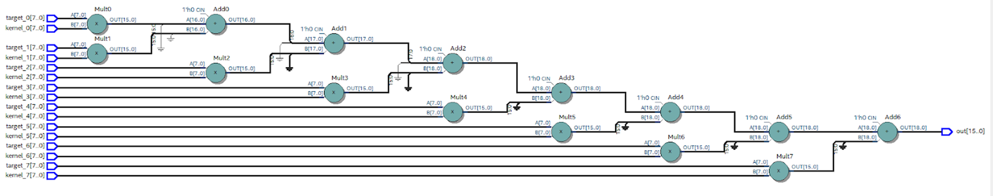

Figure 12
It can be seen that it turned out a little: 33 MHz look frivolous. The delay in the chain of multipliers and adders is about 30 ns. To get rid of this “bottleneck”, you need to use the conveyor: insert registers after arithmetic operations, thereby reducing the critical path.
HDL coder gives us this opportunity. In the Options tab, you can set Pipeline variables. Since the code in question is written in the MATLAB style, there is no way to pipe variables (except mult and summ variables), which does not suit us. It is necessary to insert the registers into the intermediate circuits hidden in our HDL code.
Moreover, the situation with optimization could be worse. For example, nothing prevents us from writing code
it is quite adequate for MATLAB, but completely deprives us of the possibility of optimizing HDL.
The next way out is to edit the code by hand. This is a very important point, as we refuse to inherit and begin to rewrite the m-script, and NOT in the MATLAB style.
The new code is as follows
In Quartus, we collect the code generated by the HDL Coder. It can be seen that the number of layers with primitives has decreased, and the scheme looks much better. Figure 12 With the correct arrangement of primitives, the frequency increases almost 3 times, up to 88 MHz. Figure 13 Now the final touch: in the Optimization settings, specify summ_1, summ_2 and summ_3 as elements of the pipeline. We collect the resulting code in Quartus. The scheme changes as follows: Figure 14 The maximum frequency increases again and now its value is about 195 MHz. Figure 15 How many resources on the chip will take such a design? Figure 16 shows the table of used resources for the described case. Figure 16


What conclusions can be drawn after considering this example?
The main disadvantage of HDL coder is that it is unlikely to use MATLAB code in its pure form.
There is no support for matrices as function inputs, the layout of the code in the MATLAB style is mediocre.
The main danger is the lack of registers in the code generated without additional settings. Without these registers, even having received formally working HDL code without syntax errors, the use of such code in modern realities and developments is undesirable.
It is advisable to immediately write code sharpened for conversion to HDL. In this case, you can get quite acceptable results in terms of speed and resource intensity.
If you are a MATLAB developer, do not rush to click the Run button and compile your code under FPGA, remember that your code will be synthesized into a real circuit. =)
For the same functionality, I wrote the following C / C ++ code
The first thing that catches your eye is the amount of resources used.

Figure 17
It can be seen from the table that only 1 DSP block was used, so something went wrong, and multiplications are not performed in parallel. The number of registers used is also surprising, and even memory is involved, but this is left to the conscience of the HLS compiler.
It is worth noting that the HLS compiler has developed a sub-optimal, using a huge amount of extra resources, but still a working circuit that, according to Quartus reports, will work at an acceptable frequency, and such a failure as the HDL coder will not.

Figure 18
Let's try to improve the situation. What is needed for this? That's right, close your eyes to inheritance and crawl into the code, but so far it’s not much.
HLS has special directives for optimizing code for FPGA. We insert the unroll directive, which should expand our loop in parallel:
Let's see how Quartus reacted to this.

Figure 19
First of all, we pay attention to the number of DSP blocks - there are 16 of them, which means multiplications are performed in parallel.
Hurrah! unroll works! But it’s already hard to put up with how much the utilization of other resources has grown. The circuit has become completely unreadable. Figure 20 I believe this was due to the fact that no one pointed out to the compiler that calculations in fixed-point numbers are quite suitable for us, and he honestly implemented all floating-point math on logic and registers. We need to explain to the compiler what is required of it, and for this we again plunge into the code. For the purpose of using fixed-point, template classes are implemented. Figure 21


Speaking in our own words, we can use variables whose bit depth is set manually up to a bit. For those who write in HDL, you can’t get used to it, but C / C ++ programmers will probably clutch their heads. Bit depths, as in MATLAB, in this case no one will tell, and the developer himself must count the number of bits.
Let's see how it looks in practice.
We edit the code as follows:
And instead of the creepy pasta from Figure 20, we get this beauty: Figure 22 Unfortunately, something strange continues to happen with the resources used. Figure 23 But a detailed examination of the reports shows that the module that interests us directly looks more than adequate: Figure 24 The huge consumption of registers and block memory is associated with a large number of peripheral modules. I still do not fully understand the deep meaning of their existence, and this will need to be dealt with, but the problem is solved. In an extreme case, you can carefully cut out one module of interest to us from the general structure of the project, which will save us from peripheral modules that devour resources.


Starting to write this article, I did not expect it to be so voluminous. But I can’t refuse the third and the last in the framework of this article, an example.
Firstly, this is a real-life example from my practice, and it was because of it that I began to look towards high-level development tools.
Secondly, from the first two examples, we could make the assumption that the more complex the design, the worse the high-level tools cope with the task.
I want to demonstrate that this judgment is erroneous, and in fact, the more complex the task, the more the advantages of high-level development tools are manifested.
Last year, when working on one of the projects, I did not like the camera purchased on Aliexpress, namely, the colors were not saturated enough. One of the popular ways to vary the color saturation is to switch from the RGB color space to the HSV space, where one of the parameters is the saturation. I remember how I opened the transition formula and took a deep breath ... Implementing such calculations in FPGA is not something extraordinary, but of course it will take time to write code. So, the formula for switching from RGB to HSV is as follows:

Figure 25
Implementation of such an algorithm in FPGA will take not days, but hours, and all this must be done very carefully due to the specifics of HDL, and implementation in C ++ or in MATLAB will take, I think, minutes .
In C ++, you can write code directly in the forehead and still get a working result.
I wrote the following option in C ++
And Quartus successfully implemented the result, as can be seen from the table of used resources.

Figure 26.
The frequency is very good.
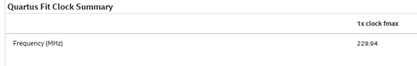
Figure 27.
With the HDL coder, things are a little more complicated.
In order not to inflate the article, I will not provide an m-script for this task, it should not cause difficulties. The m-script written in the forehead can hardly be successfully used, but if you edit the code and correctly specify the places for pipelining, we get a working result. This, of course, will take several tens of minutes, but not hours.
In C ++, it is also desirable to set the directives and translate the calculations to a fixed point, which will also take a very little time.
So, using high-level development tools, we save time, and the more complex the algorithm, the more time it saves - this will continue until we run into FPGA resource limits or strict computational speed limits where you have to tackle HDL.
What can be said in conclusion.
Obviously, the golden hammer has not yet been invented, but there are additional tools that can be used in development.
The main advantage of high-level tools, in my opinion, is the speed of development. It’s a reality to get enough quality in terms of time, sometimes an order of magnitude smaller than when developing using HDL.
To such advantages as using legacy code for FPGA and connecting programmers to FPGA development without preliminary preparation, I am wary. To get satisfactory results, you will have to abandon many familiar programming techniques.
Once again, I want to note that this article is just a superficial look at the high-level development tools for FPGA.
The HLS compiler has great opportunities for optimizations: pragmas, special libraries with optimized functions, interface descriptions, a lot of articles on the Internet about “best practices”, etc. The MATLAB chip, which has not been considered, is the ability to directly generate, for example, a filter from the GUI without writing a single line of code, simply indicating the desired characteristics, which further accelerates development time.
Who won today's study? My opinion is the Intel HLS compiler. It generates a working design even from non-optimized code. HDL coder without thoughtful analysis and code processing I would be afraid to use. I also want to note that HDL coder is quite an old tool, but as I know, it has not gained wide recognition. But HLS, although young, it can be seen that FPGA manufacturers are betting on it, I think we will see its further development and growth in popularity.
Xilinx representatives assure that the development and implementation of high-level tools is the only opportunity in the future to develop for larger and larger FPGA chips. Traditional tools simply will not be able to cope with this, and Verilog / VHDL is probably destined for assembler, but this is in the future. And now we have in our hands development tools (with its pros and cons), which we must choose based on the task.
Will I use high-level development tools in my work? Rather, yes, now their development is going by leaps and bounds, so we must at least keep up, but I see no objective reasons to immediately abandon HDL.
In the end, I want to note once again that at this stage of the development of high-level design tools, the user should not forget for a minute that he writes a program that is not executable in the processor, but creates a circuit with real wires, triggers and logic elements.
As an FPGA developer, I use Verilog's hardware description language ( HDL ) as the main tool , but the growing popularity of new methods aroused my great interest, so in this article I decided to make out what was happening.
This article is not a guide or instruction for use, this is my review and conclusions about what various high-level development tools can give to an FPGA developer or programmer who wants to plunge into the world of FPGA. In order to compare the most interesting development tools in my opinion, I wrote several tests and analyzed the results. Under the cut - what came of it.
Why do you need high-level development tools for FPGA?
- To accelerate the development of the project
- by reusing the code already written in high-level languages;
- through the use of all the advantages of high-level languages, when writing code from scratch;
- by reducing compilation time and code verification. - Ability to create universal code that will work on any FPGA family.
- Reduce the development threshold for FPGAs, for example, avoiding the concepts of “clock frequency” and other low-level entities. Ability to write code for FPGA to a developer not familiar with HDL.
Where do high-level development tools come from?
Now many are attracted by the idea of high-level development. Both enthusiasts, such as, for example, Quokka and the Python code generator , and corporations, such as Mathworks , and FPGA manufacturers Intel and Xilinx,
each use their own methods and tools to achieve this. Enthusiasts in the struggle for a perfect and beautiful world use their favorite development languages, such as Python or C #. Corporations, trying to please the client, offer their own or adapt existing tools. Mathworks offers its own HDL coder tool for generating HDL code from m-scripts and Simulink models, while Intel and Xilinx offer compilers for common C / C ++.
At the moment, companies with significant financial and human resources have achieved greater success, while enthusiasts are somewhat behind. This article will be devoted to the consideration of the product HDL coder from Mathworks and HLS Compiler from Intel.
What about Xilinx
In this article, I do not consider HIL from Xilinx, due to the different architectures and CAD systems of Intel and Xilinx, which makes it impossible to make an unambiguous comparison of the results. But I want to note that Xilinx HLS, like Intel HLS, provides a C / C ++ compiler and they are conceptually similar.
Let's start comparing HDL coder from Mathworks and Intel HLS Compiler, having solved several problems using different approaches.
Comparison of high-level development tools
Test one. “Two multipliers and an adder”
The solution to this problem has no practical value, but is well suited as a first test. The function takes 4 parameters, multiplies the first with the second, the third with the fourth and adds the results of the multiplication. Nothing complicated, but let's see how our subjects cope with this.
HDL coder by Mathworks
To solve this problem, the m-script looks as follows:
function [out] = TwoMultAdd(a,b,c,d)
    out = (a*b)+(c*d);
end
Let's see what Mathworks offers us to convert code to HDL.
I will not examine in detail the work with HDL-coder, I will focus only on those settings that I will change in the future to get different results in FPGA, and the changes of which will have to be considered by a MATLAB programmer who needs to run his code in FPGA.
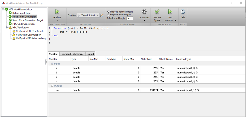
So, the first thing to do is set the type and range of input values. There are no familiar char, int, float, double in FPGA. The bit depth of the number can be any, it is logical to choose it based on the range of input values that you plan to use.
Picture 1
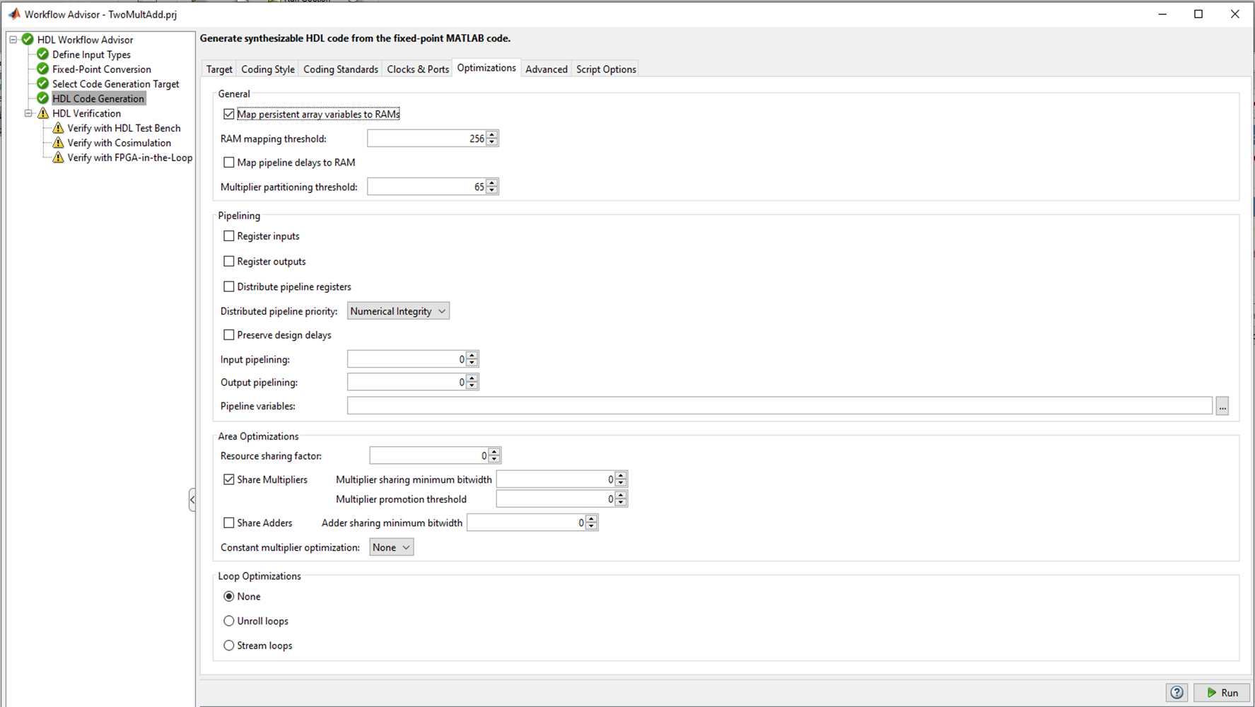
MATLAB checks the types of variables, their values and selects the correct bit depths for buses and registers, which is really convenient. If there are no problems with bit depth and typing, you can proceed to the following points. Figure 2 There are several tabs in the HDL Code Generation where you can choose the language to convert to (Verilog or VHDL); code style names of signals. The most interesting tab, in my opinion, is Optimization, and I will experiment with it, but later, for now, let's leave all the defaults and see what happens with the HDL coder “out of the box”. Press the Run button and get the following code:
`timescale 1 ns / 1 ns
module TwoMultAdd_fixpt
          (a,
           b,
           c,
           d,
           out);
  input   [7:0] a;  // ufix8
  input   [7:0] b;  // ufix8
  input   [7:0] c;  // ufix8
  input   [7:0] d;  // ufix8
  output  [16:0] out;  // ufix17
  wire [15:0] TwoMultAdd_fixpt_mul_temp;  // ufix16
  wire [16:0] TwoMultAdd_fixpt_2;  // ufix17
  wire [15:0] TwoMultAdd_fixpt_mul_temp_1;  // ufix16
  wire [16:0] TwoMultAdd_fixpt_3;  // ufix17
  //HDL code generation from MATLAB function: TwoMultAdd_fixpt
  //%%%%%%%%%%%%%%%%%%%%%%%%%%%%%%%%%%%%%%%%%%%%%%%%%%%%%%%%%%%%%%%%%%%%%%%%%%%
  //                                                                          %
  //           Generated by MATLAB 9.2 and Fixed-Point Designer 5.4           %
  //                                                                          %
  //%%%%%%%%%%%%%%%%%%%%%%%%%%%%%%%%%%%%%%%%%%%%%%%%%%%%%%%%%%%%%%%%%%%%%%%%%%%
  assign TwoMultAdd_fixpt_mul_temp = a * b;
  assign TwoMultAdd_fixpt_2 = {1'b0, TwoMultAdd_fixpt_mul_temp};
  assign TwoMultAdd_fixpt_mul_temp_1 = c * d;
  assign TwoMultAdd_fixpt_3 = {1'b0, TwoMultAdd_fixpt_mul_temp_1};
  assign out = TwoMultAdd_fixpt_2 + TwoMultAdd_fixpt_3;
endmodule  // TwoMultAdd_fixpt
The code looks good. MATLAB understands that writing the entire expression on a single line on Verilog is bad practice. Creates separate wires for the multiplier and adder, there’s nothing to complain about.
It is alarming that the description of the registers is missing. This happened because we did not ask HDL-coder about this, and left all the fields in the settings to their default values.
Here is what Quartus synthesizes from such code.
Figure 3
No problems, everything was as planned.
In FPGA we implement synchronous circuits, and still I would like to see the registers. HDL-coder offers a mechanism for placing registers, but where to place them is up to the developer. We can place the registers at the input of the multipliers, at the output of the multipliers in front of the adder, or at the output of the adder.
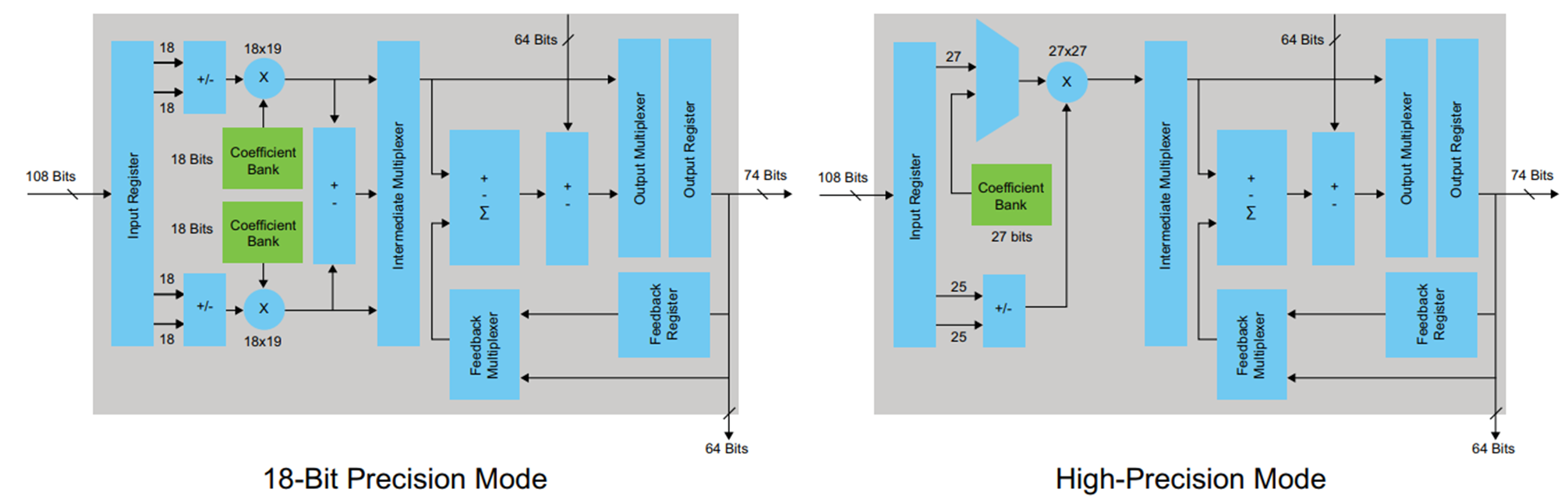
To synthesize the examples, I chose the FPGA Cyclone V family, where special DSP blocks with built-in adders and multipliers are used to implement arithmetic operations. The DSP block looks like this: Figure 4
DSP block has input and output registers. There is no need to try to snap the results of multiplication in the register before addition, this will only violate the architecture (in certain cases, this option is possible and even needed). It is up to the developer to decide how to deal with the input and output register based on the latency requirements and the required maximum frequency. I decided to use only the output register. In order for this register to be described in the code generated by the HDL-coder, in the Options tab in the HDL coder you need to check the Register output checkbox and restart the conversion.
It turns out the following code:
`timescale 1 ns / 1 ns
module TwoMultAdd_fixpt
          (clk,
           reset,
           clke_ena_i,
           a,
           b,
           c,
           d,
           clke_ena_o,
           out);
  input   clk;
  input   reset;
  input   clke_ena_i;
  input   [7:0] a;  // ufix8
  input   [7:0] b;  // ufix8
  input   [7:0] c;  // ufix8
  input   [7:0] d;  // ufix8
  output  clke_ena_o;
  output  [16:0] out;  // ufix17
  wire enb;
  wire [16:0] out_1;  // ufix17
  wire [15:0] TwoMultAdd_fixpt_mul_temp;  // ufix16
  wire [16:0] TwoMultAdd_fixpt_2;  // ufix17
  wire [15:0] TwoMultAdd_fixpt_mul_temp_1;  // ufix16
  wire [16:0] TwoMultAdd_fixpt_3;  // ufix17
  reg [16:0] out_2;  // ufix17
  //HDL code generation from MATLAB function: TwoMultAdd_fixpt
  //%%%%%%%%%%%%%%%%%%%%%%%%%%%%%%%%%%%%%%%%%%%%%%%%%%%%%%%%%%%%%%%%%%%%%%%%%%%
  //                                                                          %
  //           Generated by MATLAB 9.2 and Fixed-Point Designer 5.4           %
  //                                                                          %
  //%%%%%%%%%%%%%%%%%%%%%%%%%%%%%%%%%%%%%%%%%%%%%%%%%%%%%%%%%%%%%%%%%%%%%%%%%%%
  assign TwoMultAdd_fixpt_mul_temp = a * b;
  assign TwoMultAdd_fixpt_2 = {1'b0, TwoMultAdd_fixpt_mul_temp};
  assign TwoMultAdd_fixpt_mul_temp_1 = c * d;
  assign TwoMultAdd_fixpt_3 = {1'b0, TwoMultAdd_fixpt_mul_temp_1};
  assign out_1 = TwoMultAdd_fixpt_2 + TwoMultAdd_fixpt_3;
  assign enb = clke_ena_i;
  always @(posedge clk or posedge reset)
    begin : out_reg_process
      if (reset == 1'b1) begin
        out_2 <= 17'b00000000000000000;
      end
      else begin
        if (enb) begin
          out_2 <= out_1;
        end
      end
    end
  assign clke_ena_o = clke_ena_i;
  assign out = out_2;
endmodule  // TwoMultAdd_fixpt
As you can see, the code has fundamental differences compared to the previous version. An always-block appeared, which is a description of the register (just what we wanted). For the always-block operation, the inputs of the clk module (clock frequency) and reset (reset) also appeared. It can be seen that the output of the adder is latched in the trigger described in always. There are also a couple of ena permission signals, but they are not very interesting to us.
Let's look at the diagram that Quartus now synthesizes.
Figure 5
Again, the results are good and expected.
The table below shows the table of used resources - we keep it in mind.
Figure 6
For this first assignment, Mathworks receives a credit. Everything is not complicated, predictable and with the desired result.
I described in detail a simple example, provided a diagram of a DSP block and described the possibilities of using the register usage settings in HDL-coder, which are different from the “default” settings. This is done for a reason. By this, I wanted to emphasize that even in such a simple example, when using HDL-coder, knowledge of the FPGA architecture and the fundamentals of digital circuitry is necessary, and the settings must be changed consciously.
Intel HLS Compiler
Let's try to compile code with the same functionality written in C ++ and see what is eventually synthesized in FPGA using the HLS compiler.
So C ++ code
component unsigned int TwoMultAdd(unsigned char a, unsigned char b, unsigned char c, unsigned char d)
{
	return (a*b)+(c*d);
}
I selected data types to avoid overflowing variables.
There are advanced methods for setting bit depths, but our goal is to test the ability to assemble functions written in C / C ++ style under FPGA without making any changes, all out of the box.
Since the HLS compiler is a native tool of Intel, we collect the code with a special compiler and check the result immediately in Quartus.
Let's look at the circuit that Quartus synthesizes.
Figure 7
The compiler created the input and output registers, but the essence is hidden in the wrapper module. We begin to deploy the wrapper and ... see more, more and more nested modules.
The structure of the project looks like this. Figure 8 An obvious hint from Intel: “don't get your hands on it!”. But we will try, especially the functionality is not complicated.
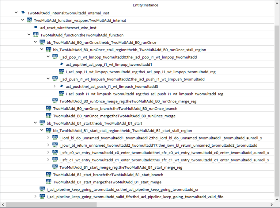
In the depths of the Project Tree | quartus_compile | TwoMultAdd: TwoMultAdd_inst | TwoMultAdd_internal: twomultadd_internal_inst | TwoMultAdd_fu
nction_wrapper: TwoMultAdd_internal | TwoMultAdd_function: theTwoMultAdd_function | bb_TwoMultAdd_B1_start:
thebb_TwoMultAdd_B1_start | bb_TwoMultAdd_B1_start_stall_region: thebb_TwoMultAdd_B1_start_stall_region | i
_sfc_c1_wt_entry_twomultadd_c1_enter_twomultadd: thei_sfc_c1_wt_entry_twomultadd_c1_enter_twomultad
d_aunroll_x | i_sfc_logic_c1_wt_entry_twomultadd_c1_enter_twomultadd13: thei_sfc_logic_c1_wt_entry_twom
ultadd_c1_enter_twomultadd13_aunroll_x | mult1 is desired module.
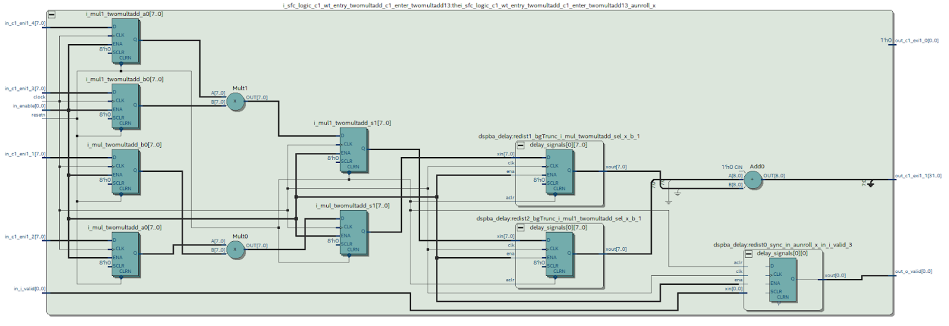
We can look at the diagram of the desired module synthesized by Quartus. Figure 9 What conclusions can be drawn from this scheme.
It can be seen that something happened that we tried to avoid when working in MATLAB: the case at the output of the multiplier was synthesized - this is not very good. It can be seen from the DSP block diagram (Figure 4) that there is only one register at its output, which means that each multiplication will have to be done in a separate block.
The table of used resources shows what this leads to.
Figure 10
Compare the results with the HDL coder table (Figure 6).
If using a larger number of registers you can put up with, then spending precious DSP blocks on such a simple functionality is very unpleasant.
But there is a huge plus in Intel HLS compared to HDL coder. With the default settings, the HLS compiler developed a synchronous design in FPGA, although it expended more resources. Such an architecture is possible, it is clear that Intel HLS is configured to achieve maximum performance, and not to save resources.
Let's see how our subjects behave with more complex projects.
The second test. “Element-wise multiplication of matrices with summation of the result”
This function is widely used in image processing: the so-called “matrix filter” . We sell it using high-level tools.
HDL coder by Mathwork
Work immediately begins with a limitation. HDL Coder cannot accept 2-D matrix functions as inputs. Considering that MATLAB is a tool for working with matrices, this is a serious blow to the entire inherited code, which can become a serious problem. If the code is written from scratch, this is an unpleasant feature that must be considered. So you have to deploy all the matrices into a vector and implement the functions taking into account the input vectors.
The code for the function in MATLAB is as follows
function [out] = mhls_conv2_manually(target,kernel)
    len = length(kernel);
    mult = target.*kernel;
    summ = sum(mult);
    out = summ/len;
end
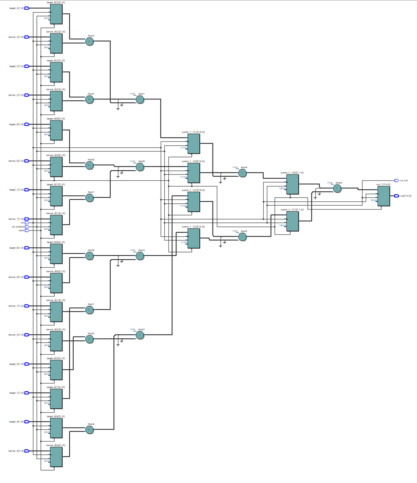
The generated HDL code turned out to be very bloated and contains hundreds of lines, so I will not give it here. Let's see what scheme Quartus synthesizes from this code. Figure 11 This circuit looks unsuccessful. Formally, it is working, but I assume that it will work at a very low frequency, and it can hardly be used in real hardware. But any assumption must be verified. To do this, we will place the registers at the input and output of this circuit and with the help of Timing Analyzer we will evaluate the real situation. To conduct the analysis, you must specify the desired operating frequency of the circuit so that Quartus knows what to strive for when wiring, and in case of failure, provides reports of violations. We set the frequency to 100 MHz, let's see what Quartus can squeeze out of the proposed circuit.
Figure 12
It can be seen that it turned out a little: 33 MHz look frivolous. The delay in the chain of multipliers and adders is about 30 ns. To get rid of this “bottleneck”, you need to use the conveyor: insert registers after arithmetic operations, thereby reducing the critical path.
HDL coder gives us this opportunity. In the Options tab, you can set Pipeline variables. Since the code in question is written in the MATLAB style, there is no way to pipe variables (except mult and summ variables), which does not suit us. It is necessary to insert the registers into the intermediate circuits hidden in our HDL code.
Moreover, the situation with optimization could be worse. For example, nothing prevents us from writing code
out = (sum(target.*kernel))/len;it is quite adequate for MATLAB, but completely deprives us of the possibility of optimizing HDL.
The next way out is to edit the code by hand. This is a very important point, as we refuse to inherit and begin to rewrite the m-script, and NOT in the MATLAB style.
The new code is as follows
function [out] = mhls_conv2_manually(target,kernel)
    len = length(kernel);
    mult = target.*kernel;
    summ_1 = zeros([1,(len/2)]);
    summ_2 = zeros([1,(len/4)]);
    summ_3 = zeros([1,(len/8)]);
    for i=0:1:(len/2)-1
        summ_1(i+1) = (mult(i*2+1)+mult(i*2+2));
    end
    for i=0:1:(len/4)-1
        summ_2(i+1) = (summ_1(i*2+1)+summ_1(i*2+2));
    end
    for i=0:1:(len/8)-1
        summ_3(i+1) = (summ_2(i*2+1)+summ_2(i*2+2));
    end
    out = summ_3/len;
end
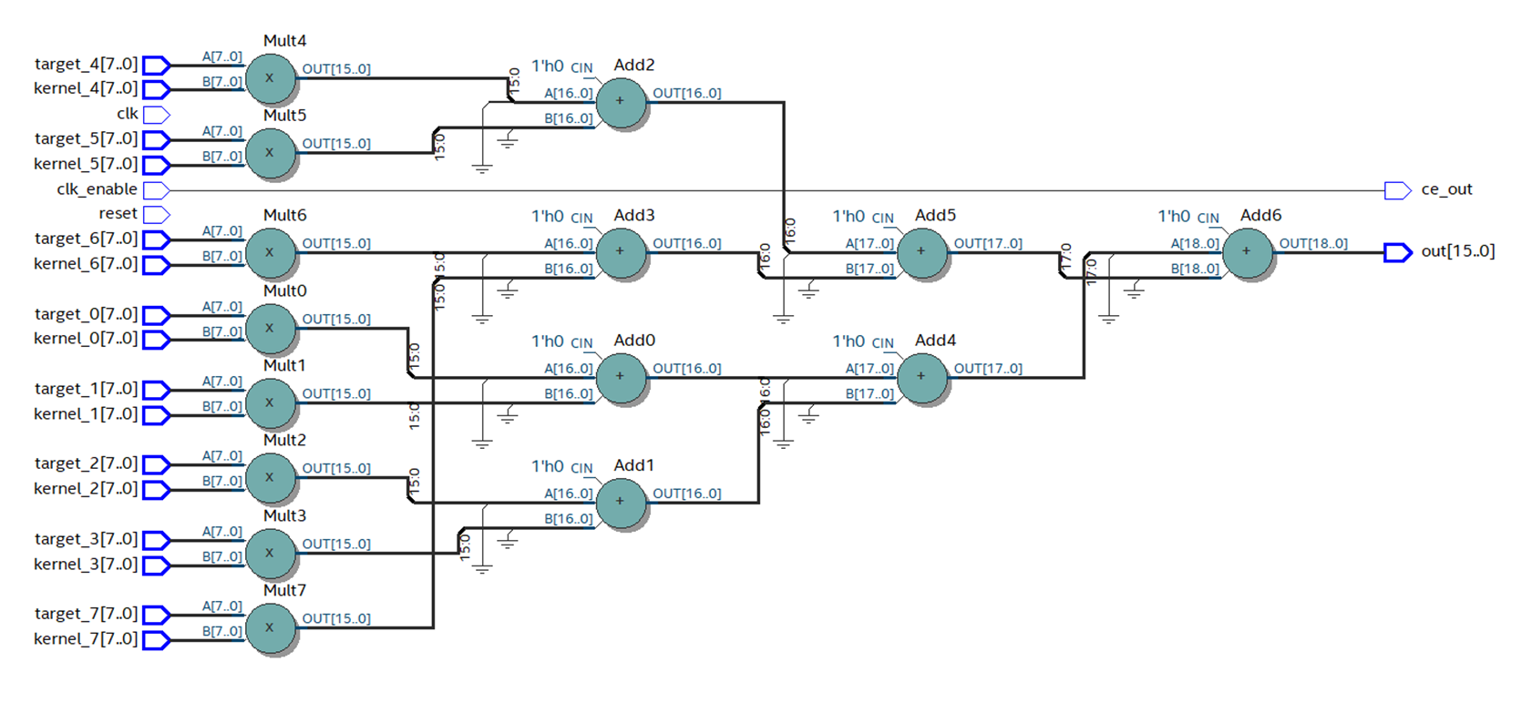
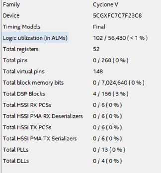
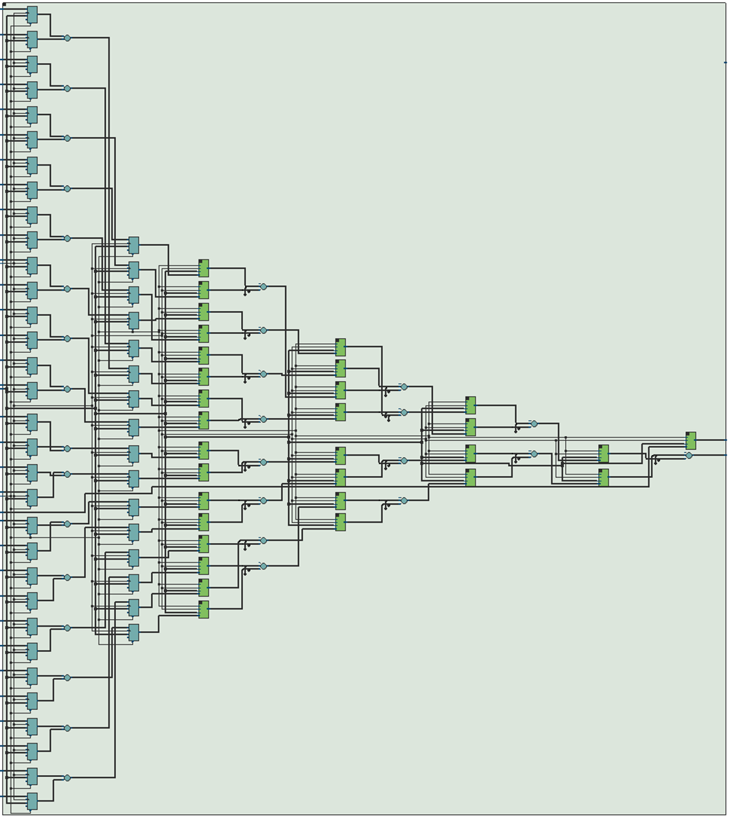
In Quartus, we collect the code generated by the HDL Coder. It can be seen that the number of layers with primitives has decreased, and the scheme looks much better. Figure 12 With the correct arrangement of primitives, the frequency increases almost 3 times, up to 88 MHz. Figure 13 Now the final touch: in the Optimization settings, specify summ_1, summ_2 and summ_3 as elements of the pipeline. We collect the resulting code in Quartus. The scheme changes as follows: Figure 14 The maximum frequency increases again and now its value is about 195 MHz. Figure 15 How many resources on the chip will take such a design? Figure 16 shows the table of used resources for the described case. Figure 16
What conclusions can be drawn after considering this example?
The main disadvantage of HDL coder is that it is unlikely to use MATLAB code in its pure form.
There is no support for matrices as function inputs, the layout of the code in the MATLAB style is mediocre.
The main danger is the lack of registers in the code generated without additional settings. Without these registers, even having received formally working HDL code without syntax errors, the use of such code in modern realities and developments is undesirable.
It is advisable to immediately write code sharpened for conversion to HDL. In this case, you can get quite acceptable results in terms of speed and resource intensity.
If you are a MATLAB developer, do not rush to click the Run button and compile your code under FPGA, remember that your code will be synthesized into a real circuit. =)
Intel HLS Compiler
For the same functionality, I wrote the following C / C ++ code
component unsigned int conv(unsigned char *data, unsigned char *kernel)
{
    unsigned int mult_res[16];
    unsigned int summl;
	summl = 0;
	for (int i = 0; i < 16; i++)
	{
		mult_res[i] = data[i] * kernel[i];
		summl = summl+mult_res[i];
	}
	return summl/16;
}
The first thing that catches your eye is the amount of resources used.
Figure 17
It can be seen from the table that only 1 DSP block was used, so something went wrong, and multiplications are not performed in parallel. The number of registers used is also surprising, and even memory is involved, but this is left to the conscience of the HLS compiler.
It is worth noting that the HLS compiler has developed a sub-optimal, using a huge amount of extra resources, but still a working circuit that, according to Quartus reports, will work at an acceptable frequency, and such a failure as the HDL coder will not.
Figure 18
Let's try to improve the situation. What is needed for this? That's right, close your eyes to inheritance and crawl into the code, but so far it’s not much.
HLS has special directives for optimizing code for FPGA. We insert the unroll directive, which should expand our loop in parallel:
#pragma unroll
	for (int i = 0; i < 16; i++)
	{
		mult_res[i] = data[i] * kernel[i];
	}
Let's see how Quartus reacted to this.
Figure 19
First of all, we pay attention to the number of DSP blocks - there are 16 of them, which means multiplications are performed in parallel.
Hurrah! unroll works! But it’s already hard to put up with how much the utilization of other resources has grown. The circuit has become completely unreadable. Figure 20 I believe this was due to the fact that no one pointed out to the compiler that calculations in fixed-point numbers are quite suitable for us, and he honestly implemented all floating-point math on logic and registers. We need to explain to the compiler what is required of it, and for this we again plunge into the code. For the purpose of using fixed-point, template classes are implemented. Figure 21

Speaking in our own words, we can use variables whose bit depth is set manually up to a bit. For those who write in HDL, you can’t get used to it, but C / C ++ programmers will probably clutch their heads. Bit depths, as in MATLAB, in this case no one will tell, and the developer himself must count the number of bits.
Let's see how it looks in practice.
We edit the code as follows:
component ac_fixed<16,16,false> conv(ac_fixed<8,8,false> *data, ac_fixed<8,8,false> *kernel)
{
	ac_fixed<16,16,false>mult_res[16];
    ac_fixed<32,32,false>summl;
	#pragma unroll
	for (int i = 0; i < 16; i++)
	{
		mult_res[i] = data[i] * kernel[i];
	}
	for (int i = 0; i < 16; i++)
	{
		summl = summl+mult_res[i];
	}
	return summl/16;
}
And instead of the creepy pasta from Figure 20, we get this beauty: Figure 22 Unfortunately, something strange continues to happen with the resources used. Figure 23 But a detailed examination of the reports shows that the module that interests us directly looks more than adequate: Figure 24 The huge consumption of registers and block memory is associated with a large number of peripheral modules. I still do not fully understand the deep meaning of their existence, and this will need to be dealt with, but the problem is solved. In an extreme case, you can carefully cut out one module of interest to us from the general structure of the project, which will save us from peripheral modules that devour resources.

The third test. “Transition from RGB to HSV”
Starting to write this article, I did not expect it to be so voluminous. But I can’t refuse the third and the last in the framework of this article, an example.
Firstly, this is a real-life example from my practice, and it was because of it that I began to look towards high-level development tools.
Secondly, from the first two examples, we could make the assumption that the more complex the design, the worse the high-level tools cope with the task.
I want to demonstrate that this judgment is erroneous, and in fact, the more complex the task, the more the advantages of high-level development tools are manifested.
Last year, when working on one of the projects, I did not like the camera purchased on Aliexpress, namely, the colors were not saturated enough. One of the popular ways to vary the color saturation is to switch from the RGB color space to the HSV space, where one of the parameters is the saturation. I remember how I opened the transition formula and took a deep breath ... Implementing such calculations in FPGA is not something extraordinary, but of course it will take time to write code. So, the formula for switching from RGB to HSV is as follows:
Figure 25
Implementation of such an algorithm in FPGA will take not days, but hours, and all this must be done very carefully due to the specifics of HDL, and implementation in C ++ or in MATLAB will take, I think, minutes .
In C ++, you can write code directly in the forehead and still get a working result.
I wrote the following option in C ++
struct color_space{
	unsigned char rh;
	unsigned char gs;
	unsigned char bv;
};
component color_space rgb2hsv(color_space rgb_0)
{
	color_space hsv;
	float h,s,v,r,g,b;
	float max_col, min_col;
	r = static_cast(rgb_0.rh)/255;
	g = static_cast(rgb_0.gs)/255;
	b = static_cast(rgb_0.bv)/255;
	max_col = std::max(std::max(r,g),b);
	min_col = std::min(std::min(r,g),b);
	//расчет H
	if (max_col == min_col)
		h = 0;
	else if (max_col==r && g>=b)
		h = 60*((g-b)/(max_col-min_col));
	else if (max_col==r && g(h);
	hsv.gs = static_cast(s);
	hsv.bv = static_cast(v);
	return hsv;
}
And Quartus successfully implemented the result, as can be seen from the table of used resources.
Figure 26.
The frequency is very good.
Figure 27.
With the HDL coder, things are a little more complicated.
In order not to inflate the article, I will not provide an m-script for this task, it should not cause difficulties. The m-script written in the forehead can hardly be successfully used, but if you edit the code and correctly specify the places for pipelining, we get a working result. This, of course, will take several tens of minutes, but not hours.
In C ++, it is also desirable to set the directives and translate the calculations to a fixed point, which will also take a very little time.
So, using high-level development tools, we save time, and the more complex the algorithm, the more time it saves - this will continue until we run into FPGA resource limits or strict computational speed limits where you have to tackle HDL.
Conclusion
What can be said in conclusion.
Obviously, the golden hammer has not yet been invented, but there are additional tools that can be used in development.
The main advantage of high-level tools, in my opinion, is the speed of development. It’s a reality to get enough quality in terms of time, sometimes an order of magnitude smaller than when developing using HDL.
To such advantages as using legacy code for FPGA and connecting programmers to FPGA development without preliminary preparation, I am wary. To get satisfactory results, you will have to abandon many familiar programming techniques.
Once again, I want to note that this article is just a superficial look at the high-level development tools for FPGA.
The HLS compiler has great opportunities for optimizations: pragmas, special libraries with optimized functions, interface descriptions, a lot of articles on the Internet about “best practices”, etc. The MATLAB chip, which has not been considered, is the ability to directly generate, for example, a filter from the GUI without writing a single line of code, simply indicating the desired characteristics, which further accelerates development time.
Who won today's study? My opinion is the Intel HLS compiler. It generates a working design even from non-optimized code. HDL coder without thoughtful analysis and code processing I would be afraid to use. I also want to note that HDL coder is quite an old tool, but as I know, it has not gained wide recognition. But HLS, although young, it can be seen that FPGA manufacturers are betting on it, I think we will see its further development and growth in popularity.
Xilinx representatives assure that the development and implementation of high-level tools is the only opportunity in the future to develop for larger and larger FPGA chips. Traditional tools simply will not be able to cope with this, and Verilog / VHDL is probably destined for assembler, but this is in the future. And now we have in our hands development tools (with its pros and cons), which we must choose based on the task.
Will I use high-level development tools in my work? Rather, yes, now their development is going by leaps and bounds, so we must at least keep up, but I see no objective reasons to immediately abandon HDL.
In the end, I want to note once again that at this stage of the development of high-level design tools, the user should not forget for a minute that he writes a program that is not executable in the processor, but creates a circuit with real wires, triggers and logic elements.