Making a simple sonar modem
- Tutorial
Hello dear!
In this article, by popular demand, we will tell you how to make a simple hydroacoustic modem: a bit of digital signal processing, a bit of programming, a little home-made printed circuit boards and a drop of practical hydrology.
To all those who are interested - we ask you to be welcome under the cut, to the reverberating world of underwater communication!
And here is the relevant picture, to attract attention:
“Ultimately, the meaning of our existence is to spend energy ... And if possible, you know, so that it’s interesting to yourself, and to others is useful.”
(C) ABS, Midday, XXII Century
Save Your Time - Summary
- Acoustic modems are not yet sold on Aliexpress
- There is a simple and undemanding to computing resources tone detection method, the frequency of which is 4 times less than the sampling frequency; Arduino is enough for implementation
- Sample code for PC lies on GitHub
- We make receiving and transmitting antennas from pie pickers of 10 r each
- We buy (or do it ourselves) an amplifier board on TDA2030 on Ali for 50 rubles
- We make a LUT-ohm preamplifier, with a total cost of ~ 100 rubles
- We connect and go to the pond
- Rejoice
Motivational Prelude
Now you can buy almost anything on Aliexpress or eBay. Especially a lot of different things for the independent manufacture of something electronic based on Arduino. You can make (if you just don’t buy it interesting) a milieu-stopover weather station with an Internet connection, an automatic cat feeder, a home brewery controller, but you still cannot buy a sonar modem, a designer for its manufacture, or at least a module for adruino. Well and good! And do not - now we will tell you how to make it, and also tell how it works.
We the whole laboratory for a long time thought what can be offered to lovers for independent manufacture. Something very simple, which can be collected by a schoolboy, from a
Something promising a long and exciting improvement, something that can later be transferred even to arduino
If we approach the issue materialistically, we would like to offer a detailed tutorial for the manufacture of a simple device that would be more or less able to transmit data in a shallow water body (a shallow sonar channel is the most complex), which would mean maximum production of a printed circuit board using LUT, with a total cost not exceeding a couple of three hundred rubles at minimal points.
What will we do today?
- remember how to make a suitable sonar antenna and make a couple;
- connect one of the antennas to a PC through an amplifier on the TDA for ~ 50 rubles and get a transmitter;
- for the second, we’ll make a preamplifier using ~ LUT for ~ 100 rubles;
- we
’llwrite(I already wrote everything and put it on Git) asimple modem in C # and try everything in the nearest body of water;
What do we need for this?
- two piezoelectric elements. For example, from a clock or postcard ;
- RG-174 / U cable (or similar) ~ 5 meters;
- acetic sealant;
- water resistant varnish;
- foil textolite, a total of approximately 100x200 mm;
- an amplifier for TDA2030 (for example, one for 50 rubles);
- preamp components
How does it work?
The whole idea of the simplest modem is built on, again, the simplest (coincidence?) Detector of a certain tone, about which, to my shame, I have not heard. Told me about him completely by chance andrey_9999a . By the way, he also made a preamplifier board.
In this regard, I recalled a quote from Leonard Sasskind's book “The Battle of the Black Hole”:
“As a wine connoisseur, I am more or less sure that even with my eyes closed I can distinguish red from white. Even more reliably, I distinguish wine from beer. But then taste will let me down. ”I can say to myself that as a real electronics engineer I’m more or less sure that I can definitely solder two thick wires. Even more reliably, I distinguish a hot soldering iron from a cold one even with my eyes closed, but then the skill will let me down. Therefore, everything related to the development and manufacture of boards is the work of my comrades and colleagues andrey_9999a and StDmitriev .
So, back to the detector. It is a simplified particular case of computing the Fourier integral:

In the case of a digital signal, to calculate the amplitude of an arbitrary harmonic, it will be necessary to perform a discrete Fourier transform, for Arduina this is difficult, but the trick is that if you take Fc as the carrier frequency such that it will be exactly 4 times less than the sampling frequency Fs , then the amplitude of this harmonic can be calculated demonically easier.
In this case, dt = 2π * (Fs / 4) / Fs = π / 2 , and there are only 4 samples per carrier period:

If everything is shifted to π / 4, then the samples will take only two values: √2 / 2 and -√ 2/2, for simplicity we’ll leave only the signs “+” and “-” .
The essence of the method is that we represent the sinus phase as a sequence of signs"+" "+" "-" "-" , and the cosine as "+" "-" "-" "+" .
Let the input signal lies in the buffer sn , we have two annular homogenization buffer sine and cosine phases - bs and bc size N . Pointers to the head and tail are common for them - bH and bT . At the initial moment of time, bH = N-1, bT = 0 . Averaging cycle counter C = 0 .
We take 4 samples from the input buffer and add them according to the sequences of characters.
Code example
a = sn(i)

bs(bH) = a

bc(bH) = a

s1 = s1 + a - bs(bT)

s2 = s2 + a - bc(bT)

bH = (bH + 1) % N

bT = (bT + 1) % N


a = sn(i+1)

bs(bH) = a

bc(bH) = -a

s1 = s1 + a - bs(bT)

s2 = s2 - a - bc(bT)

bH = (bH + 1) % N

bT = (bT + 1) % N


a = sn(i+2)

bs(bH) = -a

bc(bH) = -a

s1 = s1 - a - bs(bT)

s2 = s2 - a - bc(bT)

bH = (bH + 1) % N

bT = (bT + 1) % N


a = sn(i+3)

bs(bH) = -a

bc(bH) = a

s1 = s1 - a - bs(bT)

s2 = s2 + a - bc(bT)

bH = (bH + 1) % N

bT = (bT + 1) % N
After each processed four samples, we check the counter of averaging cycles and if it has exceeded N , then we calculate the carrier amplitude cA :
if ++cycle >= N
      cA = sqrt(s1 * s1 + s2 * s2)
      cycle = 0
end
This is how it looks on an ideal signal: The signal
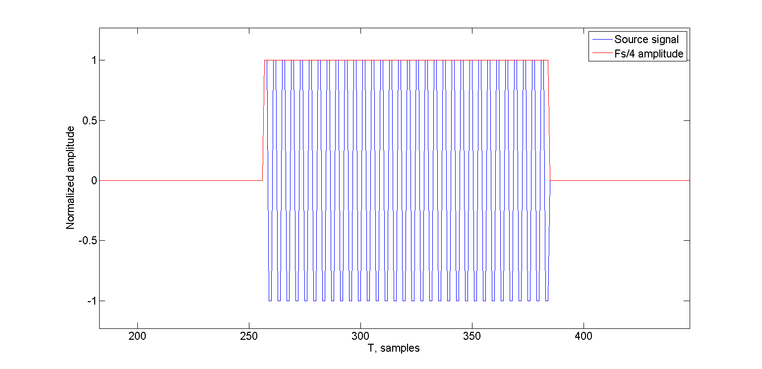
itself is shown in blue, the carrier amplitude values in red (everything is reduced to the range -1..1). In this case, N = 2 since there is no noise and everything works fine anyway.
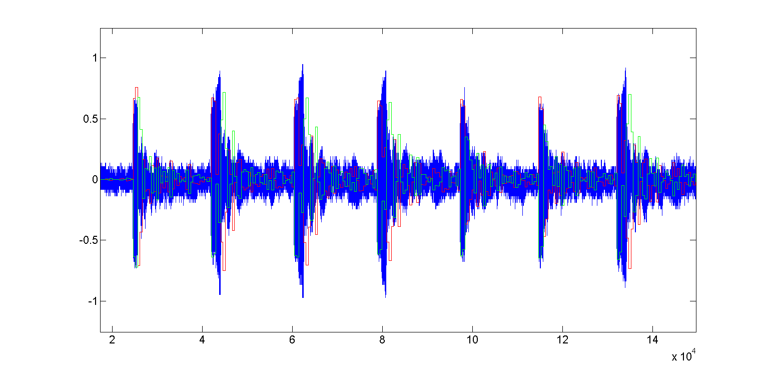
Now add some white noise and see how our detector reacts to it:

I added white noise so that the signal-to-noise ratio is 0 dB. In the figure above, the noisy signal is shown in blue, the source signal in green, and the amplitude value in red. In this case, the detector at N = 2 already did not detect anything, and the minimum N at which it works properly is 32. That is, the size of the processing window in samples was 32 * 4 = 128 samples.
That is, now we can analyze the input signal and evaluate a parameter that quantifies the presence of a frequency, four times less than the sampling frequency. If you set a certain threshold value for this parameter, then everything can be binarized, and speaking in a simple way, we can answer the question: is there a given tone in the input signal or not?
This is very good, but we need to transmit bits, and bits can take two values.
Implementing a system with two signaling states with the help of one is an idea so-so, therefore we will not encode one of the states with silence (pause). This would make detection very difficult: it would be necessary to somehow highlight the beginning of the premise, figure out how to arrange its end, etc.
Instead, “1” and “0” we will encode with pulses of different lengths, between the bits there is a so-called guard interval - because we still need to deal with multipath propagation and reverb. In simple terms, the guard interval is the place (time) where all reflections of the previous bit, all after-sounds and echoes die out.
Looking ahead, we note that with such a signal structure, the receiver’s operation algorithm is greatly simplified: we wait for the tone to appear, notice the beginning, wait for the tone to disappear and again note the time - if the received time is more like “1” in length, probably we took a bit with a value of “1”, if it looks more like “0” - then apparently we took a bit with a value of “0”.
In general, we can say that this is some kind of morse code.
Software part of the modem
For the impatient - an example lies on GitHub . It was whipped up in C # (because for the PC I write on it and it’s just more convenient and faster for me).
The wonderful NAudio library is used to play and capture sound from the microphone input .
All modem logic is in the SUAModem (Simple Underwater Acoustic Modem) class .
The following parameters are transferred to the constructor:
double sRateHz - sampling frequency in Hertz;
int wSize - the size of the processing window in samples;
int oneMultiplier - how many "windows" lasts a bit with a value of "1"
int zeroMultiplier - how many "windows" lasts a bit with a value of "
double " double eThreshold - a threshold, let's talk about it later
To generate a signal from an array of bytes, there is a ModulateData (byte [] data) method, which returns an array of 16-bit signed samples.
public short [] ModulateData (byte [] data)
public short[] ModulateData(byte[] data)
{
   double alpha = 0;
   double phase = 0;
   List samples = new List();
   BitArray bits = new BitArray(data);
   for (int i = 0; i < bits.Length; i++)
   {
         int sLim = (bits[i]) ? oneDurationSmp : zeroDurationSmp;
         alpha = 0;
         phase = 0;
         for (int sIdx = 0; sIdx <= sLim; sIdx++)
         {
               alpha = Math.Sin(phase);
               phase += delta;
               if (phase >= alimit)
                        phase -= alimit;
               samples.Add(Convert.ToInt16(alpha * short.MaxValue));
         }
         samples.AddRange(new short[defenseIntervalSmp]);
     }
     return samples.ToArray();
}
In the main loop by transmitted bits, the samples list is populated. Depending on the current transmitted bit, the length sLim of the generated signal in samples is set. A guard interval is added after each bit.
Of course...
Many may notice that when generating a signal one could do without the sine function, but this example allows, by changing the delta value accordingly, to change the frequency of the generated tone.
To generate a tone with a frequency at a given sampling rate
  corresponding value
  calculated simply:
To generate a tone with a frequency
at a given sampling rate corresponding value calculated simply:
To generate and emit a signal, there is the TransmitData (byte [] data) method, which internally calls ModulateData:
public double TransmitData (byte [] data)
public double TransmitData(byte[] data)
{
     var samples = ModulateData(data);
     double txTime = ((double)samples.Length) / SampleRateHz;
     var rawBytes = new byte[samples.Length * 2];
     for (int i = 0; i < samples.Length; i++)
     {
          var bts = BitConverter.GetBytes(samples[i]);
          rawBytes[i * 2] = bts[0];
          rawBytes[i * 2 + 1] = bts[1];
     }
     using (var ms = new MemoryStream(rawBytes))
     {
          using (var rs = new RawSourceWaveStream(ms, new    WaveFormat(Convert.ToInt32(SampleRateHz), 16, 1)))
                {
                    using (var wo = new WaveOutEvent())
                    {
                        wo.Init(rs);
                        wo.Play();
                        while (wo.PlaybackState == PlaybackState.Playing)
                        {
                            Thread.SpinWait(1);
                        }
                    }
                    rs.Close();
             }
             ms.Close();
       }
       return txTime;
}
The SUAModem class reports the acceptance of the next byte using the DataReceivedEventHandler event.
Input samples are sent to the analysis using the ProcessInputSignal (short [] data) method, where they are written to the ring buffer. The analysis takes place in a separate thread, in the Receiver method.
And the receiver itself lives in the Receive method:
private void Receive ()
private void Receive()
int a;
            while (rCnt >= 4)
            {
                a = ring[rRPos];
                rRPos = (rRPos + 1) % rSize;
                rCnt--;
                dRing1[rHead] = a;
                dRing2[rHead] = a;
                s1 += a - dRing1[rTail];
                s2 += a - dRing2[rTail];
                rHead = (rHead + 1) % windowSize;
                rTail = (rTail + 1) % windowSize;
                a = ring[rRPos];
                rRPos = (rRPos + 1) % rSize;
                rCnt--;
                dRing1[rHead] = a;
                dRing2[rHead] = -a;
                s1 += a - dRing1[rTail];
                s2 += -a - dRing2[rTail];
                rHead = (rHead + 1) % windowSize;
                rTail = (rTail + 1) % windowSize;
                a = ring[rRPos];
                rRPos = (rRPos + 1) % rSize;
                rCnt--;
                dRing1[rHead] = -a;
                dRing2[rHead] = -a;
                s1 += -a - dRing1[rTail];
                s2 += -a - dRing2[rTail];
                rHead = (rHead + 1) % windowSize;
                rTail = (rTail + 1) % windowSize;
                a = ring[rRPos];
                rRPos = (rRPos + 1) % rSize;
                rCnt--;
                dRing1[rHead] = -a;
                dRing2[rHead] = a;
                s1 += -a - dRing1[rTail];
                s2 += a - dRing2[rTail];
                rHead = (rHead + 1) % windowSize;
                rTail = (rTail + 1) % windowSize;
                if (++cycle >= windowSize)
                {
                    cycle = 0;
                    currentEnergy = Math.Sqrt(s1 * s1 + s2 * s2) / windowSize;
                    double de = currentEnergy - prevEnergy;
                    #region analysis
                    if (skip > 0)
                        skip -= windowSize * 4;
                    else
                    {
                        if (isRise)
                        {
                            if (de > -Threshold)
                            {
                                riseSmp += windowSize * 4;
                            }
                            else
                            {
                                // analyse symbol
                                isRise = false;
                                double oneDiff = Math.Abs(oneDurationSmp - riseSmp);
                                double zeroDiff = Math.Abs(zeroDurationSmp - riseSmp);
                                if (oneDiff > zeroDiff)
                                {
                                    // Mostly likely "0"
                                    AddBit(false);
                                }
                                else
                                {
                                    // Mostly likely "1"
                                    AddBit(true);
                                }
                                samplesSinceLastBit = 0;
                                skip = defenseIntervalSmp / 2;
                            }
                        }
                        else
                        {
                            if (de > Threshold)
                            {
                                isRise = true;
                                riseSmp = windowSize * 4;
                            }
                        }
                    }
                    #endregion
                    prevEnergy = currentEnergy;
                    if (bPos > 0)
                    {
                        samplesSinceLastBit += 4 * windowSize;
                        if (samplesSinceLastBit >= defenseIntervalSmp * 2 + zeroDurationSmp + oneDurationSmp)
                        {
                            DiscardBits();
                        }
                    }
                }
            }
        }
It can be seen from the code that the analysis is carried out in 4 samples, if you wish, you can save the state and process one sample, which will be useful when transferring to some weak MK.
As data is received, the value of the amplitude s is calculated at a frequency sRateHz / 4. The difference between the previous and current values of the amplitude is calculated and then compared with a given threshold, selected experimentally. An example allows you to change this threshold in real time.
A sharp increase in amplitude indicates the beginning of a “bit”, a sharp (somewhat less sharp due to reverberation) decline indicates the end of a “bit”.
After receiving the next bit, we work out the protective interval - we skip the specified number of samples - there are all kinds of echoes in them, they will only interfere with us.
The iron part of the modem
So, with the structure of the signal, everything is clear, how to receive it too clearly. The small thing is to learn how to radiate a signal into water and receive it from water.
If you don’t have sonar antennas yet, then it’s time to do them in our previous tutorial .
I stayed with them from that time, so I skip this step.
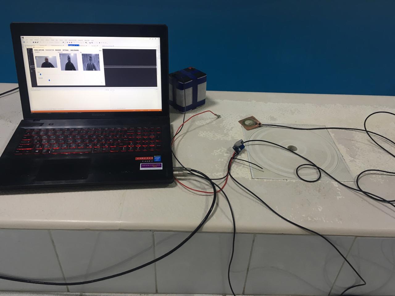
We connect the antenna that is intended for transmission to the amplifier board with aliexpress . For several tens of meters (maybe even hundreds), this is quite enough for us. There are no tricks here - the output of the laptop’s sound card goes to the input of the amplifier, which is powered by a 12 volt 4 Ah lead-acid battery. Our hydroacoustic transmitting antenna from a piezo tweeter is connected to the output. In my case, it looks like this:
In the photo above, on the screen there is a small spoiler for the next article. Next time on the same glands we will again try to transmit the "video" sound through water, but in a completely different way than last time .
With a receiving antenna is somewhat more complicated. Although piezo tweeters are very sensitive, this is still not enough. We will have to assemble a preamplifier board with a filter on the 5-35 kHz band.
We take 1000 gain.
The circuit, the design of the circuit board and the list of preamp components are on our GitHub: circuit , tracks - the top layer and the bottom layer , BOM . LUT
technology has been discussed hundreds of times, but let us also do our bit.
Process photo
So, we take a suitable magazine, we only had this one at hand:

We take a couple of pages from there and print the layers on them using a laser printer.

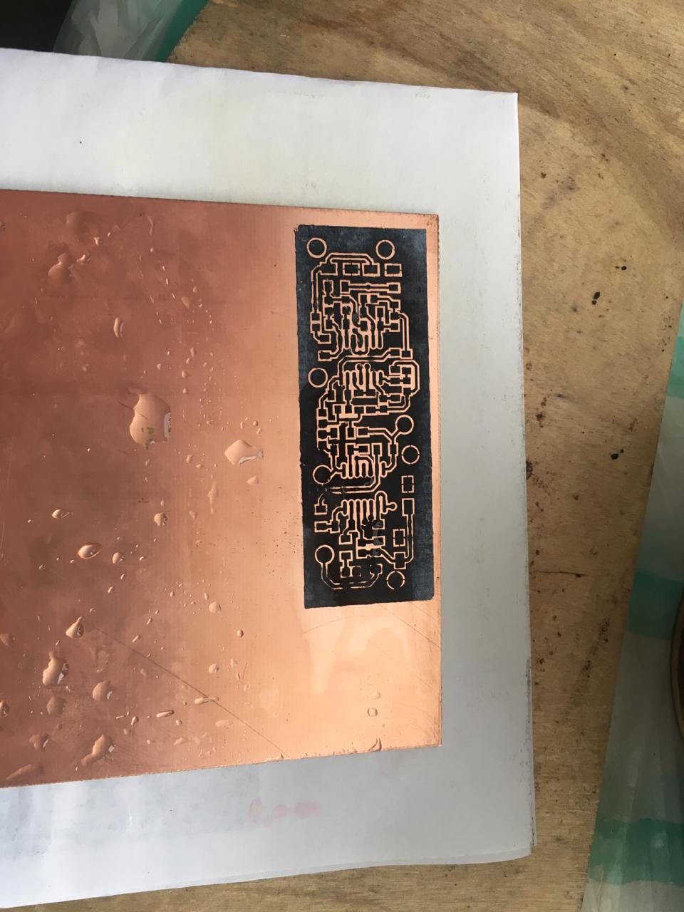
Combine with needles and glue on one side, as shown in the photo:

Before using the iron, moisten the toner with isopropyl alcohol:

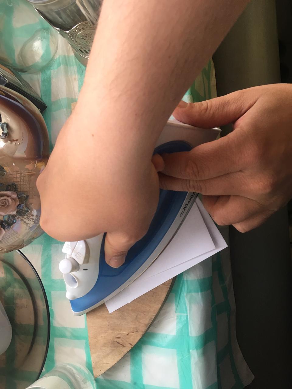
Iron through A4 sheet folded four times:
Soak in warm water under the tap:

And wash the remaining paper. Then we get a workpiece ready for etching: We
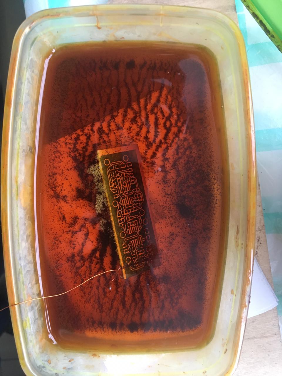
cut off the excess with scissors for metal or to whom it is more convenient.
We poison in ferric chloride. Especially for the article, we threw fresh, it turned out to be so picky that bubbles actively come from the future board:
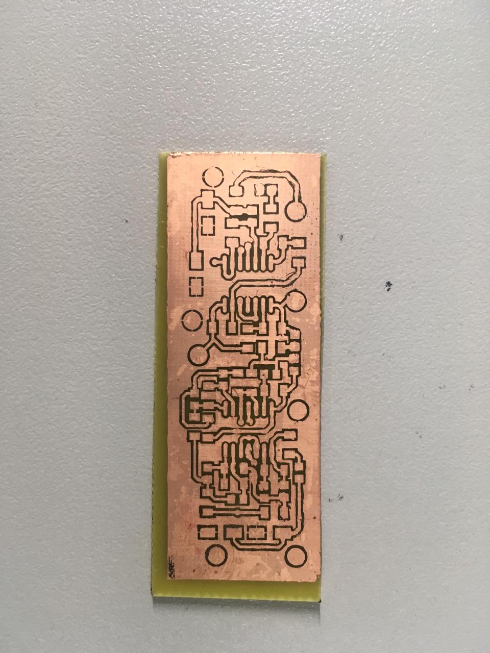
As a result, after etching and washing the toner, we get such a semi-finished product:
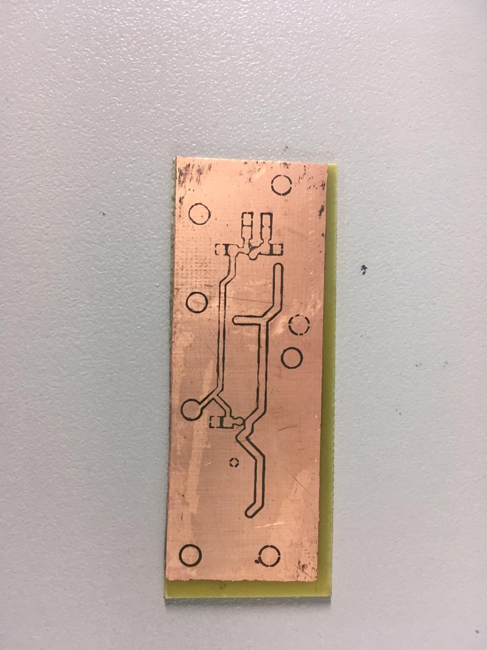
After soldering the components and washing the board will look like this.
We take a couple of pages from there and print the layers on them using a laser printer.
Combine with needles and glue on one side, as shown in the photo:
Before using the iron, moisten the toner with isopropyl alcohol:
Iron through A4 sheet folded four times:
Soak in warm water under the tap:
And wash the remaining paper. Then we get a workpiece ready for etching: We
cut off the excess with scissors for metal or to whom it is more convenient.
We poison in ferric chloride. Especially for the article, we threw fresh, it turned out to be so picky that bubbles actively come from the future board:
As a result, after etching and washing the toner, we get such a semi-finished product:
After soldering the components and washing the board will look like this.
And it looks like the receiving part assembly. Power is supplied from the same lead battery of 12 volts:
Small filter disclaimer
If the reader wants to change the band, then we propose to recount the 8th order filter assembled on a cheap 4-channel opamp TL084C (DA2 in the diagram ), resistors R10-R13, R15-R23 and capacitors C5-C8, C11, C12, C14 and C15.
Just in case, here we give the frequency response of the current filter implementation:
And here is another project for this filter created in the Qucs application
Just in case, here we give the frequency response of the current filter implementation:
And here is another project for this filter created in the Qucs application
Experiences and tests
To connect to a laptop we use a regular Jack 3.5 mm, the very tip is a signal, the middle one is not connected, the earth -
If you simply put one piece on another without an amplifier and preamplifier and connect them to the audio input and output, then everything works perfectly. Below is a section of the signal and you can even determine by eye where are the values of the bits:
The signal itself is shown in blue, the difference between the current and previous values of the amplitude (front) in red, and the difference between the previous and current values (decline) in green. You can easily “demodulate” this part of the premise: 1 0 0 0 1 1 0. Our zero is twice as long as unity, and the duration of the guard interval is equal to the duration of zero.
Further, also without an amplifier and preamplifier, we lower our antennas into a metal tank, with dimensions 3x1.5x1.5. We have this in the laboratory, and we made a rule that we don’t do any communication if she is somehow not able to work in this tank. The fact is that in such a closed volume of energy there is nowhere to go - the sound is wonderfully and repeatedly reflected from the metal walls and at the point of reception porridge is obtained. And given the fact that we usually check ready-made devices with energy calculated for thousands of meters, you can imagine what is going on there.
For example, our two RedLINE modems work stably in this tank only at a distance of no more than two meters, and two uWAVE-A stable work at about 1 meter. While the first in open water works up to 8000 meters, and the second - up to a kilometer .
Of course, all commercial products do not use such primitive modulation schemes, which are discussed in the article and are much more complicated, but it is important for us now to understand the basics and usefully do something with our hands.
In general, we lower the antennas into the tank to a distance of about 50 centimeters and we already get something much less beautiful than with the direct contact of the antennas:
Although a much longer guard interval is used here, it is still clear that the echo walks almost to the next bit, edges and especially recessions are very blurry. But you can still determine the content of the message: 1 0 0 0 1 1 0
In both cases, I sent the message “123” and these seven bits belong to the unit symbol.
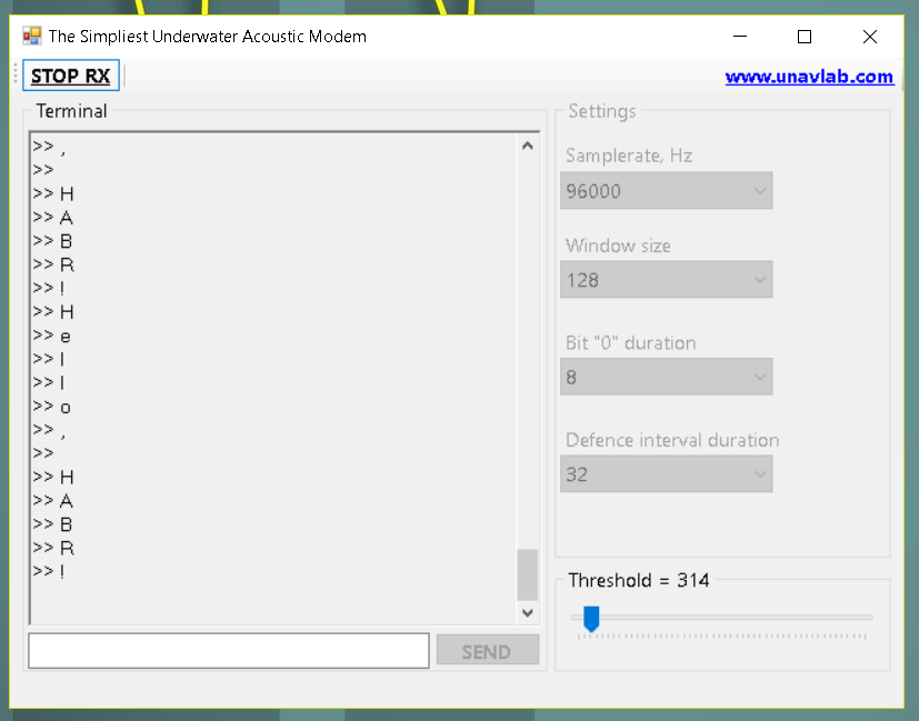
It looked something like this, then the interface was redone a bit.

From the screen above it can be seen that with those settings, the message “Hello, habr !!! :-) "consisting of 19 bytes takes 9.132 seconds, that is, the transmission speed was 16.6 bits / s. By the way, in order for the modem to work in our tank, we had to increase the guard interval so that the transmission speed dropped to ~ 3 bit / s.
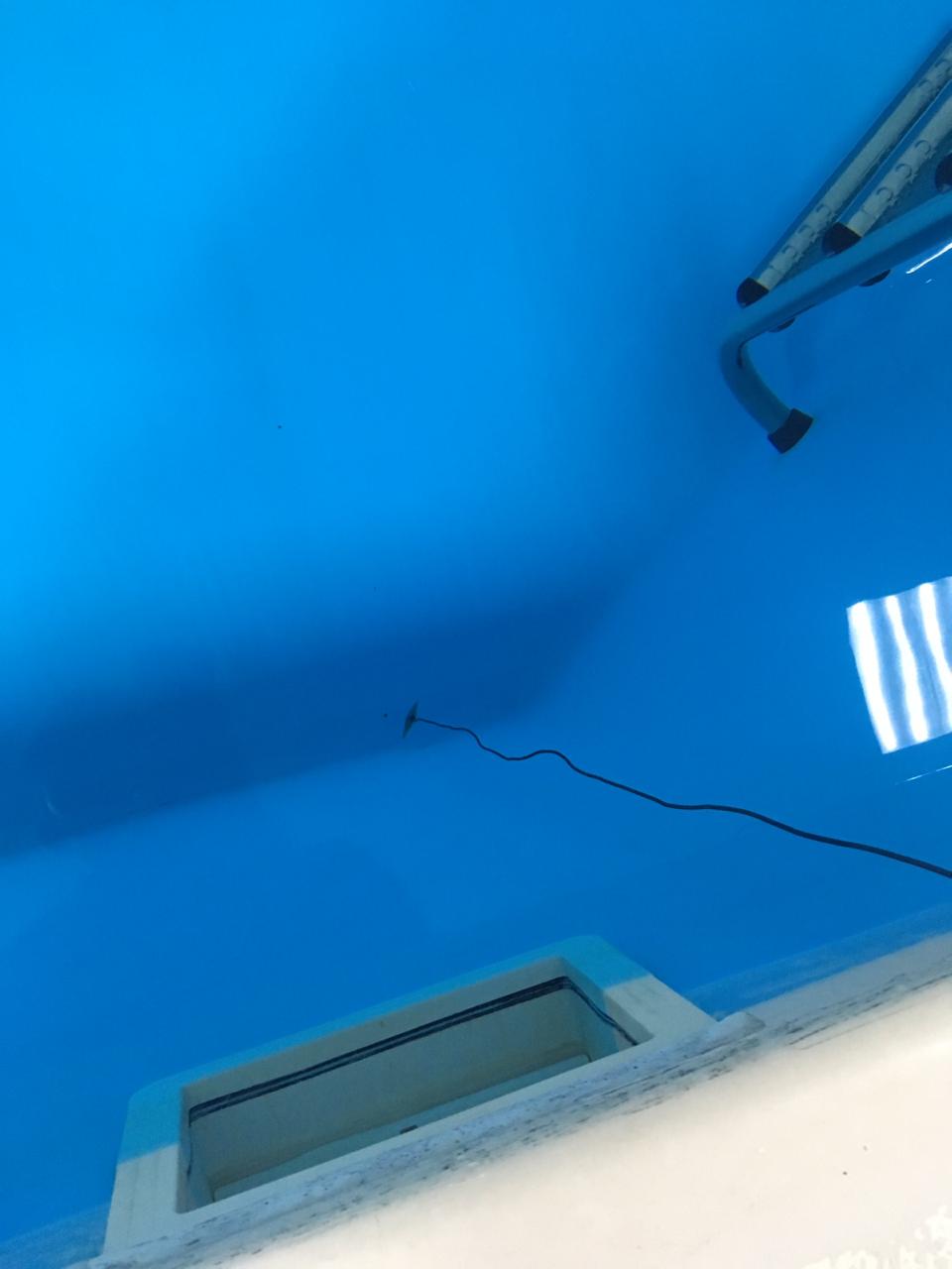
We checked the homemade work in the swimming pool, where it steadily earned 10 meters.
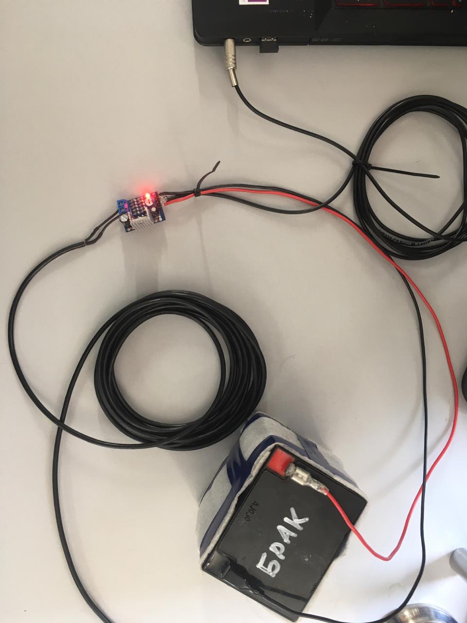
We also indulged in homemade work on the pond. I used an active hydrophone very similar in design to the one proposed in the article, only instead of a piezo pickup, a sensor from the parking sensors is used there, the battery is mounted there in a coil on which the cable is wound: The

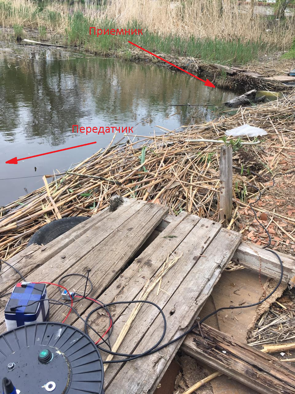
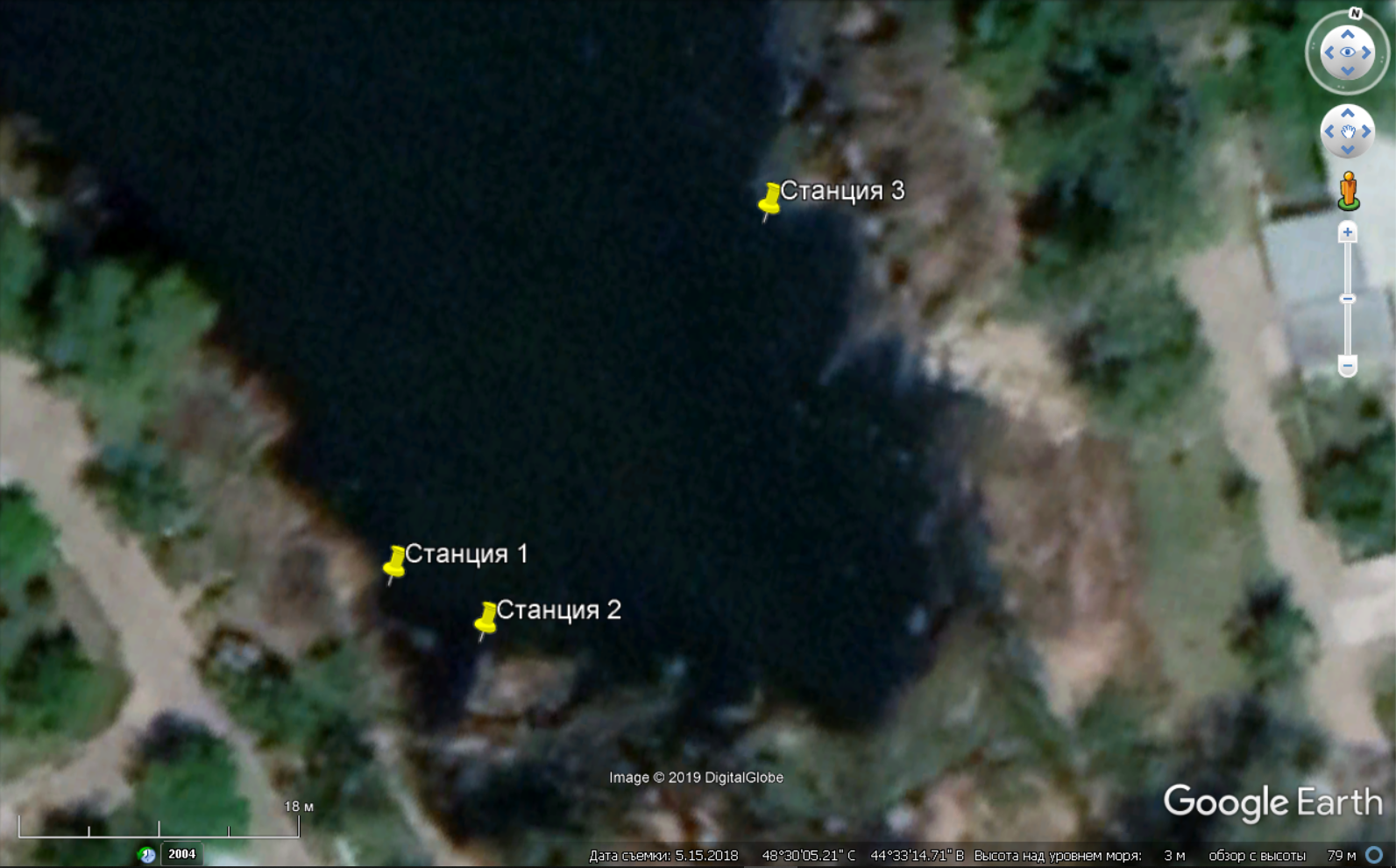
antennas of the receiver and transmitter descended directly from the shore, the depth there sharply goes from 0.5 to 2 meters. Oddly enough, in the experiment shown in the photo above, the worst conditions were, the distance there was only about 5 meters - this was generally the initial setting. Of the 20 transmitted messages, 3 bytes each, in six of them one byte was beaten.
Then, when we connected the receiver to a second laptop and moved it to the other side of the pond (distance of about 30 meters), the transmission went much better - there were only a couple of errors with 40 messages ranging in size from 3 to 13 bytes.
In the next photo on the map, the places where the antennas were located are visible.
Conclusion and further research
As promised, for a few rubles we have assembled a working device. Although its practical value is doubtful, the process of manufacturing and tuning on a pond will be very useful for beginners. Using the described carrier detection method, it is quite possible to come up with various simple navigation systems for amateur use, and what is especially nice, the computational complexity allows you to implement the method on a simple microcontroller.
In order not to be unfounded regarding the construction of navigation systems on simple signals, take a look at an interesting work, which built a full-fledged long-range navigation system. In this system, the position of the pinger is determined, which periodically transmits its depth. The depth value is encoded by the distance between two simple pulses at a certain frequency. So yes, yes, the pots are not burned by the gods, the road will be overpowered by the walker, patience and work, study, study, study - that’s all.
Perhaps, if we have time, we will do a DIY project for positioning an autonomous pinger emitting simple signals. We already did something similar, but not DIY, on the basis of our uWAVE modems , which we even tried to shoot a video about . It will be very interesting to hear your opinions on this matter - it is very important to have confirmation that you are doing something not in vain.
Nevertheless, returning to the main topic, we note what could be improved in the proposed scheme:
- make threshold calculation adaptive
- analyze signal widths automatically
- try using different lengths for different bit combinations
- tie
obozhebozhenoiseless coding - transfer it all to arduino
- the volume and threshold have to be long and tedious to select, so it would be nice to add AGC to the preamplifier
На этом заседание объявлю закрытым, а если вас заинтересовала тема, вот список наших предыдущих статей:
Подводный GPS с нуля за год
Подводный GPS на подводном роботе: опыт использования
Мы сделали самый маленький в мире гидроакустический модем
К вопросу о влиянии цианобактерий на речевые функции президента
Делаем простую гидроакустическую антенну из мусора
Сеанс передачи видео звуком через воду с разоблачением
Подводный «GPS» на двух приемопередатчиках
Навигация под водой: пеленгуй не пеленгуй — обречен ты на успех
Подводный GPS: продолжение
P.S.
Как всегда с удовольствием выслушаем замечания и предложения, обоснованную критику и одобряющие возгласы )
P.P.S.
Do not remove the glands far - next time we will use them again to transmit the "video" through the water.