About antennas for the smallest
Let’s try to figure out how antennas work and why electromagnetic energy from a comfortable conductor is radiated into a foreign dielectric, and we can do without matan, which, of course, will require very serious simplifications and even vulgarization, but it still allows you to get an initial idea and, I do not exclude, the desire to read materials for more advanced ones.
If you are a radio engineer, an experienced amateur radio operator, or just know the physics well, then reading the following is strictly not recommended to you in order to avoid negative consequences for your mental health. You were warned.
Let's start with the boring basics. In the good old days, when there was neither the Internet, nor this fido of yours, the well-known phenomena of electricity and magnetism were not considered as something single, having a common nature, until exactly two hundred years ago, the Danish Oersted discovered that the flow of electric current through a conductor causes a deviation compass needle i.e. creates a magnetic field accessible to observation and measurement by simple devices.
Soon, the Frenchman Ampère deduced a law of the name of himself, which describes the dependence of the electric current and the magnetic field arising from it, and a little later the included Englishman Faraday discovered and mathematically stated the phenomenon of electromagnetic induction. After quite a bit of time, the Scot Maxwell creates a theory of the electromagnetic field, which we should rely on in the subsequent story, but we agreed to do without matan as much as possible, so that even the most inveterate humanities could feel a taste for technology instead of being scared by complex formulas. All these works led to the fact that in 1887 the German Hertz experimentally proved the existence of radio waves by constructing a radio transmitter and radio receiver, which, quite unexpectedly, turned out to be working. However, Hertz himself is the prospect of his broadcast (the first in the world! ) did not appreciate and therefore the invention of radio is more often associated with the Italian Marconi, who, in addition to the undeniable engineering genius, was successful in terms of commercialization. Yes, if anyone is interested, the first broadcast of the voice belongs to the Canadian Fesenden, who managed to crank up this matter in 1900.

The current in the conductor creates a magnetic field. Why do we take our bare wire? Then, in order to easily remember the direction of the magnetic field vector, depending on the direction of the current in the conductor - the "rule of the right hand."
So, now we know that the flow of electric current in a conductor leads to the fact that a magnetic field arises near the conductor. This, if very, very simplified, is electromagnetism. Therefore, the first thing we can learn: the radiation of antennas is associated with the flow of electric current in them.
Radio communication uses alternating current of various frequencies (or wavelengths - speaking about antennas it is often more convenient to talk about wavelengths, and about radio engineering as a whole - about frequency).
Different frequencies allow you to simultaneously conduct many independent transmissions and share their reception, choosing the right frequencies and discarding unnecessary. There are quite a few ways to do this, but they are the topic of separate articles. Alternating current has one unpleasant feature: although it fully obeys Ohm's law (the interdependence of voltage, circuit resistance and current in it), voltage and current may not coincide in time. Yes, “phase shift” is not necessarily in the head; it is more than an electrical and radio engineering term. Here is the result. If we applied an alternating voltage to some ideal resistor, then the common-mode alternating current in this circuit would be equal to the voltage in volts divided by the resistance in ohms - just like a decent direct current. But if instead of a resistor we have an inductor, then things get more confusing. When we apply voltage to the coil, it resists the current through it, so the current lags the phase of the voltage. By the way, if you disconnect the voltage supply from the coil, then it will also resist and try to maintain the flow of current through itself (to the extent that the coil can store energy) - there is no voltage anymore, but the current is still flowing. This is this resistance, it is called reactive, the higher, the higher the frequency. That is, with increasing frequency with equal inductance or with increasing inductance with equal frequency, the resistance to alternating current increases. With capacitors, everything is the same, but just the opposite. When voltage is applied to the capacitor, the current first falls into it, as in an empty hole, ahead of the voltage, and then drops as it charges. Ease, with which the alternating current enters the capacitor, means that with increasing frequency with equal capacitance, the resistance to alternating current drops, and with an equal frequency with increasing capacitance, the resistance to alternating current also drops. Therefore, we take a note: reactance, that is, inductive or capacitive resistance to alternating current, depends on the frequency.
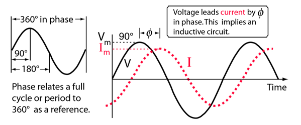
On the left is a traditional sinusoidal waveform, on the right is a phase shift on the example of a "lag" of the current from the voltage when there is inductive resistance in the circuit.
The total resistance, consisting of the active component (a conditional resistor that consumes power “purely” without affecting the phase) and the reactive component (phase-shifting inductance and / or capacitance), is called the complex resistance or impedance.
So, an antenna is a conductor to which electric energy is supplied and which radiates it into the surrounding space. It emits an electric current in a conductor, which creates a magnetic field around the conductor.
Why does electromagnetic energy leave a conductor that is comfortable for her and into an uncomfortable vacuum for her? But she doesn’t come out! Energy creates field vibrations, but does not move by itself. Let's compare with sound waves. When a speaker (antenna) creates vibrations, air (ether) does not move, wind does not occur, but vibrations propagate in air (ether). The same thing happens with electromagnetic waves, except that electromagnetic energy does not propagate in the air, but in the ether. Later, however, they will find out that the proposed ether does not exist, and that the earth is also not flat, and the electromagnetic field also feels fine in a vacuum,but we know that there is ether, and the earth, of course, is not flat, but slightly convex. That is, once again, energy is not transferred together with the medium (more precisely, with the field), but is transferred due to the propagation of waves in a generally motionless medium (in the field).
Antenna as an oscillatory circuit. Before talking about the specific designs of simple antennas, according to the principle of the device of which we can also understand the device complex, let's talk about electrical resonance. To do this, let's go back to reactance. The antenna sheet can be represented as a distributed capacitance and a distributed inductance - as a coil unwound to a straight wire and as capacitor plates degenerated to the same wire. The presence of reactance in the circuit, as we recall, separates the phases of current and voltage. However, if we select a certain combination of inductance and capacitance (and this will work only at one certain frequency, because we remember that with a change in frequency the reactance changes), then it turns out, that the capacitance and inductance cancel each other out and we see a purely active resistance in the load. Here is such a mutual compensation and the result in the form of a purely active resistance as the result of compensation is called electrical resonance. By itself, it is unimportant for the antenna to work, because the antenna, as we have already found out, emits current in the conductor. However, there are a number of reasons why they tend to achieve resonance in the antenna. The fact is that, unlike direct current, for an alternating current it is important that the wave impedance (I recall Ohm's law, namely that the circuit resistance is numerically equal to the applied voltage divided by the current) of the generator, transmission line and load, i.e. the antennas themselves were equal. If there is no equality, part of the electromagnetic energy will be reflected back to the generator, leading to a whole range of adverse events. Significant reactance leads to strong mismatch and significant reflection of energy. However, this also applies to the active component of the impedance, which is easier to coordinate with an insignificant, easily compensated reactive component. Therefore, technically they are trying to create such antennas in which the reactive component is absent or easily compensated, and the active component is equal to the wave impedance of the generator or is easily transformed. In the case of the simplest antennas, creating a specific antenna capacitance or a certain inductance simply means sizing. Therefore, usually the dimensions of the antennas are measured not in linear units, but in fractions of the wavelength. this also applies to the active component of the impedance, which is easier to coordinate with an insignificant, easily compensated reactive component. Therefore, technically they are trying to create such antennas in which the reactive component is absent or easily compensated, and the active component is equal to the wave impedance of the generator or is easily transformed. In the case of the simplest antennas, creating a specific antenna capacitance or a certain inductance simply means sizing. Therefore, usually the dimensions of the antennas are measured not in linear units, but in fractions of the wavelength. this also applies to the active component of the impedance, which is easier to coordinate with an insignificant, easily compensated reactive component. Therefore, technically they are trying to create such antennas in which the reactive component is absent or easily compensated, and the active component is equal to the wave impedance of the generator or is easily transformed. In the case of the simplest antennas, creating a specific antenna capacitance or a certain inductance simply means sizing. Therefore, usually the dimensions of the antennas are measured not in linear units, but in fractions of the wavelength. and the active is equal to the wave impedance of the generator or is easily transformed. In the case of the simplest antennas, creating a specific antenna capacitance or a certain inductance simply means sizing. Therefore, usually the dimensions of the antennas are measured not in linear units, but in fractions of the wavelength. and the active is equal to the wave impedance of the generator or is easily transformed. In the case of the simplest antennas, creating a specific antenna capacitance or a certain inductance simply means sizing. Therefore, usually the dimensions of the antennas are measured not in linear units, but in fractions of the wavelength.
The simplest full-size antennas. Half-wave dipole, quarter-wave groundplein and similar designs.

As you can see, the distribution of currents and voltages is the same. Only if in the quarter-wave groundplein one half of the dipole is a pin, and the second half is the earth, then in the half-wave dipole - the second half is its second half. :)
To get acquainted with the principles that are the same for any more complex antennas, I propose to deal with the design and operation of the basic antennas - a symmetric half-wave dipole or an asymmetric quarter-wave groundplein. To a certain extent, they are identical and a half-wave dipole can be considered as an extreme case of a quarter-wave groundplein, the angle of radials (balances) of which reached 180 ° to the emitting pin, so most of the features considered are equally applicable to both antennas.
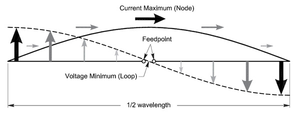
As you can see, such an antenna has electrical resonance, because an integer number of half-waves of current and an integer number of half-waves of voltage are placed in its conductor. They are phase shifted relative to each other, but their reactivity is mutually compensated.
If the antenna were a little shorter than the half-wave, then it would have a capacitive component of the impedance and it would have to be compensated by inductance (does it not remind anyone of the coils at the base of the sibishnaya auto-antennas?), But if on the contrary lengthen, an inductive component appears that needs to be compensated by the capacitance .
Radiation resistance. There is nothing special about radiation resistance. More truly not so. Radiation resistance in the physical sense does not exist, it is an analytical value that is used to determine the antenna efficiency. The easiest way to imagine the radiation resistance is that active component of the total resistance of the entire antenna, which is spent on radiation. Actually, there is the term “radiation loss” and this is a useful “loss” if we are talking about an antenna, but this is not equal to the radiation resistance, so do not confuse. There is no imaginary resistance of the medium to the imaginary radiation into it or anything else - there are different properties like permittivity, which we will not consider for now.
There is also a loss resistance in the antenna in the form of the resistance of a conductor, which is spent on its heating, various losses in structural elements and matching links. A knowledge of the radiation resistance is necessary for understanding the efficiency of the antenna: for some antennas, the radiation resistance can be units and fractions of Ohm, while the loss resistance is several times greater, which means that the efficiency of such an antenna is extremely low despite the fact that its design is otherwise adequate. In simple antennas like the dipole or groundplein under consideration, the radiation resistance is close to the total resistance of the antenna itself, because the losses in the conductor are relatively small, but in any case they are not identical concepts.
Let's go back to the dipole. As long as we supply energy in its geometric center, where the current is maximum and the voltage is minimum, the radiation resistance is small. Theoretically, it is approximately 73 ohms, and almost slightly less depending on the relative thickness of the material. As one of the halves of the dipole splits into separate radii, the resistance will decrease slightly and drop to approximately 36 Ohm mi at a 90 ° angle to the pin. This obviously affects the antenna efficiency. But, for clarity, we will consider just a dipole. As the supply point shifts from the center to the edge, we will see that the current decreases and the voltage increases, that is, the radiation resistance increases, which reaches its maximum when powered from the end. This circumstance does not affect all other characteristics of the antenna, it still emits with the same radiation pattern,
The antenna impedance is equal to the voltage at the power point divided by the output current. And it consists of, as we have already found out, the radiation resistance, on which we usefully lose energy to the radiation we need, and the loss resistance, on which we lose energy, is useless. In many ways, we can influence the antenna impedance. Without changing the geometry, we can shift the power point. We can use various transforming elements (including literally transformers with windings at those frequencies at which their use is rational). All these manipulations have no effect on the radiation efficiency of the antenna and are needed only for matching the antenna with the generator (transmitter). For example, a half-wave dipole with a center feed, whose resistance is approximately 73 Ohms, through a simple transformer 1: 4 may be consistent with the generator, designed for an antenna with a resistance of 18 ohms or 300 ohms - depending on how to connect the leads. This will not affect the operation of the antenna except the influence of losses in the transformer on the efficiency of the entire assembly.
If it seems to you that the antenna has only a monopole - a pin, a piece of wire or just a track on the printed circuit board, then this is actually a variant of the groundplein, which does not have specially allocated radials, but the earth, the body of the operator (a portable radio station, for example ) or landfills on the board. Losses in such radii are obviously greater than in those specially designed as part of the antenna, therefore the efficiency of such structures is always lower, as well as the degree of matching of impedances due to the unpredictability of situational radiations instead of calculated ones.
With an increase in the length of the antenna over the half-wave dipole, the radiation resistance first increases, reaching a maximum at an even number of half-waves, and then falls again, reaching a minimum at an odd number of half-waves. A slight increase in length narrows the radiation pattern and increases the transmission efficiency in the selected direction, while a significant one leads to a fragmentation of the pattern into many lobes and is generally inefficient, therefore it is usually not used in practice except for multi-band antennas, in which this is a compromise solution.
In general, any increase in the length of the dipole in excess of half the wave leads to the fact that on the canvas there are areas where the current flows in the opposite direction. This current, of course, also participates in the radiation, but the interference of the field created by it with the field of the conditionally main part of the canvas causes the radiation pattern to split, which is harmful in most cases: usually, radio communication is carried out in one or several known directions and the radiation in The "unnecessary" side simply means wasted losses. For example, terrestrial communication is conducted in the direction of the horizon, and radiation into space is wasting the power of the transmitter uselessly. Therefore, when it is necessary to increase the directivity of the antenna in order to send energy more focused in the right direction, they prefer to use more complex structures based on a dipole,
When the length of the antenna decreases from the half-wave dipole (or the shortening of the quarter-wave groundplen pin), the radiation resistance decreases exponentially, which, together with an increasingly complicated matching device, makes the shortened antenna extremely inefficient - a small radiation resistance near a large resistance means the heating of the matching device with low radiation is in vain.
That, in fact, is all that the humanities need to know about antennas.
If you are a radio engineer, an experienced amateur radio operator, or just know the physics well, then reading the following is strictly not recommended to you in order to avoid negative consequences for your mental health. You were warned.
Let's start with the boring basics. In the good old days, when there was neither the Internet, nor this fido of yours, the well-known phenomena of electricity and magnetism were not considered as something single, having a common nature, until exactly two hundred years ago, the Danish Oersted discovered that the flow of electric current through a conductor causes a deviation compass needle i.e. creates a magnetic field accessible to observation and measurement by simple devices.
Soon, the Frenchman Ampère deduced a law of the name of himself, which describes the dependence of the electric current and the magnetic field arising from it, and a little later the included Englishman Faraday discovered and mathematically stated the phenomenon of electromagnetic induction. After quite a bit of time, the Scot Maxwell creates a theory of the electromagnetic field, which we should rely on in the subsequent story, but we agreed to do without matan as much as possible, so that even the most inveterate humanities could feel a taste for technology instead of being scared by complex formulas. All these works led to the fact that in 1887 the German Hertz experimentally proved the existence of radio waves by constructing a radio transmitter and radio receiver, which, quite unexpectedly, turned out to be working. However, Hertz himself is the prospect of his broadcast (the first in the world! ) did not appreciate and therefore the invention of radio is more often associated with the Italian Marconi, who, in addition to the undeniable engineering genius, was successful in terms of commercialization. Yes, if anyone is interested, the first broadcast of the voice belongs to the Canadian Fesenden, who managed to crank up this matter in 1900.
The current in the conductor creates a magnetic field. Why do we take our bare wire? Then, in order to easily remember the direction of the magnetic field vector, depending on the direction of the current in the conductor - the "rule of the right hand."
So, now we know that the flow of electric current in a conductor leads to the fact that a magnetic field arises near the conductor. This, if very, very simplified, is electromagnetism. Therefore, the first thing we can learn: the radiation of antennas is associated with the flow of electric current in them.
Radio communication uses alternating current of various frequencies (or wavelengths - speaking about antennas it is often more convenient to talk about wavelengths, and about radio engineering as a whole - about frequency).
Different frequencies allow you to simultaneously conduct many independent transmissions and share their reception, choosing the right frequencies and discarding unnecessary. There are quite a few ways to do this, but they are the topic of separate articles. Alternating current has one unpleasant feature: although it fully obeys Ohm's law (the interdependence of voltage, circuit resistance and current in it), voltage and current may not coincide in time. Yes, “phase shift” is not necessarily in the head; it is more than an electrical and radio engineering term. Here is the result. If we applied an alternating voltage to some ideal resistor, then the common-mode alternating current in this circuit would be equal to the voltage in volts divided by the resistance in ohms - just like a decent direct current. But if instead of a resistor we have an inductor, then things get more confusing. When we apply voltage to the coil, it resists the current through it, so the current lags the phase of the voltage. By the way, if you disconnect the voltage supply from the coil, then it will also resist and try to maintain the flow of current through itself (to the extent that the coil can store energy) - there is no voltage anymore, but the current is still flowing. This is this resistance, it is called reactive, the higher, the higher the frequency. That is, with increasing frequency with equal inductance or with increasing inductance with equal frequency, the resistance to alternating current increases. With capacitors, everything is the same, but just the opposite. When voltage is applied to the capacitor, the current first falls into it, as in an empty hole, ahead of the voltage, and then drops as it charges. Ease, with which the alternating current enters the capacitor, means that with increasing frequency with equal capacitance, the resistance to alternating current drops, and with an equal frequency with increasing capacitance, the resistance to alternating current also drops. Therefore, we take a note: reactance, that is, inductive or capacitive resistance to alternating current, depends on the frequency.
On the left is a traditional sinusoidal waveform, on the right is a phase shift on the example of a "lag" of the current from the voltage when there is inductive resistance in the circuit.
The total resistance, consisting of the active component (a conditional resistor that consumes power “purely” without affecting the phase) and the reactive component (phase-shifting inductance and / or capacitance), is called the complex resistance or impedance.
So, an antenna is a conductor to which electric energy is supplied and which radiates it into the surrounding space. It emits an electric current in a conductor, which creates a magnetic field around the conductor.
Why does electromagnetic energy leave a conductor that is comfortable for her and into an uncomfortable vacuum for her? But she doesn’t come out! Energy creates field vibrations, but does not move by itself. Let's compare with sound waves. When a speaker (antenna) creates vibrations, air (ether) does not move, wind does not occur, but vibrations propagate in air (ether). The same thing happens with electromagnetic waves, except that electromagnetic energy does not propagate in the air, but in the ether. Later, however, they will find out that the proposed ether does not exist, and that the earth is also not flat, and the electromagnetic field also feels fine in a vacuum,
Antenna as an oscillatory circuit. Before talking about the specific designs of simple antennas, according to the principle of the device of which we can also understand the device complex, let's talk about electrical resonance. To do this, let's go back to reactance. The antenna sheet can be represented as a distributed capacitance and a distributed inductance - as a coil unwound to a straight wire and as capacitor plates degenerated to the same wire. The presence of reactance in the circuit, as we recall, separates the phases of current and voltage. However, if we select a certain combination of inductance and capacitance (and this will work only at one certain frequency, because we remember that with a change in frequency the reactance changes), then it turns out, that the capacitance and inductance cancel each other out and we see a purely active resistance in the load. Here is such a mutual compensation and the result in the form of a purely active resistance as the result of compensation is called electrical resonance. By itself, it is unimportant for the antenna to work, because the antenna, as we have already found out, emits current in the conductor. However, there are a number of reasons why they tend to achieve resonance in the antenna. The fact is that, unlike direct current, for an alternating current it is important that the wave impedance (I recall Ohm's law, namely that the circuit resistance is numerically equal to the applied voltage divided by the current) of the generator, transmission line and load, i.e. the antennas themselves were equal. If there is no equality, part of the electromagnetic energy will be reflected back to the generator, leading to a whole range of adverse events. Significant reactance leads to strong mismatch and significant reflection of energy. However, this also applies to the active component of the impedance, which is easier to coordinate with an insignificant, easily compensated reactive component. Therefore, technically they are trying to create such antennas in which the reactive component is absent or easily compensated, and the active component is equal to the wave impedance of the generator or is easily transformed. In the case of the simplest antennas, creating a specific antenna capacitance or a certain inductance simply means sizing. Therefore, usually the dimensions of the antennas are measured not in linear units, but in fractions of the wavelength. this also applies to the active component of the impedance, which is easier to coordinate with an insignificant, easily compensated reactive component. Therefore, technically they are trying to create such antennas in which the reactive component is absent or easily compensated, and the active component is equal to the wave impedance of the generator or is easily transformed. In the case of the simplest antennas, creating a specific antenna capacitance or a certain inductance simply means sizing. Therefore, usually the dimensions of the antennas are measured not in linear units, but in fractions of the wavelength. this also applies to the active component of the impedance, which is easier to coordinate with an insignificant, easily compensated reactive component. Therefore, technically they are trying to create such antennas in which the reactive component is absent or easily compensated, and the active component is equal to the wave impedance of the generator or is easily transformed. In the case of the simplest antennas, creating a specific antenna capacitance or a certain inductance simply means sizing. Therefore, usually the dimensions of the antennas are measured not in linear units, but in fractions of the wavelength. and the active is equal to the wave impedance of the generator or is easily transformed. In the case of the simplest antennas, creating a specific antenna capacitance or a certain inductance simply means sizing. Therefore, usually the dimensions of the antennas are measured not in linear units, but in fractions of the wavelength. and the active is equal to the wave impedance of the generator or is easily transformed. In the case of the simplest antennas, creating a specific antenna capacitance or a certain inductance simply means sizing. Therefore, usually the dimensions of the antennas are measured not in linear units, but in fractions of the wavelength.
The simplest full-size antennas. Half-wave dipole, quarter-wave groundplein and similar designs.
As you can see, the distribution of currents and voltages is the same. Only if in the quarter-wave groundplein one half of the dipole is a pin, and the second half is the earth, then in the half-wave dipole - the second half is its second half. :)
To get acquainted with the principles that are the same for any more complex antennas, I propose to deal with the design and operation of the basic antennas - a symmetric half-wave dipole or an asymmetric quarter-wave groundplein. To a certain extent, they are identical and a half-wave dipole can be considered as an extreme case of a quarter-wave groundplein, the angle of radials (balances) of which reached 180 ° to the emitting pin, so most of the features considered are equally applicable to both antennas.
As you can see, such an antenna has electrical resonance, because an integer number of half-waves of current and an integer number of half-waves of voltage are placed in its conductor. They are phase shifted relative to each other, but their reactivity is mutually compensated.
If the antenna were a little shorter than the half-wave, then it would have a capacitive component of the impedance and it would have to be compensated by inductance (does it not remind anyone of the coils at the base of the sibishnaya auto-antennas?), But if on the contrary lengthen, an inductive component appears that needs to be compensated by the capacitance .
Radiation resistance. There is nothing special about radiation resistance. More truly not so. Radiation resistance in the physical sense does not exist, it is an analytical value that is used to determine the antenna efficiency. The easiest way to imagine the radiation resistance is that active component of the total resistance of the entire antenna, which is spent on radiation. Actually, there is the term “radiation loss” and this is a useful “loss” if we are talking about an antenna, but this is not equal to the radiation resistance, so do not confuse. There is no imaginary resistance of the medium to the imaginary radiation into it or anything else - there are different properties like permittivity, which we will not consider for now.
There is also a loss resistance in the antenna in the form of the resistance of a conductor, which is spent on its heating, various losses in structural elements and matching links. A knowledge of the radiation resistance is necessary for understanding the efficiency of the antenna: for some antennas, the radiation resistance can be units and fractions of Ohm, while the loss resistance is several times greater, which means that the efficiency of such an antenna is extremely low despite the fact that its design is otherwise adequate. In simple antennas like the dipole or groundplein under consideration, the radiation resistance is close to the total resistance of the antenna itself, because the losses in the conductor are relatively small, but in any case they are not identical concepts.
Let's go back to the dipole. As long as we supply energy in its geometric center, where the current is maximum and the voltage is minimum, the radiation resistance is small. Theoretically, it is approximately 73 ohms, and almost slightly less depending on the relative thickness of the material. As one of the halves of the dipole splits into separate radii, the resistance will decrease slightly and drop to approximately 36 Ohm mi at a 90 ° angle to the pin. This obviously affects the antenna efficiency. But, for clarity, we will consider just a dipole. As the supply point shifts from the center to the edge, we will see that the current decreases and the voltage increases, that is, the radiation resistance increases, which reaches its maximum when powered from the end. This circumstance does not affect all other characteristics of the antenna, it still emits with the same radiation pattern,
The antenna impedance is equal to the voltage at the power point divided by the output current. And it consists of, as we have already found out, the radiation resistance, on which we usefully lose energy to the radiation we need, and the loss resistance, on which we lose energy, is useless. In many ways, we can influence the antenna impedance. Without changing the geometry, we can shift the power point. We can use various transforming elements (including literally transformers with windings at those frequencies at which their use is rational). All these manipulations have no effect on the radiation efficiency of the antenna and are needed only for matching the antenna with the generator (transmitter). For example, a half-wave dipole with a center feed, whose resistance is approximately 73 Ohms, through a simple transformer 1: 4 may be consistent with the generator, designed for an antenna with a resistance of 18 ohms or 300 ohms - depending on how to connect the leads. This will not affect the operation of the antenna except the influence of losses in the transformer on the efficiency of the entire assembly.
If it seems to you that the antenna has only a monopole - a pin, a piece of wire or just a track on the printed circuit board, then this is actually a variant of the groundplein, which does not have specially allocated radials, but the earth, the body of the operator (a portable radio station, for example ) or landfills on the board. Losses in such radii are obviously greater than in those specially designed as part of the antenna, therefore the efficiency of such structures is always lower, as well as the degree of matching of impedances due to the unpredictability of situational radiations instead of calculated ones.
With an increase in the length of the antenna over the half-wave dipole, the radiation resistance first increases, reaching a maximum at an even number of half-waves, and then falls again, reaching a minimum at an odd number of half-waves. A slight increase in length narrows the radiation pattern and increases the transmission efficiency in the selected direction, while a significant one leads to a fragmentation of the pattern into many lobes and is generally inefficient, therefore it is usually not used in practice except for multi-band antennas, in which this is a compromise solution.
In general, any increase in the length of the dipole in excess of half the wave leads to the fact that on the canvas there are areas where the current flows in the opposite direction. This current, of course, also participates in the radiation, but the interference of the field created by it with the field of the conditionally main part of the canvas causes the radiation pattern to split, which is harmful in most cases: usually, radio communication is carried out in one or several known directions and the radiation in The "unnecessary" side simply means wasted losses. For example, terrestrial communication is conducted in the direction of the horizon, and radiation into space is wasting the power of the transmitter uselessly. Therefore, when it is necessary to increase the directivity of the antenna in order to send energy more focused in the right direction, they prefer to use more complex structures based on a dipole,
When the length of the antenna decreases from the half-wave dipole (or the shortening of the quarter-wave groundplen pin), the radiation resistance decreases exponentially, which, together with an increasingly complicated matching device, makes the shortened antenna extremely inefficient - a small radiation resistance near a large resistance means the heating of the matching device with low radiation is in vain.
That, in fact, is all that the humanities need to know about antennas.