PIM Principles
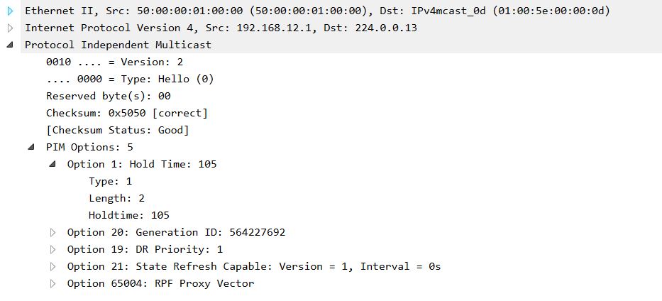
The PIM protocol is a set of protocols for transmitting multicast on a network between routers. Neighborhood relationships are built in the same way as in the case of dynamic routing protocols. PIMv2 sends Hello messages every 30 seconds to the reserved multicast address 224.0.0.13 (All-PIM-Routers). The message contains Hold Timers - usually 3.5 * Hello Timer, i.e. 105 seconds by default.
PIM uses two main modes of operation - Dense and Sparse mode. Let's start with Dense mode.
Source-Based Distribution Trees.
It is advisable to use the Dense-mode mode in the case of a large number of clients of various multicast groups. When a router receives multicast traffic, the first thing it does is check it for the RPF rule. RPF - this rule is used to check the source of a multicast with a unicast routing table. It is necessary that the traffic came to the interface behind which this host is hidden according to the version of the unicast routing table. This mechanism solves the problem of loop occurrence during multicast transmission.
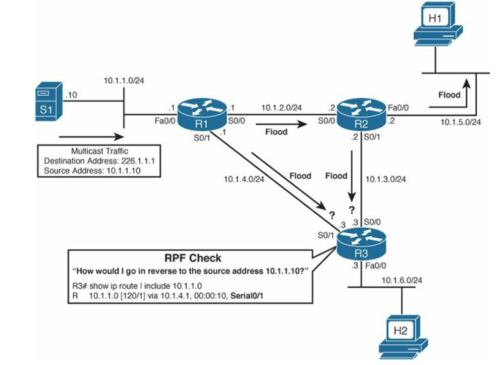
R3 from the multicast message recognizes the source of the multicast (Source IP) and checks the two streams from R1 and R2 from its unicast table. The stream from the interface indicated by the table (R1 to R3) will be transmitted further, and the stream from R2 will be dropped, because in order to get to the source of the multicast, it is necessary to send packets via S0 / 1.
The question is, what happens if you have two equivalent routes with the same metric? In this case, the router will choose next-hop for these routes. Who has a higher ip address, he won. If you need to change this behavior, you can use ECMP. More details here .
After checking the RPF rule, the router sends a multicast packet to all its PIM neighbors, except for the one from whom the packet was received. Other PIM routers repeat this process. The path that the multicast packet has passed from the source to the final recipients forms a tree called - source-based distribution tree, shortest-path tree (SPT), source tree. Three different names, choose any.
How to solve the problem with the fact that some routers didn’t give up some multicast stream and there is no one to send it to, and a higher-level router sends it. For this, the Prune mechanism was invented.
Prune Message.
For example, R2 will continue to send R3 multicast, although R3 by the rule of RPF drops it. Why load the channel? R3 sends a PIM Prune Message and R2, upon receiving this message, removes the S0 / 1 interface from the outgoing interface list for this stream, the list of interfaces from which this traffic should be sent.
After receiving the Prune message, R2 sets the Prune timer to 3 minutes. After three minutes, it will start sending traffic again until it receives the next Prune message. This is in PIMv1.
And in PIMv2 State Refresh timer is added (by default 60 seconds). As soon as Prune has sent a message with R3, this timer starts on R3. After this timer expires, R3 will send a State Refresh message that will reset the 3-minute Prune Timer to R2 for this group.
Reasons for sending a Prune message:
Graft Message.
Imagine that R3 did not want traffic from R2, sent Prune and received multicast from R1. But suddenly, the channel fell between R1-R3 and R3 was left without a multicast. You can wait 3 minutes until Prune Timer expires on R2. 3 minutes to wait a long time, so as not to wait, you need to send a message that instantly displays this interface S0 / 1 on R2 from the pruned state. This message will be a Graft message. After receiving the Graft message, R2 will send a Graft-ACK in response.
Prune Override.
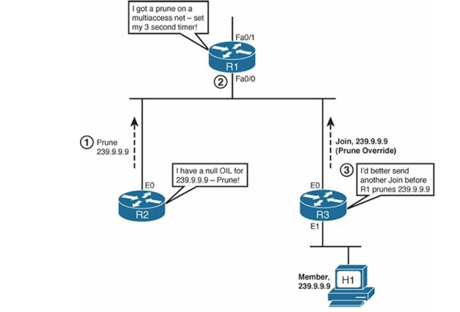
Let's look at this scheme. R1 broadcasts multicast in a segment with two routers. R3 receives and broadcasts traffic, R2 receives, but it has no one to broadcast traffic. It sends a Prune message to R1 in this segment. R1 should remove Fa0 / 0 from the list and stop broadcasting in this segment, but what will happen to R3? And R3 is in the same segment, he also received this message from Prune and realized the tragedy of the situation. Before R1 stops broadcasting, it sets the timer to 3 seconds and stops broadcasting after 3 seconds. 3 seconds - just so much time for R3, so as not to lose your multicast. Therefore, R3, as soon as possible, sends a Pim Join message for this group and R1 no longer thinks to stop broadcasting. About Join posts below.
Assert Message.
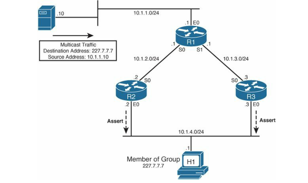
Imagine this situation: two routers broadcast to the same network at once. They receive the same stream from the source, and both broadcast it to the same network behind the e0 interface. Therefore, they need to determine who will be the only single broadcaster for this network. Assert messages are used for this. When R2 and R3 detect duplication of multicast traffic, that is, multicast that they broadcast on R2 and R3, which they themselves broadcast, the routers understand that something is wrong here. In this case, the routers send Assert messages, which include the Administrative Distance and the route metric by which the multicast source is reached - 10.1.1.10. The winner is determined as follows:
Winning this vote, the router becomes the Designated Router. Pim Hello is also used to select DR. At the beginning of the article, a PIM Hello message was shown, where you can notice the DR field. The winner is the one with a higher IP address on this link.
Useful plate: MROUTE Table. After the initial review of the operation of the PIM protocol, we need to figure out how to work with the multicast routing table. The mroute table stores information about which streams were requested by clients and which streams flow from multicast servers. For example, when receiving an IGMP Membership Report or PIM Join on some interface, an entry of the type (*, G) is added to the routing table:

This entry means that a traffic request was received with the address 238.38.38.38. The DC flag means that the multicast will work in Dense mode and C means that the recipient is directly connected to the router, that is, the router received the IGMP Membership Report, and PIM Join.
If there is a record like (S, G) means that we have a multicast stream:

In the S field - 192.168.1.11, we have the IP address of the multicast source registered, it will be checked by the RPF rule. In case of problems, the first thing to do is check the unicast table for the route to the source. In the Incoming Interface field indicates the interface to which the multicast arrives. In the unicast routing table, the route to the source must refer to the interface specified here. The Outgoing Interface indicates where the multicast will be redirected. If it is empty, then there were no requests for this traffic to the router. More information on all flags can be found here .
PIM Sparse-mode.
The Sparse-mode strategy is the opposite of Dense-mode. When Sparse-mode receives multicast traffic, it will send traffic only through those interfaces where there were requests for this stream, for example, Pim Join or IGMP Report messages requesting this traffic.
Similar elements for SM and DM:
To control who needs where, where and what multicast traffic is needed on the network, a common information center is needed. Such a center we will have Rendezvous Point (RP). Anyone who wants some kind of multicast traffic or someone started to receive multicast traffic from the source, then he sends it to the RP.
When the RP receives multicast traffic, it will send it to those routers that previously requested this traffic. Imagine a topology where RP is R3. As soon as R1 receives traffic from S1, it encapsulates this multicast packet in a unicast PIM Register message and sends it to RP. How does he know who is RP? In this case, it is configured statically, and we'll talk about the dynamic tuning of RP later.
RP will look - was there any information from someone who would like to receive this traffic? Suppose it was not. Then RP will send R1 a PIM Register-Stop message, which means no one needs this multicast, registration is denied. R1 will not send multicasts. But the multicast source will send it, so R1, after receiving Register-Stop, will start the Register-Suppression timer, which is 60 seconds. 5 seconds before the expiration of this timer, R1 will send an empty Register message with a Null-Register bit (that is, without an encapsulated multicast packet) to the RP side. RP, in turn, will act like this:
As the multicast reaches the RP, it seems to be sorted out, now let's try to answer the question of how the RP brings traffic to the recipients. Here you need to introduce a new concept - root-path tree (RPT). An RPT is a tree with a root in the RP growing towards the recipients branching on each PIM-SM router. RP creates it by receiving PIM Join messages and adds a new branch to the tree. And so does every downstream router. The general rule looks like this:
Imagine that we have a multicast client on R5 router for group 228.8.8.8. As soon as R5 receives an IGMP Membership Report from the host, R5 sends a PIM Join in the direction of RP, and it itself adds an interface looking at the host into the tree. Next, R4 receives a PIM Join from R5, adds the Gi0 / 1 interface to the tree, and sends the PIM Join in the direction of RP. Finally, RP (R3) receives a PIM Join and adds Gi0 / 0 to the tree. Thus, the registration of the multicast recipient is obtained. We are building a tree with the root R3-Gi0 / 0 → R4-Gi0 / 1 → R5-Gi0 / 0.
After that, PIM Join will be sent to R1 and R1 will start sending multicast traffic. It is important to note that if the host requested traffic before multicast broadcasting began, then the RP will not send PIM Join and will not send anything to the R1 side at all.
If suddenly while a multicast is being sent, the host stops wanting to receive it, as soon as the RP receives PIM Prune on the Gi0 / 0 interface, then it immediately sends the PIM Register-Stop directly to R1, and then the PIM Prune message via the Gi0 / 1 interface. PIM Register-stop is sent by Unicast to the address from which the PIM Register arrived.
As we said earlier, as soon as the router sends a PIM Join to another one, for example, R5 to R4, then an entry is added to R4: And the timer starts, that reset this timer R5 should constantly PIM Join messages constantly, otherwise R4 will exclude it from the outgoing list. R5 will send every 60 PIM Join messages. Shortest-Path Tree Switchover. We will add an interface between R1 and R5, see how traffic will flow with this topology.
Let's say that the traffic was sent and received according to the old scheme R1-R2-R3-R4-R5 and here we connected and configured the interface between R1 and R5.
First of all, we have to rebuild the unicast routing table on R5 and now the network 192.168.1.0/24 is reached through the R5 Gi0 / 2 interface. Now, when R5 receives a multicast on the Gi0 / 1 interface, he understands that the RPF rule is not satisfied and it would be more logical to receive a multicast on Gi0 / 2. It should disconnect from the RPT and build a shorter tree called the Shortest-Path Tree (SPT). To do this, he sends PIM Join via Gi0 / 2 to R1 and R1 starts sending multicast via Gi0 / 2 as well. Now R5 must unsubscribe from the RPT, so as not to get two copies. To do this, he sends a Prune message indicating the source ip address and inserting a special bit - RPT-bit. This means that I do not need to send traffic, I have a better tree here. The RP also sends messages to the R1 PIM Prune side, but does not send a Register-Stop message. Another feature: R5 will now constantly send PIM Prune to RP, as R1 continues to send PIM Register to RP every minute. RP until there are new people wishing this traffic will refuse him. R5 notifies the RP that it continues to receive multicast via SPT.
Dynamic RP search.
Auto-RP
This technology is proprietary from Cisco and is not very popular, but still alive. Auto-RP operation consists of two main stages:
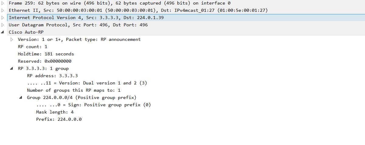
1) RP sends RP-Announce messages to the reserved address - 224.0.1.39, declaring himself an RP either for all or for certain groups. This message is sent every minute.
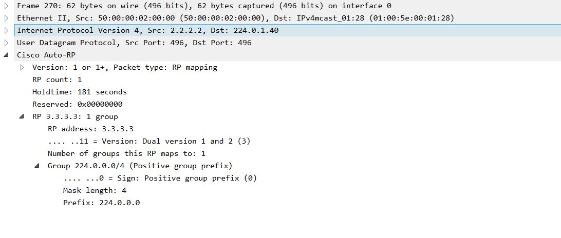
2) An RP mapping agent is needed that will send RP-Discovery messages indicating for which groups which RP to listen to. It is from this message that ordinary PIM routers will determine the RP for themselves. The Mapping Agent can be either the RP router itself or any separate PIM router. RP-Discovery is sent to address 224.0.1.40 with a timer of one minute.
Let's look at the process in more detail:
Set up R3 as RP:
R2 as a mapping agent:
And on all the others, we will expect RP through Auto-RP:
As soon as we configure R3, it will start sending RP-Announce: And R2, after setting up the mapping agent, it will wait for RP-Announce messages. Only when he finds at least one RP, he will start sending RP-Discovery: Thus, as soon as ordinary routers (PIM RP Listener) receive this message, they will know where to look for RP.
One of the main problems of Auto-RP is that in order to receive RP-Announce and RP-Discovery messages, you need to send PIM Join to addresses 224.0.1.39-40, and in order to send, you need to know where the RP is. The classic problem of chicken and eggs. To solve this problem, the PIM Sparse-Dense-Mode was invented. If the router does not know RP, then it works in Dense-mode, if it knows, then in Sparse-mode. When the PIM Sparse-mode and the ip pim autorp listener command are configured on the interfaces of ordinary routers, the router will work in Dense-mode only for the multicast directly Auto-RP protocol (224.0.1.39-40).
BootStrap Router (BSR).
This function works similar to Auto-RP. Each RP sends a mapping agent message, which collects mapping information and then tells all the other routers. We describe the process in the same way as Auto-RP:
1) As soon as we configure R3 as a candidate to be an RP, the command:
That R3 will not do anything, in order to start sending special messages, he, for a start, needs to find a mapping agent. Thus, we pass to the second step.
2) Configure R2 as a mapping agent:
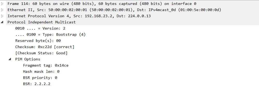
R2 starts sending PIM Bootstrap messages where it identifies itself as a mapping agent: This message is sent to address 224.0.013, which the PIM protocol uses for its other messages. He sends them in all directions and therefore there is no problem of chicken and eggs, as was the case in Auto-RP. 3) As soon as the RP receives a message from the BSR of the router, it will immediately send a unicast message to the address of the BSR of the router: After which, the BSR will receive information about the RP and will send them multicast to the address 224.0.0.13, which all PIM routers listen to. Therefore, there is no analogue of the ip pim autorp listener command for regular routers in BSR. Anycast RP with Multicast Source Discovery Protocol (MSDP).
Auto-RP and BSR allow us to distribute the load on the RP as follows: Each multicast group has only one active RP. It will not work to make a load distribution for one multicast group of several RPs. MSDP does this by issuing RP routers the same ip address with a mask of 255.255.255.255. MSDP recognizes information using one of the methods: static, Auto-RP, or BSR.
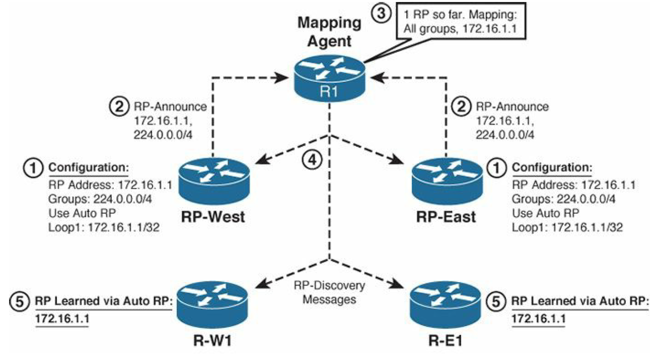
In the picture we have an Auto-RP configuration with MSDP. Both RPs are configured with ip address 172.16.1.1/32 on the Loopback 1 interface and is used for all groups. When RP-Announce, both routers talk about themselves, referring to this address. Auto-RP mapping agent, having received the information, sends RP-Discovery about the RP with the address 172.16.1.1/32. About the network 172.16.1.1/32, we tell routers using IGP and, respectively. Thus, PIM routers request or register flows from the RP indicated as next-hop on the route to the network 172.16.1.1/32. The MSDP protocol itself is intended for the RPs themselves to exchange multicast information messages.
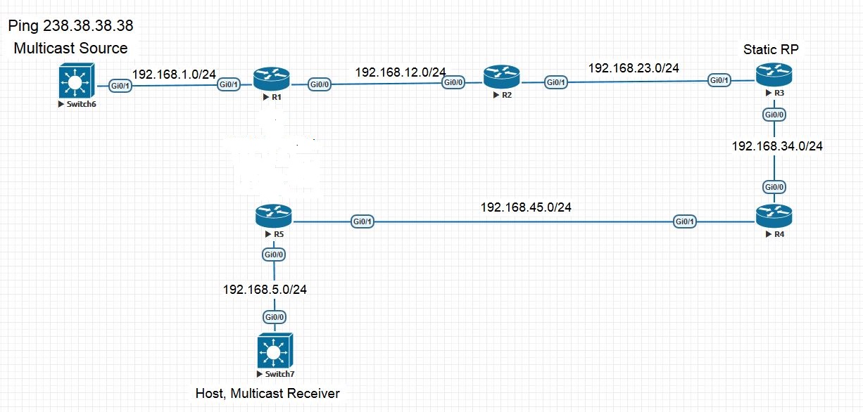
Consider the following topology:
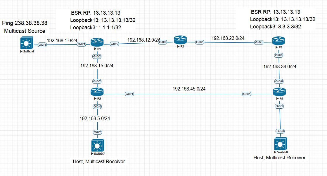
Switch6 broadcasts traffic to the address 238.38.38.38 and so far only RP-R1 knows about it. Here Switch7 and Switch8 requested this group. Routers R5 and R4 will send PIM Join to R1 and R3, respectively. Why? The route until 13.13.13.13 on R5 will refer to R1 according to the IGP metric, as on R4.
RP-R1 knows about the stream and starts broadcasting it in the direction of R5, but R4 does not know anything about it, since R1 just will not send it. Therefore, MSDP is required. We configure it on R1 and R5:
They will raise a session between each other and upon receiving any stream will report it to their RP neighbor.
RP-R1 as soon as it receives the stream from Switch6, it will immediately send Unicast MSDP Source-Active a message that will contain information like (S, G) - information about the source and destination of the multicast. Now, when RP-R3 knows that such a source as Switch6, it will send a PIM Join towards Switch6 when receiving a request from R4 for this stream, guided by the routing table. Therefore, R1 having received such a PIM Join, will begin to send traffic towards RP-R3.
MSDP works over TCP, RP send each other keepalive messages to check the viability. The timer is 60 seconds.
The function of splitting MSDP peers into different domains remains incomprehensible, since the Keepalive and SA messages do not indicate belonging to any domain. Also, in this topology, the configuration was tested with the indication of various domains - there was no difference in operation.
If someone can clarify, I read with pleasure in the comments.
On this I think to finish the article. Below are useful materials and links that were used:

Source-Based Distribution Trees.
It is advisable to use the Dense-mode mode in the case of a large number of clients of various multicast groups. When a router receives multicast traffic, the first thing it does is check it for the RPF rule. RPF - this rule is used to check the source of a multicast with a unicast routing table. It is necessary that the traffic came to the interface behind which this host is hidden according to the version of the unicast routing table. This mechanism solves the problem of loop occurrence during multicast transmission.

R3 from the multicast message recognizes the source of the multicast (Source IP) and checks the two streams from R1 and R2 from its unicast table. The stream from the interface indicated by the table (R1 to R3) will be transmitted further, and the stream from R2 will be dropped, because in order to get to the source of the multicast, it is necessary to send packets via S0 / 1.
The question is, what happens if you have two equivalent routes with the same metric? In this case, the router will choose next-hop for these routes. Who has a higher ip address, he won. If you need to change this behavior, you can use ECMP. More details here .
After checking the RPF rule, the router sends a multicast packet to all its PIM neighbors, except for the one from whom the packet was received. Other PIM routers repeat this process. The path that the multicast packet has passed from the source to the final recipients forms a tree called - source-based distribution tree, shortest-path tree (SPT), source tree. Three different names, choose any.
How to solve the problem with the fact that some routers didn’t give up some multicast stream and there is no one to send it to, and a higher-level router sends it. For this, the Prune mechanism was invented.
Prune Message.
For example, R2 will continue to send R3 multicast, although R3 by the rule of RPF drops it. Why load the channel? R3 sends a PIM Prune Message and R2, upon receiving this message, removes the S0 / 1 interface from the outgoing interface list for this stream, the list of interfaces from which this traffic should be sent.
The following is a more formal definition of a PIM Prune message:
The PIM Prune message is sent by one router to a second router to cause the second router to remove the link on which the Prune is received from a particular (S, G) SPT .
After receiving the Prune message, R2 sets the Prune timer to 3 minutes. After three minutes, it will start sending traffic again until it receives the next Prune message. This is in PIMv1.
And in PIMv2 State Refresh timer is added (by default 60 seconds). As soon as Prune has sent a message with R3, this timer starts on R3. After this timer expires, R3 will send a State Refresh message that will reset the 3-minute Prune Timer to R2 for this group.
Reasons for sending a Prune message:
- When a multicast packet failed an RPF check.
- When there are no locally connected clients that requested a multicast group (IGMP Join) and no PIM neighbors to whom multicast traffic can be sent (Non-prune Interface).
Graft Message.
Imagine that R3 did not want traffic from R2, sent Prune and received multicast from R1. But suddenly, the channel fell between R1-R3 and R3 was left without a multicast. You can wait 3 minutes until Prune Timer expires on R2. 3 minutes to wait a long time, so as not to wait, you need to send a message that instantly displays this interface S0 / 1 on R2 from the pruned state. This message will be a Graft message. After receiving the Graft message, R2 will send a Graft-ACK in response.
Prune Override.

Let's look at this scheme. R1 broadcasts multicast in a segment with two routers. R3 receives and broadcasts traffic, R2 receives, but it has no one to broadcast traffic. It sends a Prune message to R1 in this segment. R1 should remove Fa0 / 0 from the list and stop broadcasting in this segment, but what will happen to R3? And R3 is in the same segment, he also received this message from Prune and realized the tragedy of the situation. Before R1 stops broadcasting, it sets the timer to 3 seconds and stops broadcasting after 3 seconds. 3 seconds - just so much time for R3, so as not to lose your multicast. Therefore, R3, as soon as possible, sends a Pim Join message for this group and R1 no longer thinks to stop broadcasting. About Join posts below.
Assert Message.

Imagine this situation: two routers broadcast to the same network at once. They receive the same stream from the source, and both broadcast it to the same network behind the e0 interface. Therefore, they need to determine who will be the only single broadcaster for this network. Assert messages are used for this. When R2 and R3 detect duplication of multicast traffic, that is, multicast that they broadcast on R2 and R3, which they themselves broadcast, the routers understand that something is wrong here. In this case, the routers send Assert messages, which include the Administrative Distance and the route metric by which the multicast source is reached - 10.1.1.10. The winner is determined as follows:
- The one with lower AD.
- If AD are equal, then who has the lower metric.
- If there is equality, then the one with a higher IP in the network to which they broadcast this multicast.
Winning this vote, the router becomes the Designated Router. Pim Hello is also used to select DR. At the beginning of the article, a PIM Hello message was shown, where you can notice the DR field. The winner is the one with a higher IP address on this link.
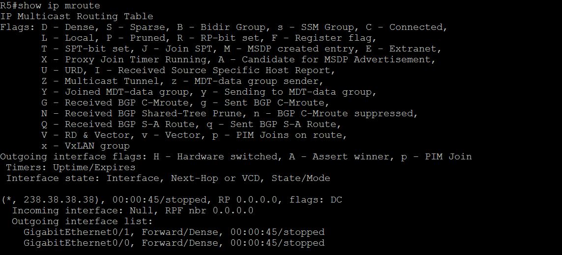
Useful plate: MROUTE Table. After the initial review of the operation of the PIM protocol, we need to figure out how to work with the multicast routing table. The mroute table stores information about which streams were requested by clients and which streams flow from multicast servers. For example, when receiving an IGMP Membership Report or PIM Join on some interface, an entry of the type (*, G) is added to the routing table:


This entry means that a traffic request was received with the address 238.38.38.38. The DC flag means that the multicast will work in Dense mode and C means that the recipient is directly connected to the router, that is, the router received the IGMP Membership Report, and PIM Join.
If there is a record like (S, G) means that we have a multicast stream:

In the S field - 192.168.1.11, we have the IP address of the multicast source registered, it will be checked by the RPF rule. In case of problems, the first thing to do is check the unicast table for the route to the source. In the Incoming Interface field indicates the interface to which the multicast arrives. In the unicast routing table, the route to the source must refer to the interface specified here. The Outgoing Interface indicates where the multicast will be redirected. If it is empty, then there were no requests for this traffic to the router. More information on all flags can be found here .
PIM Sparse-mode.
The Sparse-mode strategy is the opposite of Dense-mode. When Sparse-mode receives multicast traffic, it will send traffic only through those interfaces where there were requests for this stream, for example, Pim Join or IGMP Report messages requesting this traffic.
Similar elements for SM and DM:
- Neighborhood relationships are built in the same way as in PIM DM.
- The RPF rule works.
- The choice of DR is similar.
- The Prune Overrides engine and Assert messages are similar.
To control who needs where, where and what multicast traffic is needed on the network, a common information center is needed. Such a center we will have Rendezvous Point (RP). Anyone who wants some kind of multicast traffic or someone started to receive multicast traffic from the source, then he sends it to the RP.
When the RP receives multicast traffic, it will send it to those routers that previously requested this traffic. Imagine a topology where RP is R3. As soon as R1 receives traffic from S1, it encapsulates this multicast packet in a unicast PIM Register message and sends it to RP. How does he know who is RP? In this case, it is configured statically, and we'll talk about the dynamic tuning of RP later.

ip pim rp-address 3.3.3.3
RP will look - was there any information from someone who would like to receive this traffic? Suppose it was not. Then RP will send R1 a PIM Register-Stop message, which means no one needs this multicast, registration is denied. R1 will not send multicasts. But the multicast source will send it, so R1, after receiving Register-Stop, will start the Register-Suppression timer, which is 60 seconds. 5 seconds before the expiration of this timer, R1 will send an empty Register message with a Null-Register bit (that is, without an encapsulated multicast packet) to the RP side. RP, in turn, will act like this:
- If there were no and no recipients, then it will respond with a Register-Stop message.
- If the recipients appeared, then he will not answer him in any way. R1, having not received a refusal for its registration within 5 seconds, will be delighted and will send Register a message with the encapsulated multicast to RP.
As the multicast reaches the RP, it seems to be sorted out, now let's try to answer the question of how the RP brings traffic to the recipients. Here you need to introduce a new concept - root-path tree (RPT). An RPT is a tree with a root in the RP growing towards the recipients branching on each PIM-SM router. RP creates it by receiving PIM Join messages and adds a new branch to the tree. And so does every downstream router. The general rule looks like this:
- When a PIM-SM router receives a PIM Join message on any interface, except for the interface behind which the RP is hidden, it adds a new branch to the tree.
- A branch is also added when the PIM-SM router receives an IGMP Membership Report from a directly connected host.
Imagine that we have a multicast client on R5 router for group 228.8.8.8. As soon as R5 receives an IGMP Membership Report from the host, R5 sends a PIM Join in the direction of RP, and it itself adds an interface looking at the host into the tree. Next, R4 receives a PIM Join from R5, adds the Gi0 / 1 interface to the tree, and sends the PIM Join in the direction of RP. Finally, RP (R3) receives a PIM Join and adds Gi0 / 0 to the tree. Thus, the registration of the multicast recipient is obtained. We are building a tree with the root R3-Gi0 / 0 → R4-Gi0 / 1 → R5-Gi0 / 0.
After that, PIM Join will be sent to R1 and R1 will start sending multicast traffic. It is important to note that if the host requested traffic before multicast broadcasting began, then the RP will not send PIM Join and will not send anything to the R1 side at all.
If suddenly while a multicast is being sent, the host stops wanting to receive it, as soon as the RP receives PIM Prune on the Gi0 / 0 interface, then it immediately sends the PIM Register-Stop directly to R1, and then the PIM Prune message via the Gi0 / 1 interface. PIM Register-stop is sent by Unicast to the address from which the PIM Register arrived.
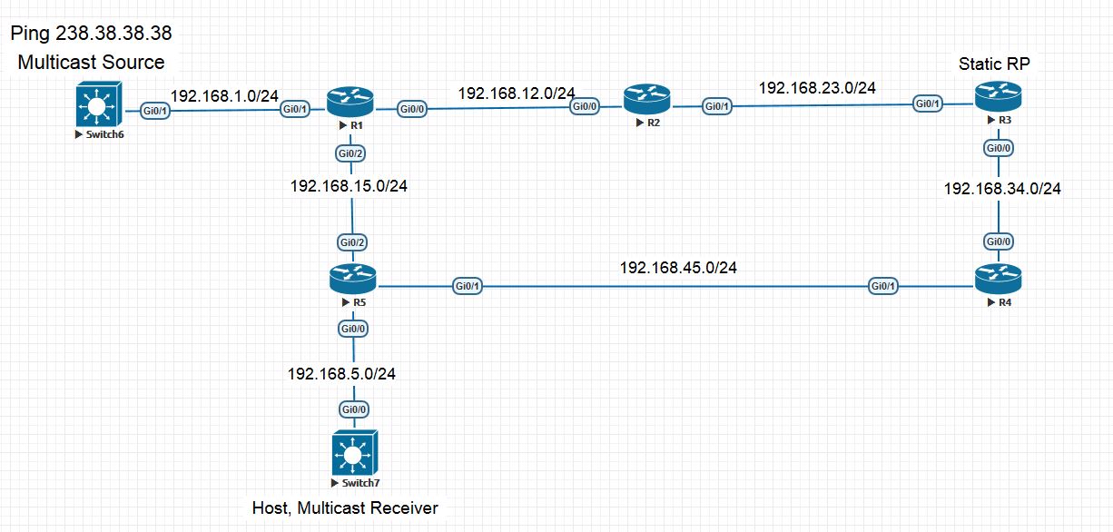
As we said earlier, as soon as the router sends a PIM Join to another one, for example, R5 to R4, then an entry is added to R4: And the timer starts, that reset this timer R5 should constantly PIM Join messages constantly, otherwise R4 will exclude it from the outgoing list. R5 will send every 60 PIM Join messages. Shortest-Path Tree Switchover. We will add an interface between R1 and R5, see how traffic will flow with this topology.


Let's say that the traffic was sent and received according to the old scheme R1-R2-R3-R4-R5 and here we connected and configured the interface between R1 and R5.
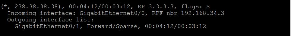
First of all, we have to rebuild the unicast routing table on R5 and now the network 192.168.1.0/24 is reached through the R5 Gi0 / 2 interface. Now, when R5 receives a multicast on the Gi0 / 1 interface, he understands that the RPF rule is not satisfied and it would be more logical to receive a multicast on Gi0 / 2. It should disconnect from the RPT and build a shorter tree called the Shortest-Path Tree (SPT). To do this, he sends PIM Join via Gi0 / 2 to R1 and R1 starts sending multicast via Gi0 / 2 as well. Now R5 must unsubscribe from the RPT, so as not to get two copies. To do this, he sends a Prune message indicating the source ip address and inserting a special bit - RPT-bit. This means that I do not need to send traffic, I have a better tree here. The RP also sends messages to the R1 PIM Prune side, but does not send a Register-Stop message. Another feature: R5 will now constantly send PIM Prune to RP, as R1 continues to send PIM Register to RP every minute. RP until there are new people wishing this traffic will refuse him. R5 notifies the RP that it continues to receive multicast via SPT.
Dynamic RP search.
Auto-RP
This technology is proprietary from Cisco and is not very popular, but still alive. Auto-RP operation consists of two main stages:
1) RP sends RP-Announce messages to the reserved address - 224.0.1.39, declaring himself an RP either for all or for certain groups. This message is sent every minute.
2) An RP mapping agent is needed that will send RP-Discovery messages indicating for which groups which RP to listen to. It is from this message that ordinary PIM routers will determine the RP for themselves. The Mapping Agent can be either the RP router itself or any separate PIM router. RP-Discovery is sent to address 224.0.1.40 with a timer of one minute.
Let's look at the process in more detail:
Set up R3 as RP:
ip pim send-rp-announce loopback 0 scope 10
R2 as a mapping agent:
ip pim send-rp-discovery loopback 0 scope 10
And on all the others, we will expect RP through Auto-RP:
ip pim autorp listener
As soon as we configure R3, it will start sending RP-Announce: And R2, after setting up the mapping agent, it will wait for RP-Announce messages. Only when he finds at least one RP, he will start sending RP-Discovery: Thus, as soon as ordinary routers (PIM RP Listener) receive this message, they will know where to look for RP.


One of the main problems of Auto-RP is that in order to receive RP-Announce and RP-Discovery messages, you need to send PIM Join to addresses 224.0.1.39-40, and in order to send, you need to know where the RP is. The classic problem of chicken and eggs. To solve this problem, the PIM Sparse-Dense-Mode was invented. If the router does not know RP, then it works in Dense-mode, if it knows, then in Sparse-mode. When the PIM Sparse-mode and the ip pim autorp listener command are configured on the interfaces of ordinary routers, the router will work in Dense-mode only for the multicast directly Auto-RP protocol (224.0.1.39-40).
BootStrap Router (BSR).
This function works similar to Auto-RP. Each RP sends a mapping agent message, which collects mapping information and then tells all the other routers. We describe the process in the same way as Auto-RP:
1) As soon as we configure R3 as a candidate to be an RP, the command:
ip pim rp-candidate loopback 0
That R3 will not do anything, in order to start sending special messages, he, for a start, needs to find a mapping agent. Thus, we pass to the second step.
2) Configure R2 as a mapping agent:
ip pim bsr-candidate loopback 0
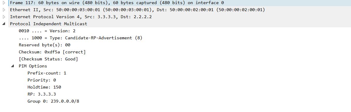
R2 starts sending PIM Bootstrap messages where it identifies itself as a mapping agent: This message is sent to address 224.0.013, which the PIM protocol uses for its other messages. He sends them in all directions and therefore there is no problem of chicken and eggs, as was the case in Auto-RP. 3) As soon as the RP receives a message from the BSR of the router, it will immediately send a unicast message to the address of the BSR of the router: After which, the BSR will receive information about the RP and will send them multicast to the address 224.0.0.13, which all PIM routers listen to. Therefore, there is no analogue of the ip pim autorp listener command for regular routers in BSR. Anycast RP with Multicast Source Discovery Protocol (MSDP).


Auto-RP and BSR allow us to distribute the load on the RP as follows: Each multicast group has only one active RP. It will not work to make a load distribution for one multicast group of several RPs. MSDP does this by issuing RP routers the same ip address with a mask of 255.255.255.255. MSDP recognizes information using one of the methods: static, Auto-RP, or BSR.

In the picture we have an Auto-RP configuration with MSDP. Both RPs are configured with ip address 172.16.1.1/32 on the Loopback 1 interface and is used for all groups. When RP-Announce, both routers talk about themselves, referring to this address. Auto-RP mapping agent, having received the information, sends RP-Discovery about the RP with the address 172.16.1.1/32. About the network 172.16.1.1/32, we tell routers using IGP and, respectively. Thus, PIM routers request or register flows from the RP indicated as next-hop on the route to the network 172.16.1.1/32. The MSDP protocol itself is intended for the RPs themselves to exchange multicast information messages.
Consider the following topology:

Switch6 broadcasts traffic to the address 238.38.38.38 and so far only RP-R1 knows about it. Here Switch7 and Switch8 requested this group. Routers R5 and R4 will send PIM Join to R1 and R3, respectively. Why? The route until 13.13.13.13 on R5 will refer to R1 according to the IGP metric, as on R4.
RP-R1 knows about the stream and starts broadcasting it in the direction of R5, but R4 does not know anything about it, since R1 just will not send it. Therefore, MSDP is required. We configure it on R1 and R5:
ip msdp peer 3.3.3.3 connect-source Loopback1 on R1
ip msdp peer 1.1.1.1 connect-source Loopback3 on R3
They will raise a session between each other and upon receiving any stream will report it to their RP neighbor.
RP-R1 as soon as it receives the stream from Switch6, it will immediately send Unicast MSDP Source-Active a message that will contain information like (S, G) - information about the source and destination of the multicast. Now, when RP-R3 knows that such a source as Switch6, it will send a PIM Join towards Switch6 when receiving a request from R4 for this stream, guided by the routing table. Therefore, R1 having received such a PIM Join, will begin to send traffic towards RP-R3.
MSDP works over TCP, RP send each other keepalive messages to check the viability. The timer is 60 seconds.
The function of splitting MSDP peers into different domains remains incomprehensible, since the Keepalive and SA messages do not indicate belonging to any domain. Also, in this topology, the configuration was tested with the indication of various domains - there was no difference in operation.
If someone can clarify, I read with pleasure in the comments.
On this I think to finish the article. Below are useful materials and links that were used:
- CCIE Routing and Switching v5.0 Official Cert Guide, Volume 2, Fifth Edition, Narbik Kocharians, Terry Vinson.
- Networks for the smallest. Part Nine. Multicast