How the rendering of The Witcher 3 is implemented: lightning, the witcher's flair, and other effects
- Transfer

Part 1. Zippers
In this part, we will look at the process of rendering lightning in Witcher 3: Wild Hunt.
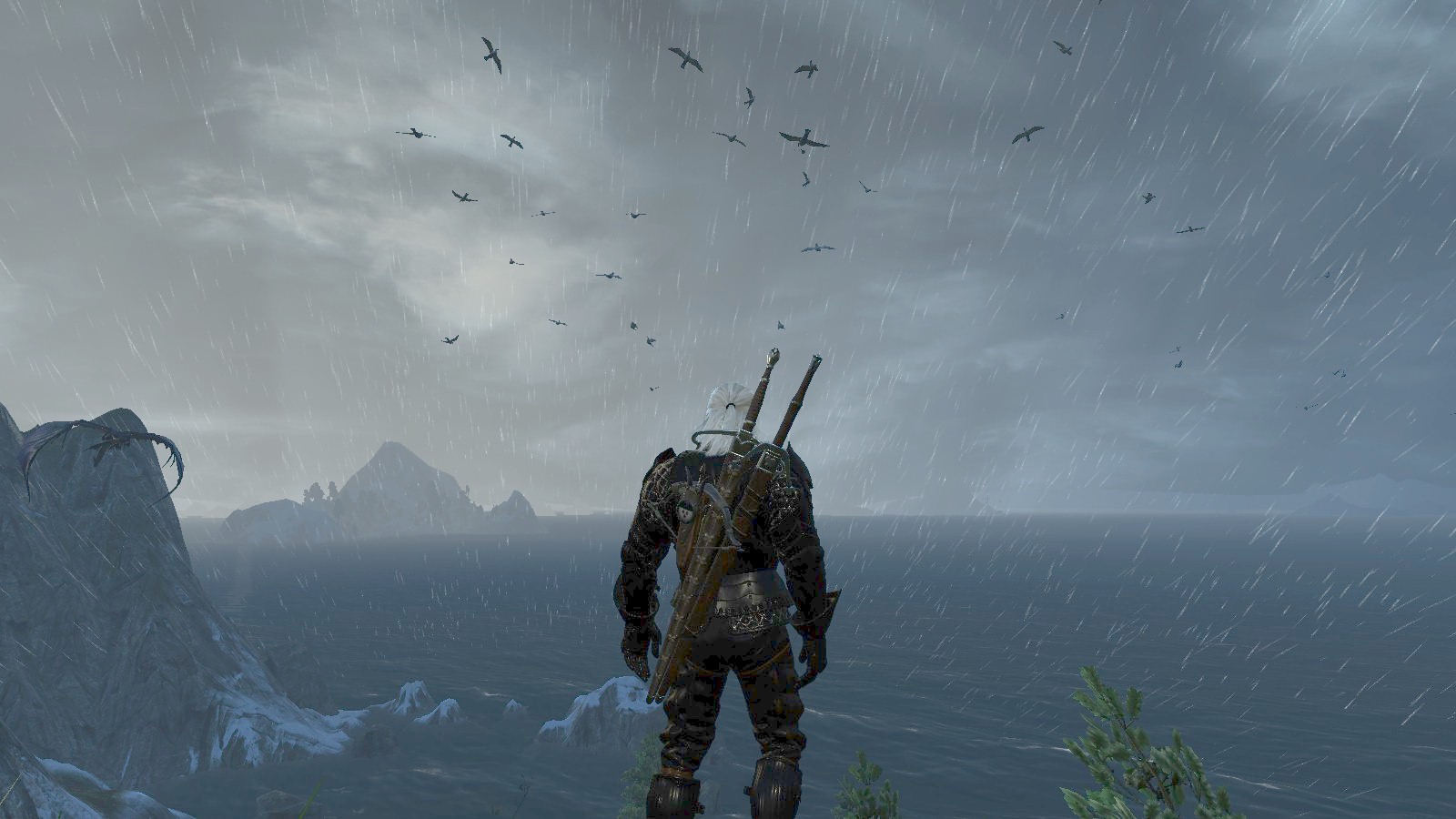
The lightning rendering is performed a little later than the rain curtain effect , but still occurs in the direct rendering pass. Lightning can be seen in this video:
They disappear very quickly, so it’s better to watch the video at a speed of 0.25.
You can see that these are not static images; over time, their brightness changes slightly.
From the point of view of rendering nuances, there are many similarities with drawing a curtain of rain in the distance, for example, the same state of mixing (additive mixing) and depth (checking is enabled, depth recording is not performed).
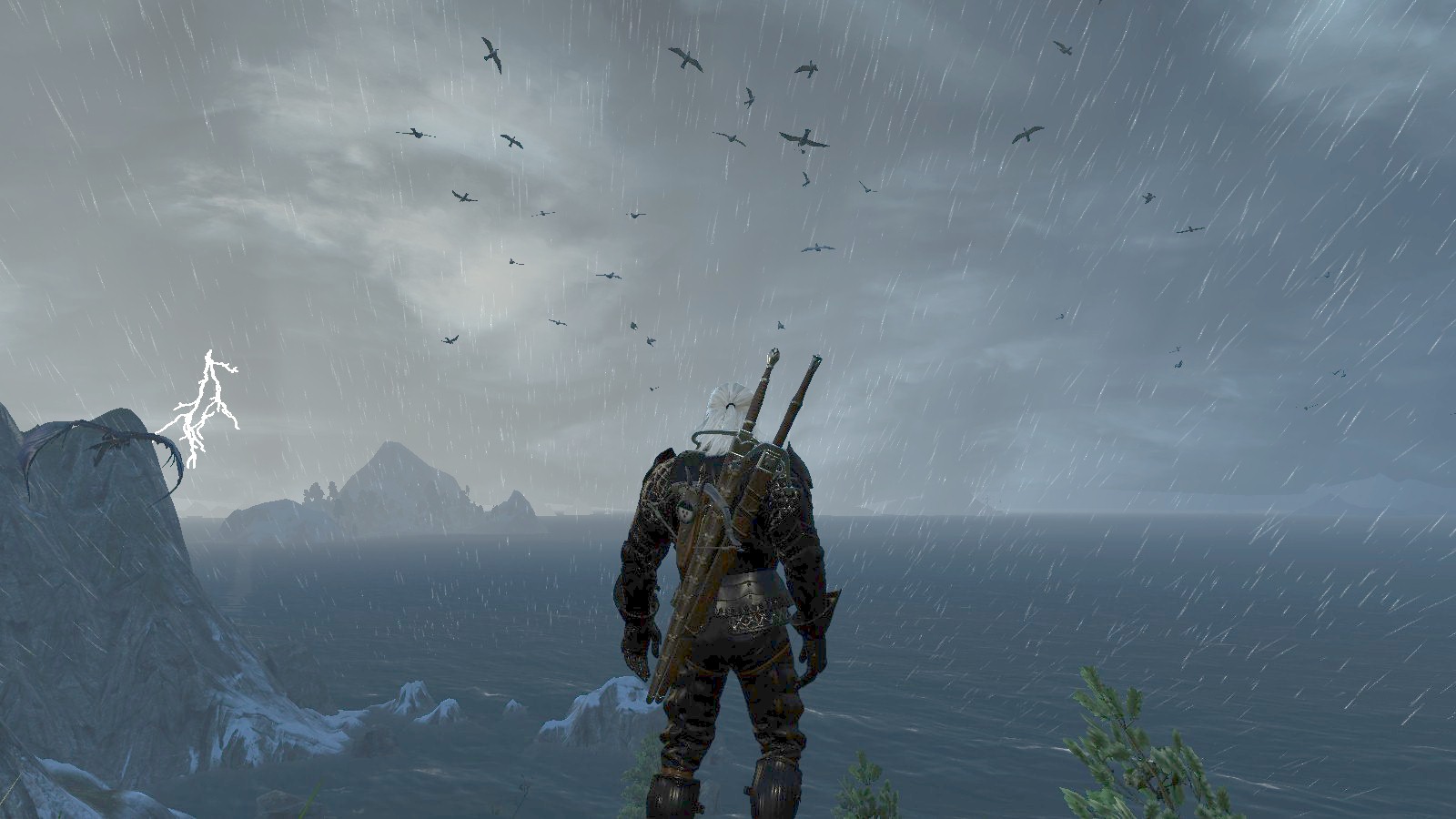
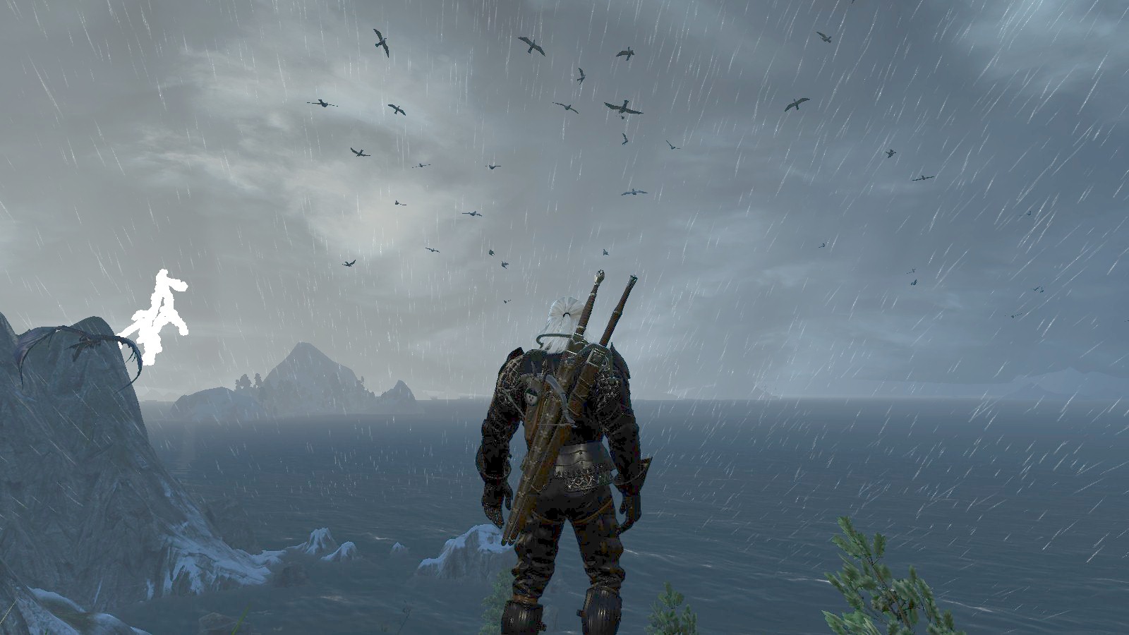
Scene without lightning

The scene with lightning
From the point of view of the geometry of lightning in The Witcher 3 is a tree-like mesh. This example of lightning is represented by the following mesh:
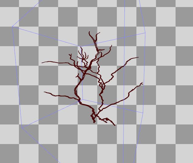
It has UV coordinates and normal vectors. All this comes in handy at the vertex shader stage.
Vertex shader
Let's take a look at the assembled vertex shader code:
 vs_5_0
    dcl_globalFlags refactoringAllowed
    dcl_constantbuffer cb1[9], immediateIndexed
    dcl_constantbuffer cb2[6], immediateIndexed
    dcl_input v0.xyz
    dcl_input v1.xy
    dcl_input v2.xyz
    dcl_input v4.xyzw
    dcl_input v5.xyzw
    dcl_input v6.xyzw
    dcl_input v7.xyzw
    dcl_output o0.xy
    dcl_output o1.xyzw
    dcl_output_siv o2.xyzw, position
    dcl_temps 3
   0: mov o0.xy, v1.xyxx
   1: mov o1.xyzw, v7.xyzw
   2: mul r0.xyzw, v5.xyzw, cb1[0].yyyy
   3: mad r0.xyzw, v4.xyzw, cb1[0].xxxx, r0.xyzw
   4: mad r0.xyzw, v6.xyzw, cb1[0].zzzz, r0.xyzw
   5: mad r0.xyzw, cb1[0].wwww, l(0.000000, 0.000000, 0.000000, 1.000000), r0.xyzw
   6: mov r1.w, l(1.000000)
   7: mad r1.xyz, v0.xyzx, cb2[4].xyzx, cb2[5].xyzx
   8: dp4 r2.x, r1.xyzw, v4.xyzw
   9: dp4 r2.y, r1.xyzw, v5.xyzw
  10: dp4 r2.z, r1.xyzw, v6.xyzw
  11: add r2.xyz, r2.xyzx, -cb1[8].xyzx
  12: dp3 r1.w, r2.xyzx, r2.xyzx
  13: rsq r1.w, r1.w
  14: div r1.w, l(1.000000, 1.000000, 1.000000, 1.000000), r1.w
  15: mul r1.w, r1.w, l(0.000001)
  16: mad r2.xyz, v2.xyzx, l(2.000000, 2.000000, 2.000000, 0.000000), l(-1.000000, -1.000000, -1.000000, 0.000000)
  17: mad r1.xyz, r2.xyzx, r1.wwww, r1.xyzx
  18: mov r1.w, l(1.000000)
  19: dp4 o2.x, r1.xyzw, r0.xyzw
  20: mul r0.xyzw, v5.xyzw, cb1[1].yyyy
  21: mad r0.xyzw, v4.xyzw, cb1[1].xxxx, r0.xyzw
  22: mad r0.xyzw, v6.xyzw, cb1[1].zzzz, r0.xyzw
  23: mad r0.xyzw, cb1[1].wwww, l(0.000000, 0.000000, 0.000000, 1.000000), r0.xyzw
  24: dp4 o2.y, r1.xyzw, r0.xyzw
  25: mul r0.xyzw, v5.xyzw, cb1[2].yyyy
  26: mad r0.xyzw, v4.xyzw, cb1[2].xxxx, r0.xyzw
  27: mad r0.xyzw, v6.xyzw, cb1[2].zzzz, r0.xyzw
  28: mad r0.xyzw, cb1[2].wwww, l(0.000000, 0.000000, 0.000000, 1.000000), r0.xyzw
  29: dp4 o2.z, r1.xyzw, r0.xyzw
  30: mul r0.xyzw, v5.xyzw, cb1[3].yyyy
  31: mad r0.xyzw, v4.xyzw, cb1[3].xxxx, r0.xyzw
  32: mad r0.xyzw, v6.xyzw, cb1[3].zzzz, r0.xyzw
  33: mad r0.xyzw, cb1[3].wwww, l(0.000000, 0.000000, 0.000000, 1.000000), r0.xyzw
  34: dp4 o2.w, r1.xyzw, r0.xyzw
  35: ret
There are many similarities with the vertex shader rain curtain, so I will not repeat. I want to show you the important difference that is in lines 11-18:
  11: add r2.xyz, r2.xyzx, -cb1[8].xyzx
  12: dp3 r1.w, r2.xyzx, r2.xyzx
  13: rsq r1.w, r1.w
  14: div r1.w, l(1.000000, 1.000000, 1.000000, 1.000000), r1.w
  15: mul r1.w, r1.w, l(0.000001)
  16: mad r2.xyz, v2.xyzx, l(2.000000, 2.000000, 2.000000, 0.000000), l(-1.000000, -1.000000, -1.000000, 0.000000)
  17: mad r1.xyz, r2.xyzx, r1.wwww, r1.xyzx
  18: mov r1.w, l(1.000000)
  19: dp4 o2.x, r1.xyzw, r0.xyzw
Firstly, cb1 [8] .xyz is the position of the camera, and r2.xyz is the position in world space, that is, line 11 calculates the vector from the camera to the position in the world. Then lines 12-15 calculate length (worldPos - cameraPos) * 0.000001.
v2.xyz is the normal vector of the incoming geometry. Line 16 extends it from the interval [0-1] to the interval [-1; 1].
Then the final position in the world is calculated:
finalWorldPos = worldPos + length (worldPos - cameraPos) * 0.000001 * normalVector
The HLSL code snippet for this operation will look something like this:
      ...
      // final world-space position
      float3 vNormal = Input.NormalW * 2.0 - 1.0;
      float lencameratoworld = length( PositionL - g_cameraPos.xyz) * 0.000001;
      PositionL += vNormal*lencameratoworld;
      // SV_Posiiton
      float4x4 matModelViewProjection = mul(g_viewProjMatrix, matInstanceWorld );
      Output.PositionH = mul( float4(PositionL, 1.0), transpose(matModelViewProjection) );
      return Output;
This operation results in a small “burst” of the mesh (in the direction of the normal vector). I experimented by replacing 0.000001 with several other values. Here are the results:

0.000002
0.000005

0.00001
0.000025
Pixel shader
Well, we figured out the vertex shader, now it's time to get down to the assembler code for the pixel shader!
 ps_5_0
    dcl_globalFlags refactoringAllowed
    dcl_constantbuffer cb0[1], immediateIndexed
    dcl_constantbuffer cb2[3], immediateIndexed
    dcl_constantbuffer cb4[5], immediateIndexed
    dcl_input_ps linear v0.x
    dcl_input_ps linear v1.w
    dcl_output o0.xyzw
    dcl_temps 1
   0: mad r0.x, cb0[0].x, cb4[4].x, v0.x
   1: add r0.y, r0.x, l(-1.000000)
   2: round_ni r0.y, r0.y
   3: ishr r0.z, r0.y, l(13)
   4: xor r0.y, r0.y, r0.z
   5: imul null, r0.z, r0.y, r0.y
   6: imad r0.z, r0.z, l(0x0000ec4d), l(0.0000000000000000000000000000000000001)
   7: imad r0.y, r0.y, r0.z, l(146956042240.000000)
   8: and r0.y, r0.y, l(0x7fffffff)
   9: round_ni r0.z, r0.x
  10: frc r0.x, r0.x
  11: add r0.x, -r0.x, l(1.000000)
  12: ishr r0.w, r0.z, l(13)
  13: xor r0.z, r0.z, r0.w
  14: imul null, r0.w, r0.z, r0.z
  15: imad r0.w, r0.w, l(0x0000ec4d), l(0.0000000000000000000000000000000000001)
  16: imad r0.z, r0.z, r0.w, l(146956042240.000000)
  17: and r0.z, r0.z, l(0x7fffffff)
  18: itof r0.yz, r0.yyzy
  19: mul r0.z, r0.z, l(0.000000001)
  20: mad r0.y, r0.y, l(0.000000001), -r0.z
  21: mul r0.w, r0.x, r0.x
  22: mul r0.x, r0.x, r0.w
  23: mul r0.w, r0.w, l(3.000000)
  24: mad r0.x, r0.x, l(-2.000000), r0.w
  25: mad r0.x, r0.x, r0.y, r0.z
  26: add r0.y, -cb4[2].x, cb4[3].x
  27: mad_sat r0.x, r0.x, r0.y, cb4[2].x
  28: mul r0.x, r0.x, v1.w
  29: mul r0.yzw, cb4[0].xxxx, cb4[1].xxyz
  30: mul r0.xyzw, r0.xyzw, cb2[2].wxyz
  31: mul o0.xyz, r0.xxxx, r0.yzwy
  32: mov o0.w, r0.x
  33: ret
Good news: the code is not so long.
Bad news:
   3: ishr r0.z, r0.y, l(13)
   4: xor r0.y, r0.y, r0.z
   5: imul null, r0.z, r0.y, r0.y
   6: imad r0.z, r0.z, l(0x0000ec4d), l(0.0000000000000000000000000000000000001)
   7: imad r0.y, r0.y, r0.z, l(146956042240.000000)
   8: and r0.y, r0.y, l(0x7fffffff)
... what is it all about?
Honestly, this is not the first time I've seen such a piece ... of assembler code in the Witcher 3 shaders. But when I first met him, I thought: “What the hell is this?”
Something similar can be found in some other TW3 shaders. I will not describe my adventures with this fragment, and just say that the answer lies in integer noise :
 // For more details see: http://libnoise.sourceforge.net/noisegen/
 float integerNoise( int n )
 {
      n = (n >> 13) ^ n;
      int nn = (n * (n * n * 60493 + 19990303) + 1376312589) & 0x7fffffff;
      return ((float)nn / 1073741824.0);
 }
As you can see, in the pixel shader it is called twice. Using the guides from this website, we can understand how smooth noise is correctly implemented. I will come back to this in a minute.
Look at line 0 - here we are doing the animation based on the following formula:
animation = elapsedTime * animationSpeed + TextureUV.x
These values, after rounding down ( floor ) ( round_ni instruction ) later become input points for integer noise. Usually we calculate the noise value for two integers, and then we calculate the final, interpolated value between them (see the libnoise website for details).
Okay that's integernoise, but after all all the previously mentioned values (also rounded down) are float!
Note that there are no ftoi instructions here . I assume that the programmers at CD Projekt Red have used the HLSL asint internal function here , which performs the conversion of “reinterpret_cast” floating point values and treats them as an integer pattern.
The interpolation weight for two values is calculated in lines 10-11
interpolationWeight = 1.0 - frac (animation);
This approach allows us to interpolate between values over time.
To create smooth noise, this interpolator is passed to the SCurve function :
 float s_curve( float x )
 {
   float x2 = x * x;
   float x3 = x2 * x;
   // -2x^3 + 3x^2
   return -2.0*x3 + 3.0*x2;
 }
Smoothstep Function [libnoise.sourceforge.net]
This function is known as “smoothstep”. But as you can see from the assembler code, this is not an internal smoothstep function from HLSL. An internal function applies restrictions so that the values are true. But since we know that interpolationWeight will always be in the range [0-1], these checks can be safely skipped.
When calculating the final value, several multiplication operations are used. See how the final alpha output can change depending on the noise value. This is convenient because it will affect the opacity of the rendered lightning, just like in real life.
Ready pixel shader:
 cbuffer cbPerFrame : register (b0)
 {
   float4 cb0_v0;
   float4 cb0_v1;
   float4 cb0_v2;
   float4 cb0_v3;
 }
 cbuffer cbPerFrame : register (b2)
 {
   float4 cb2_v0;
   float4 cb2_v1;
   float4 cb2_v2;
   float4 cb2_v3;
 }
 cbuffer cbPerFrame : register (b4)
 {
   float4 cb4_v0;
   float4 cb4_v1;
   float4 cb4_v2;
   float4 cb4_v3;
   float4 cb4_v4;
 }
 struct VS_OUTPUT
 {
   float2 Texcoords : Texcoord0;
   float4 InstanceLODParams : INSTANCE_LOD_PARAMS;
   float4 PositionH : SV_Position;
 };
 // Shaders in TW3 use integer noise.
 // For more details see: http://libnoise.sourceforge.net/noisegen/
 float integerNoise( int n )
 {
   n = (n >> 13) ^ n;
   int nn = (n * (n * n * 60493 + 19990303) + 1376312589) & 0x7fffffff;
   return ((float)nn / 1073741824.0);
 }
 float s_curve( float x )
 {
   float x2 = x * x;
   float x3 = x2 * x;
   // -2x^3 + 3x^2
   return -2.0*x3 + 3.0*x2;
 }
 float4 Lightning_TW3_PS( in VS_OUTPUT Input ) : SV_Target
 {
   // * Inputs
   float elapsedTime = cb0_v0.x;
   float animationSpeed = cb4_v4.x;
   float minAmount = cb4_v2.x;
   float maxAmount = cb4_v3.x;
   float colorMultiplier = cb4_v0.x;
   float3 colorFilter = cb4_v1.xyz;
   float3 lightningColorRGB = cb2_v2.rgb;
   // Animation using time and X texcoord
   float animation = elapsedTime * animationSpeed + Input.Texcoords.x;
   // Input parameters for Integer Noise.
   // They are floored and please note there are using asint.
   // That might be an optimization to avoid "ftoi" instructions.
   int intX0 = asint( floor(animation) );
   int intX1 = asint( floor(animation-1.0) );
   float n0 = integerNoise( intX0 );
   float n1 = integerNoise( intX1 );
   // We interpolate "backwards" here.
   float weight = 1.0 - frac(animation);
   // Following the instructions from libnoise, we perform
   // smooth interpolation here with cubic s-curve function.
   float noise = lerp( n0, n1, s_curve(weight) );
   // Make sure we are in [0.0 - 1.0] range.
   float lightningAmount = saturate( lerp(minAmount, maxAmount, noise) );
   lightningAmount *= Input.InstanceLODParams.w;    // 1.0
   lightningAmount *= cb2_v2.w;             // 1.0
   // Calculate final lightning color
   float3 lightningColor = colorMultiplier * colorFilter;
   lightningColor *= lighntingColorRGB;
   float3 finalLightningColor = lightningColor * lightningAmount;
   return float4( finalLightningColor, lightningAmount );
 }
Summarize
In this part, I described a way to render lightning in The Witcher 3.
I am very pleased that the assembler code that came out of my shader completely matches the original!
Part 2. Silly Sky Tricks
This part will be slightly different from the previous ones. In it, I want to show you some aspects of the Witcher 3 sky shader.
Why are “silly tricks” and not the whole shader? Well, there are several reasons. Firstly, the Witcher 3 sky shader is a rather complex beast. The pixel shader from the 2015 version contains 267 lines of assembler code, and the shader from the Blood and Wine DLC contains 385 lines.
Moreover, they receive a lot of input, which is not very conducive to reverse engineering the full (and readable!) HLSL code.
Therefore, I decided to show only part of the tricks from these shaders. If I find something new, I will supplement the post.
The differences between the 2015 version and the DLC (2016) are very noticeable. In particular, they include differences in the calculation of stars and their flicker, a different approach to rendering the Sun ... The Blood and Wine shader even calculates the Milky Way at night.
I'll start with the basics and then talk about stupid tricks.
The basics
Like most modern games, Witcher 3 uses skydome to model the sky. Look at the hemisphere used for this in Witcher 3 (2015). Note: in this case, the bounding box of this mesh is in the range from [0,0,0] to [1,1,1] (Z is the axis pointing up) and has smoothly distributed UVs. Later we use them.
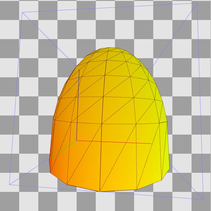
The idea behind skydome is similar to the idea of skybox (the only difference is the mesh used). At the vertex shader stage, we transform the skydome relative to the observer (usually in accordance with the camera position), which creates the illusion that the sky is really very far away - we will never get to it.
If you read the previous parts of this series of articles, then you know that the “The Witcher 3” uses the inverse depth, that is, the far plane is 0.0f, and the nearest is 1.0f. In order for the skydome output to be entirely executed on the far plane, in the parameters of the browse window we set MinDepth to the same value as MaxDepth :
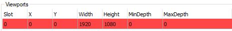
To learn how the MinDepth and MaxDepth fields are used during the conversion of the browse window, click here (docs.microsoft.com).
Vertex shader
Let's start with the vertex shader. In Witcher 3 (2015), the assembler shader code is as follows:
 vs_5_0
    dcl_globalFlags refactoringAllowed
    dcl_constantbuffer cb1[4], immediateIndexed
    dcl_constantbuffer cb2[6], immediateIndexed
    dcl_input v0.xyz
    dcl_input v1.xy
    dcl_output o0.xy
    dcl_output o1.xyz
    dcl_output_siv o2.xyzw, position
    dcl_temps 2
   0: mov o0.xy, v1.xyxx
   1: mad r0.xyz, v0.xyzx, cb2[4].xyzx, cb2[5].xyzx
   2: mov r0.w, l(1.000000)
   3: dp4 o1.x, r0.xyzw, cb2[0].xyzw
   4: dp4 o1.y, r0.xyzw, cb2[1].xyzw
   5: dp4 o1.z, r0.xyzw, cb2[2].xyzw
   6: mul r1.xyzw, cb1[0].yyyy, cb2[1].xyzw
   7: mad r1.xyzw, cb2[0].xyzw, cb1[0].xxxx, r1.xyzw
   8: mad r1.xyzw, cb2[2].xyzw, cb1[0].zzzz, r1.xyzw
   9: mad r1.xyzw, cb1[0].wwww, l(0.000000, 0.000000, 0.000000, 1.000000), r1.xyzw
  10: dp4 o2.x, r0.xyzw, r1.xyzw
  11: mul r1.xyzw, cb1[1].yyyy, cb2[1].xyzw
  12: mad r1.xyzw, cb2[0].xyzw, cb1[1].xxxx, r1.xyzw
  13: mad r1.xyzw, cb2[2].xyzw, cb1[1].zzzz, r1.xyzw
  14: mad r1.xyzw, cb1[1].wwww, l(0.000000, 0.000000, 0.000000, 1.000000), r1.xyzw
  15: dp4 o2.y, r0.xyzw, r1.xyzw
  16: mul r1.xyzw, cb1[2].yyyy, cb2[1].xyzw
  17: mad r1.xyzw, cb2[0].xyzw, cb1[2].xxxx, r1.xyzw
  18: mad r1.xyzw, cb2[2].xyzw, cb1[2].zzzz, r1.xyzw
  19: mad r1.xyzw, cb1[2].wwww, l(0.000000, 0.000000, 0.000000, 1.000000), r1.xyzw
  20: dp4 o2.z, r0.xyzw, r1.xyzw
  21: mul r1.xyzw, cb1[3].yyyy, cb2[1].xyzw
  22: mad r1.xyzw, cb2[0].xyzw, cb1[3].xxxx, r1.xyzw
  23: mad r1.xyzw, cb2[2].xyzw, cb1[3].zzzz, r1.xyzw
  24: mad r1.xyzw, cb1[3].wwww, l(0.000000, 0.000000, 0.000000, 1.000000), r1.xyzw
  25: dp4 o2.w, r0.xyzw, r1.xyzw
  26: ret
In this case, the vertex shader transfers only texcoords and a position in the world space to the output. In Blood and Wine, he also displays a normalized normal vector. I will consider the 2015 version because it is simpler.
Look at the constant buffer designated as cb2 :
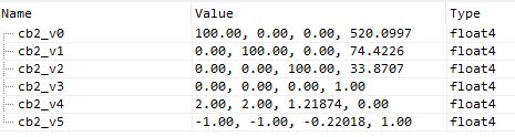
Here we have a matrix of the world (uniform scaling by 100 and transfer relative to the camera position). Nothing complicated. cb2_v4 and cb2_v5 are the scale / deviation factors used to convert vertex positions from the interval [0-1] to the interval [-1; 1]. But here, these coefficients “compress” the Z axis (upward).

In the previous parts of the series, we had similar vertex shaders. The general algorithm is to transfer texcoords further, then Position is calculated taking into account scale / deviation coefficients, then PositionW is calculated in world space, then the final position of the clipping space is calculated by multiplying matWorld and matViewProj -> their product is used to multiply by Position to get the final SV_Position .
Therefore, the HLSL of this vertex shader should be something like this:
struct InputStruct {
float3 param0 : POSITION;
float2 param1 : TEXCOORD;
float3 param2 : NORMAL;
float4 param3 : TANGENT;
};
struct OutputStruct {
float2 param0 : TEXCOORD0;
float3 param1 : TEXCOORD1;
float4 param2 : SV_Position;
};
OutputStruct EditedShaderVS(in InputStruct IN)
{
OutputStruct OUT = (OutputStruct)0;
// Simple texcoords passing
OUT.param0 = IN.param1;
// * Manually construct world and viewProj martices from float4s:
row_major matrix matWorld = matrix(cb2_v0, cb2_v1, cb2_v2, float4(0,0,0,1) );
matrix matViewProj = matrix(cb1_v0, cb1_v1, cb1_v2, cb1_v3);
// * Some optional fun with worldMatrix
// a) Scale
//matWorld._11 = matWorld._22 = matWorld._33 = 0.225f;
// b) Translate
// X Y Z
//matWorld._14 = 520.0997;
//matWorld._24 = 74.4226;
//matWorld._34 = 113.9;
// Local space - note the scale+bias here!
//float3 meshScale = float3(2.0, 2.0, 2.0);
//float3 meshBias = float3(-1.0, -1.0, -0.4);
float3 meshScale = cb2_v4.xyz;
float3 meshBias = cb2_v5.xyz;
float3 Position = IN.param0 * meshScale + meshBias;
// World space
float4 PositionW = mul(float4(Position, 1.0), transpose(matWorld) );
OUT.param1 = PositionW.xyz;
// Clip space - original approach from The Witcher 3
matrix matWorldViewProj = mul(matViewProj, matWorld);
OUT.param2 = mul( float4(Position, 1.0), transpose(matWorldViewProj) );
return OUT;
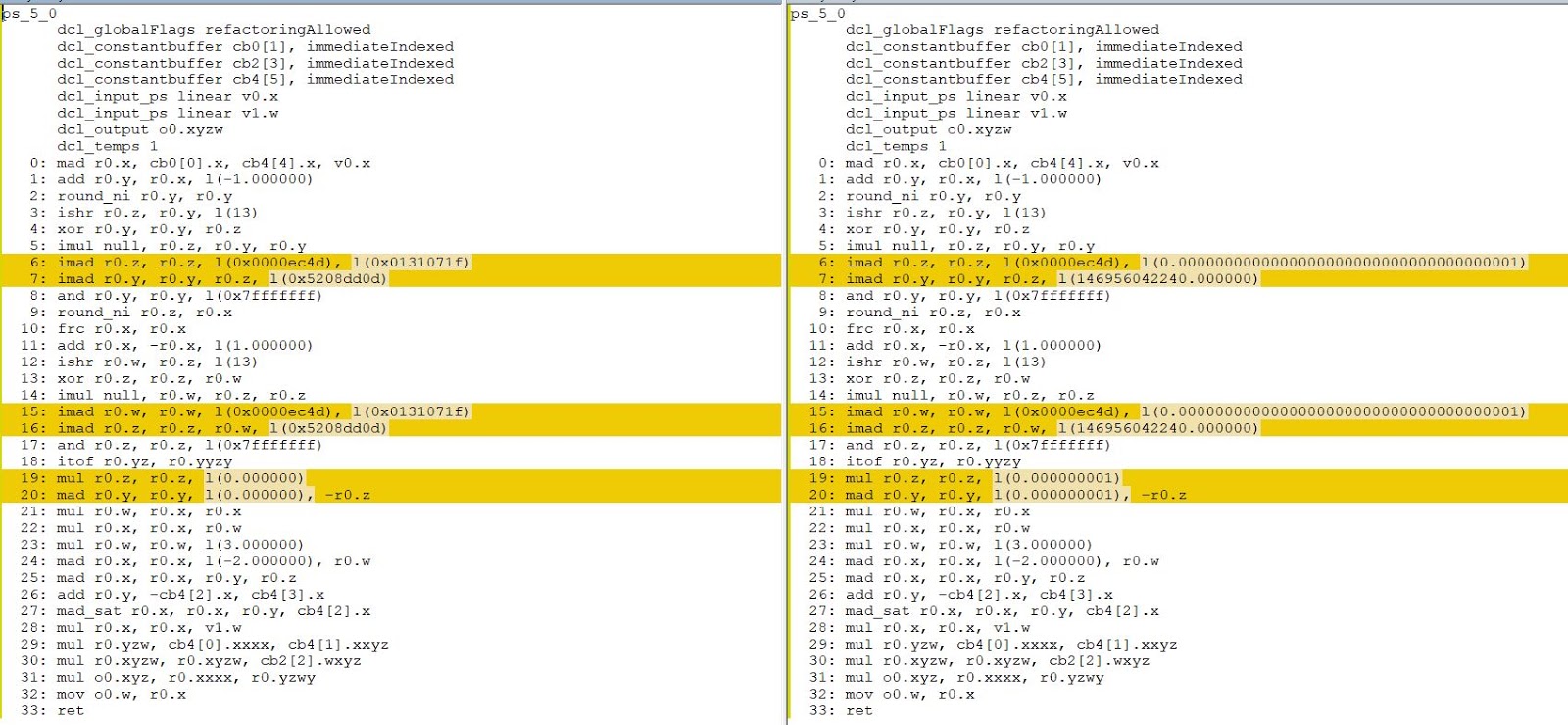
}Comparison of my shader (left) and the original (right):

An excellent property of RenderDoc is that it allows us to inject our own shader instead of the original one, and these changes will affect the pipeline to the very end of the frame. As you can see from the HLSL code, I have provided several options for zooming and transforming the final geometry. You can experiment with them and get very funny results:

Vertex Shader Optimization
Did you notice the problem of the original vertex shader? The vertex multiplication of a matrix by a matrix is completely redundant! I found this in at least a few vertex shaders (for example, in the shader a curtain of rain in the distance ). We can optimize it by immediately multiplying PositionW by matViewProj !
So, we can replace this code with HLSL:
      // Clip space - original approach from The Witcher 3
      matrix matWorldViewProj = mul(matViewProj, matWorld);
      OUT.param2 = mul( float4(Position, 1.0), transpose(matWorldViewProj) );
as follows:
      // Clip space - optimized version
      OUT.param2 = mul( matViewProj, PositionW );
The optimized version gives us the following assembly code:
    vs_5_0
    dcl_globalFlags refactoringAllowed
    dcl_constantbuffer CB1[4], immediateIndexed
    dcl_constantbuffer CB2[6], immediateIndexed
    dcl_input v0.xyz
    dcl_input v1.xy
    dcl_output o0.xy
    dcl_output o1.xyz
    dcl_output_siv o2.xyzw, position
    dcl_temps 2
   0: mov o0.xy, v1.xyxx
   1: mad r0.xyz, v0.xyzx, cb2[4].xyzx, cb2[5].xyzx
   2: mov r0.w, l(1.000000)
   3: dp4 r1.x, r0.xyzw, cb2[0].xyzw
   4: dp4 r1.y, r0.xyzw, cb2[1].xyzw
   5: dp4 r1.z, r0.xyzw, cb2[2].xyzw
   6: mov o1.xyz, r1.xyzx
   7: mov r1.w, l(1.000000)
   8: dp4 o2.x, cb1[0].xyzw, r1.xyzw
   9: dp4 o2.y, cb1[1].xyzw, r1.xyzw
  10: dp4 o2.z, cb1[2].xyzw, r1.xyzw
  11: dp4 o2.w, cb1[3].xyzw, r1.xyzw
  12: ret
As you can see, we reduced the number of instructions from 26 to 12 - a fairly significant change. I don’t know how widespread this problem is in the game, but for God's sake, CD Projekt Red, maybe release a patch? :)
And I'm not joking. You can insert my optimized shader instead of the original RenderDoc and you will see that this optimization does not visually affect anything. Honestly, I don’t understand why CD Projekt Red decided to perform vertex multiplication of a matrix by a matrix ...
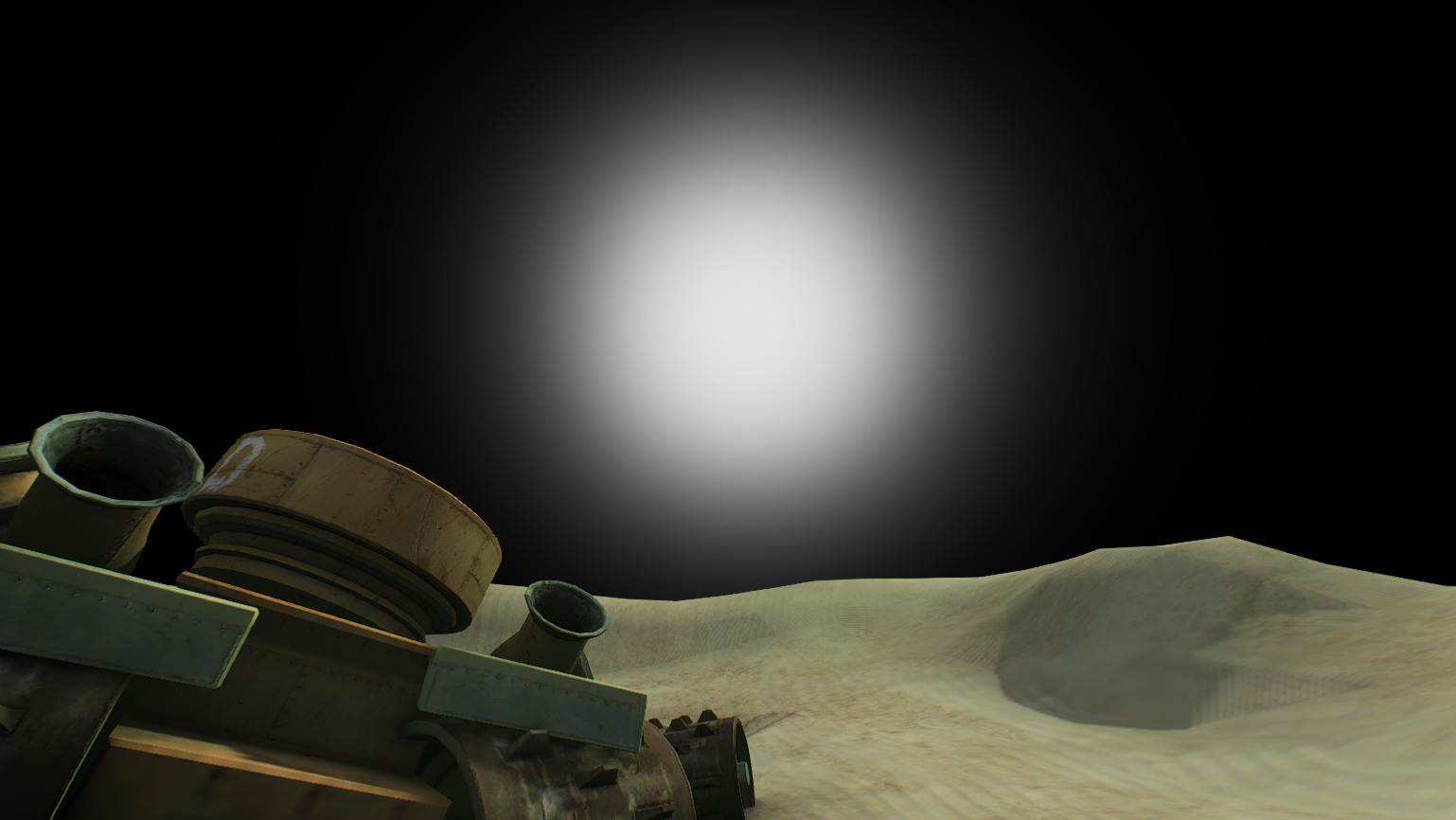
The sun
In The Witcher 3 (2015), the calculation of atmospheric scattering and the Sun consists of two separate drawing calls:

Witcher 3 (2015) - Until

Witcher 3 (2015) - with the sky

Witcher 3 (2015) - with sky + Sun The
rendering of the Sun in the 2015 version is very similar to the rendering of the Moon in terms of geometry and mixing / depth states.
On the other hand, in "Blood and Wine" the sky with the Sun is rendered in one pass:

The Witcher 3: Blood and Wine (2016) - To Heaven
The Witcher 3: Blood and Wine (2016) - with the sky and the Sun
No matter how you render the Sun, at some point you still need the (normalized) direction of sunlight. The most logical way to get this vector is to use spherical coordinates . In fact, we need only two values that indicate two angles (in radians!): Phi and theta . Having received them, we can assume that r = 1 , thus reducing it. Then for the Cartesian coordinates with the Y axis pointing up, you can write the following code in HLSL:
 float3 vSunDir;
 vSunDir.x = sin(fTheta)*cos(fPhi);
 vSunDir.y = sin(fTheta)*sin(fPhi);
 vSunDir.z = cos(fTheta);
 vSunDir = normalize(vSunDir);
Typically, the direction of sunlight is calculated in the application, and then passed to the constant buffer for future use.
Having received the direction of sunlight, we can delve deeper into the assembler code of the “Blood and Wine” pixel shader ...
  ...
  100: add r1.xyw, -r0.xyxz, cb12[0].xyxz
  101: dp3 r2.x, r1.xywx, r1.xywx
  102: rsq r2.x, r2.x
  103: mul r1.xyw, r1.xyxw, r2.xxxx
  104: mov_sat r2.xy, cb12[205].yxyy
  105: dp3 r2.z, -r1.xywx, -r1.xywx
  106: rsq r2.z, r2.z
  107: mul r1.xyw, -r1.xyxw, r2.zzzz
  ...
So, firstly, cb12 [0] .xyz is the camera position, and in r0.xyz we store the vertex position (this is the output from the vertex shader). Therefore, line 100 computes the vector worldToCamera . But take a look at lines 105-107. We can write them as normalize (-worldToCamera) , i.e. we calculate the normalized cameraToWorld vector .
120: dp3_sat r1.x, cb12[203].yzwy, r1.xywxThen we compute the scalar product of the cameraToWorld and sunDirection vectors ! Remember that they must be normalized. We also saturate this full expression to limit it to the interval [0-1].
Excellent! This scalar product is stored in r1.x. Let's see where it applies next ...
  152: log r1.x, r1.x
  153: mul r1.x, r1.x, cb12[203].x
  154: exp r1.x, r1.x
  155: mul r1.x, r2.y, r1.x
The trinity “log, mul, exp” is exponentiation. As you can see, we raise our cosine (the scalar product of normalized vectors) to some extent. You may ask why. In this way, we can create a gradient that mimics the sun. (And line 155 affects the opacity of this gradient, so that we, for example, reset it to completely hide the Sun). Here are some examples:
exponent = 54

exponent = 2400
Having this gradient, we use it to interpolate between skyColor and sunColor ! To avoid artifacts, you need to saturate the value in line 120.
It is worth noting that this trick can be used to simulate the crowns of the moon (at low exponent values). To do this, we need the moonDirection vector , which can easily be calculated using spherical coordinates.
Ready-made HLSL code may look like the following snippet:
 float3 vCamToWorld = normalize( PosW – CameraPos );
 float cosTheta = saturate( dot(vSunDir, vCamToWorld) );
 float sunGradient = pow( cosTheta, sunExponent );
 float3 color = lerp( skyColor, sunColor, sunGradient );
Motion of stars
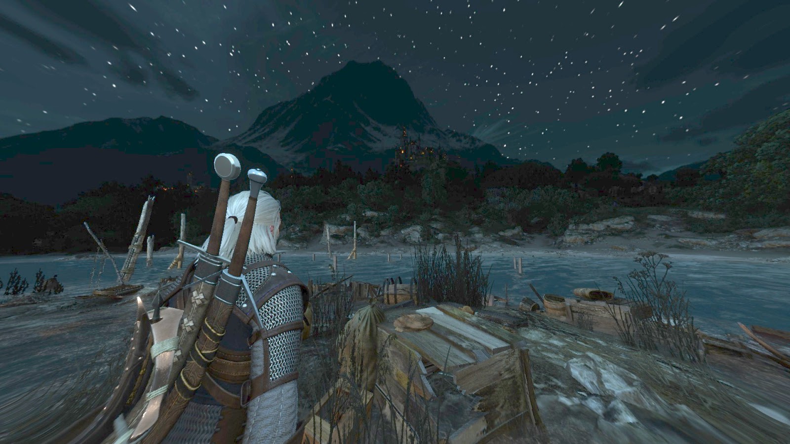
If you make a time-lapse of the clear night sky of Witcher 3, you can see that the stars are not static - they move a little across the sky! I noticed this almost by accident and wanted to know how it was implemented.
Let's start with the fact that the stars in Witcher 3 are presented as a cubic map of size 1024x1024x6. If you think about it, you can understand that this is a very convenient solution that allows you to easily snap directions for sampling a cubic map.
Let's look at the following assembler code:
  159: add r1.xyz, -v1.xyzx, cb1[8].xyzx
  160: dp3 r0.w, r1.xyzx, r1.xyzx
  161: rsq r0.w, r0.w
  162: mul r1.xyz, r0.wwww, r1.xyzx
  163: mul r2.xyz, cb12[204].zwyz, l(0.000000, 0.000000, 1.000000, 0.000000)
  164: mad r2.xyz, cb12[204].yzwy, l(0.000000, 1.000000, 0.000000, 0.000000), -r2.xyzx
  165: mul r4.xyz, r2.xyzx, cb12[204].zwyz
  166: mad r4.xyz, r2.zxyz, cb12[204].wyzw, -r4.xyzx
  167: dp3 r4.x, r1.xyzx, r4.xyzx
  168: dp2 r4.y, r1.xyxx, r2.yzyy
  169: dp3 r4.z, r1.xyzx, cb12[204].yzwy
  170: dp3 r0.w, r4.xyzx, r4.xyzx
  171: rsq r0.w, r0.w
  172: mul r2.xyz, r0.wwww, r4.xyzx
  173: sample_indexable(texturecube)(float,float,float,float) r4.xyz, r2.xyzx, t0.xyzw, s0
To calculate the final sampling vector (line 173), we start by calculating the normalized worldToCamera vector (lines 159-162).
Then we calculate two vector products (163-164, 165-166) with moonDirection , and later we calculate three scalar products to get the final sampling vector. HLSL Code:
 float3 vWorldToCamera = normalize( g_CameraPos.xyz - Input.PositionW.xyz );
 float3 vMoonDirection = cb12_v204.yzw;
 float3 vStarsSamplingDir = cross( vMoonDirection, float3(0, 0, 1) );
 float3 vStarsSamplingDir2 = cross( vStarsSamplingDir, vMoonDirection );
 float dirX = dot( vWorldToCamera, vStarsSamplingDir2 );
 float dirY = dot( vWorldToCamera, vStarsSamplingDir );
 float dirZ = dot( vWorldToCamera, vMoonDirection);
 float3 dirXYZ = normalize( float3(dirX, dirY, dirZ) );
 float3 starsColor = texNightStars.Sample( samplerAnisoWrap, dirXYZ ).rgb;
Note to myself: this is a very well-designed code, and I should investigate it in more detail.
Note to readers: if you know more about this operation, then tell me!
Twinkling stars
Another interesting trick that I would like to explore in more detail is the flickering of stars. For example, if you wander around Novigrad in clear weather, you will notice that the stars twinkle.
I was curious how this was implemented. It turned out that the difference between the 2015 version and “Blood and Wine” is quite large. For simplicity, I will consider the 2015 version.
So, we start right after sampling starsColor from the previous section:
  174: mul r0.w, v0.x, l(100.000000)
  175: round_ni r1.w, r0.w
  176: mad r2.w, v0.y, l(50.000000), cb0[0].x
  177: round_ni r4.w, r2.w
  178: bfrev r4.w, r4.w
  179: iadd r5.x, r1.w, r4.w
  180: ishr r5.y, r5.x, l(13)
  181: xor r5.x, r5.x, r5.y
  182: imul null, r5.y, r5.x, r5.x
  183: imad r5.y, r5.y, l(0x0000ec4d), l(0.0000000000000000000000000000000000001)
  184: imad r5.x, r5.x, r5.y, l(146956042240.000000)
  185: and r5.x, r5.x, l(0x7fffffff)
  186: itof r5.x, r5.x
  187: mad r5.y, v0.x, l(100.000000), l(-1.000000)
  188: round_ni r5.y, r5.y
  189: iadd r4.w, r4.w, r5.y
  190: ishr r5.z, r4.w, l(13)
  191: xor r4.w, r4.w, r5.z
  192: imul null, r5.z, r4.w, r4.w
  193: imad r5.z, r5.z, l(0x0000ec4d), l(0.0000000000000000000000000000000000001)
  194: imad r4.w, r4.w, r5.z, l(146956042240.000000)
  195: and r4.w, r4.w, l(0x7fffffff)
  196: itof r4.w, r4.w
  197: add r5.z, r2.w, l(-1.000000)
  198: round_ni r5.z, r5.z
  199: bfrev r5.z, r5.z
  200: iadd r1.w, r1.w, r5.z
  201: ishr r5.w, r1.w, l(13)
  202: xor r1.w, r1.w, r5.w
  203: imul null, r5.w, r1.w, r1.w
  204: imad r5.w, r5.w, l(0x0000ec4d), l(0.0000000000000000000000000000000000001)
  205: imad r1.w, r1.w, r5.w, l(146956042240.000000)
  206: and r1.w, r1.w, l(0x7fffffff)
  207: itof r1.w, r1.w
  208: mul r1.w, r1.w, l(0.000000001)
  209: iadd r5.y, r5.z, r5.y
  210: ishr r5.z, r5.y, l(13)
  211: xor r5.y, r5.y, r5.z
  212: imul null, r5.z, r5.y, r5.y
  213: imad r5.z, r5.z, l(0x0000ec4d), l(0.0000000000000000000000000000000000001)
  214: imad r5.y, r5.y, r5.z, l(146956042240.000000)
  215: and r5.y, r5.y, l(0x7fffffff)
  216: itof r5.y, r5.y
  217: frc r0.w, r0.w
  218: add r0.w, -r0.w, l(1.000000)
  219: mul r5.z, r0.w, r0.w
  220: mul r0.w, r0.w, r5.z
  221: mul r5.xz, r5.xxzx, l(0.000000001, 0.000000, 3.000000, 0.000000)
  222: mad r0.w, r0.w, l(-2.000000), r5.z
  223: frc r2.w, r2.w
  224: add r2.w, -r2.w, l(1.000000)
  225: mul r5.z, r2.w, r2.w
  226: mul r2.w, r2.w, r5.z
  227: mul r5.z, r5.z, l(3.000000)
  228: mad r2.w, r2.w, l(-2.000000), r5.z
  229: mad r4.w, r4.w, l(0.000000001), -r5.x
  230: mad r4.w, r0.w, r4.w, r5.x
  231: mad r5.x, r5.y, l(0.000000001), -r1.w
  232: mad r0.w, r0.w, r5.x, r1.w
  233: add r0.w, -r4.w, r0.w
  234: mad r0.w, r2.w, r0.w, r4.w
  235: mad r2.xyz, r0.wwww, l(0.000500, 0.000500, 0.000500, 0.000000), r2.xyzx
  236: sample_indexable(texturecube)(float,float,float,float) r2.xyz, r2.xyzx, t0.xyzw, s0
  237: log r4.xyz, r4.xyzx
  238: mul r4.xyz, r4.xyzx, l(2.200000, 2.200000, 2.200000, 0.000000)
  239: exp r4.xyz, r4.xyzx
  240: log r2.xyz, r2.xyzx
  241: mul r2.xyz, r2.xyzx, l(2.200000, 2.200000, 2.200000, 0.000000)
  242: exp r2.xyz, r2.xyzx
  243: mul r2.xyz, r2.xyzx, r4.xyzx
Hm. Let's take a look at the end of this fairly long assembly code.
After sampling starsColor on line 173, we calculate some sort of offset value . This offset is used to distort the first direction of sampling (r2.xyz, line 235), and then again we sample the cubic map of stars, perform gamma correction of these two values (237-242) and multiply them (243).
Simple, right? Well, not quite. Let's think about this offset a bit . This value should be different throughout the skydome - equally flickering stars would look very unrealistic.
To offsetwas as diverse as possible, we will take advantage of the fact that UVs are stretched to skydome (v0.xy) and apply the elapsed time stored in the constant buffer (cb [0] .x).
If you are unfamiliar with these frightening ishr / xor / and, then in the part about the lightning effect, read about integer noise.
As you can see, integer noise is caused four times here, but it differs from that used for lightning. To make the results even more random, the input integer for noise is the sum ( iadd ) and bits are inverted with it (internal function reversebits ; bfrev instruction ).
So, now slow down. Let's start from the beginning.
We have 4 “iterations” of integer noise. I analyzed the assembler code, the calculations of all 4 iterations look like this:
 int getInt( float x )
 {
     return asint( floor(x) );
 }
 int getReverseInt( float x )
 {
     return reversebits( getInt(x) );
 }
 // * Inputs - UV and elapsed time in seconds
 float2 starsUV;
 starsUV.x = 100.0 * Input.TextureUV.x;
 starsUV.y = 50.0  * Input.TextureUV.y + g_fTime;
 // * Iteration 1
 int iStars1_A = getReverseInt( starsUV.y );
 int iStars1_B = getInt( starsUV.x );
 float fStarsNoise1 = integerNoise( iStars1_A + iStars1_B );
 // * Iteration 2
 int iStars2_A = getReverseInt( starsUV.y );
 int iStars2_B = getInt( starsUV.x - 1.0 );
 float fStarsNoise2 = integerNoise( iStars2_A + iStars2_B );
 // * Iteration 3
 int iStars3_A = getReverseInt( starsUV.y - 1.0 );
 int iStars3_B = getInt( starsUV.x );
 float fStarsNoise3 = integerNoise( iStars3_A + iStars3_B );
 // * Iteration 4
 int iStars4_A = getReverseInt( starsUV.y - 1.0 );
 int iStars4_B = getInt( starsUV.x - 1.0 );
 float fStarsNoise4 = integerNoise( iStars4_A + iStars4_B );
The final output of all 4 iterations (follow the itof instructions to find them ):
Iteration 1 - r5.x,
Iteration 2 - r4.w,
Iteration 3 - r1.w,
Iteration 4 - r5.y
After the last itof (line 216) ) we have:
  217: frc r0.w, r0.w
  218: add r0.w, -r0.w, l(1.000000)
  219: mul r5.z, r0.w, r0.w
  220: mul r0.w, r0.w, r5.z
  221: mul r5.xz, r5.xxzx, l(0.000000001, 0.000000, 3.000000, 0.000000)
  222: mad r0.w, r0.w, l(-2.000000), r5.z
  223: frc r2.w, r2.w
  224: add r2.w, -r2.w, l(1.000000)
  225: mul r5.z, r2.w, r2.w
  226: mul r2.w, r2.w, r5.z
  227: mul r5.z, r5.z, l(3.000000)
  228: mad r2.w, r2.w, l(-2.000000), r5.z
These lines calculate the S-curve values for the balance based on the fractional part of UV, as in the case of lightning. So:
  float s_curve( float x )
  {
    float x2 = x * x;
    float x3 = x2 * x;
    // -2x^3 + 3x^2
    return -2.0*x3 + 3.0*x2;
  }
 ...
 // lines 217-222
 float weightX = 1.0 - frac( starsUV.x );
 weightX = s_curve( weightX );
 // lines 223-228
 float weightY = 1.0 - frac( starsUV.y );
 weightY = s_curve( weightY );
As you might expect, these coefficients are used to smoothly interpolate the noise and generate the final offset for the sampling coordinates:
  229: mad r4.w, r4.w, l(0.000000001), -r5.x
  230: mad r4.w, r0.w, r4.w, r5.x
  float noise0 = lerp( fStarsNoise1, fStarsNoise2, weightX );
  231: mad r5.x, r5.y, l(0.000000001), -r1.w
  232: mad r0.w, r0.w, r5.x, r1.w
  float noise1 = lerp( fStarsNoise3, fStarsNoise4, weightX );
  233: add r0.w, -r4.w, r0.w
  234: mad r0.w, r2.w, r0.w, r4.w
  float offset = lerp( noise0, noise1, weightY );
  235: mad r2.xyz, r0.wwww, l(0.000500, 0.000500, 0.000500, 0.000000), r2.xyzx
  236: sample_indexable(texturecube)(float,float,float,float) r2.xyz, r2.xyzx, t0.xyzw, s0
  float3 starsPerturbedDir = dirXYZ + offset * 0.0005;
  float3 starsColorDisturbed = texNightStars.Sample( samplerAnisoWrap, starsPerturbedDir ).rgb;
Here is a small visualization of the calculated offset :
After calculating starsColorDisturbed, the hardest part is complete. Hurrah!
The next step is to perform gamma correction for both starsColor and starsColorDisturbed , after which they are multiplied:
  starsColor = pow( starsColor, 2.2 );
  starsColorDisturbed = pow( starsColorDisturbed, 2.2 );
  float3 starsFinal = starsColor * starsColorDisturbed;
Stars - the finishing touches
We have starsFinal in r1.xyz. At the end of star processing, the following occurs:
  256: log r1.xyz, r1.xyzx
  257: mul r1.xyz, r1.xyzx, l(2.500000, 2.500000, 2.500000, 0.000000)
  258: exp r1.xyz, r1.xyzx
  259: min r1.xyz, r1.xyzx, l(1.000000, 1.000000, 1.000000, 0.000000)
  260: add r0.w, -cb0[9].w, l(1.000000)
  261: mul r1.xyz, r0.wwww, r1.xyzx
  262: mul r1.xyz, r1.xyzx, l(10.000000, 10.000000, 10.000000, 0.000000)
This is much easier compared to twinkling and moving stars.
So, we start by raising starsFinal to a power of 2.5 - this allows us to control the density of stars. Pretty clever. Then we make the maximum color of the stars equal float3 (1, 1, 1).
cb0 [9] .w is used to control the overall visibility of stars. Therefore, we can expect that in the daytime this value is 1.0 (which gives a multiplication by zero), and at night - 0.0.
In the end, we increase the visibility of stars by 10. And that’s it!
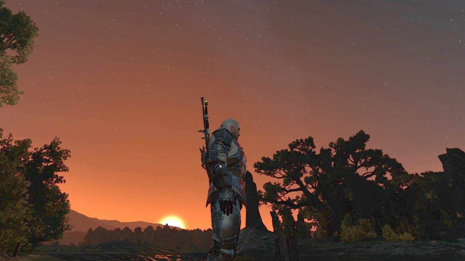
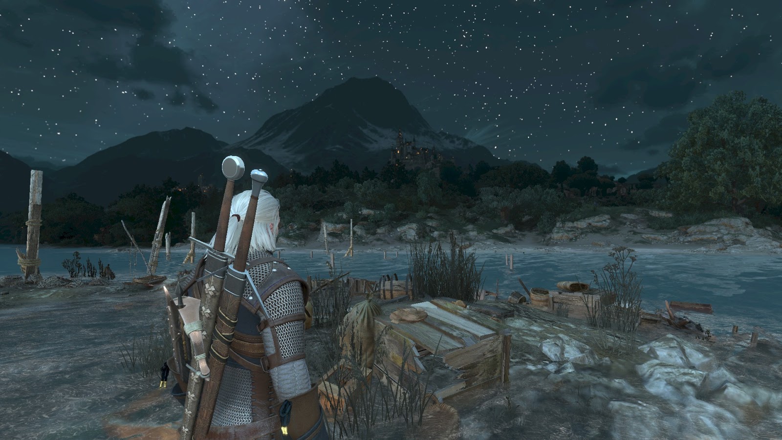
Part 3. The Witcher Flair (objects and brightness map)
Almost all of the previously described effects and techniques were not really associated with Witcher 3. Things like tone correction, vignetting, or calculating average brightness are present in almost every modern game. Even the effect of intoxication is quite widespread.
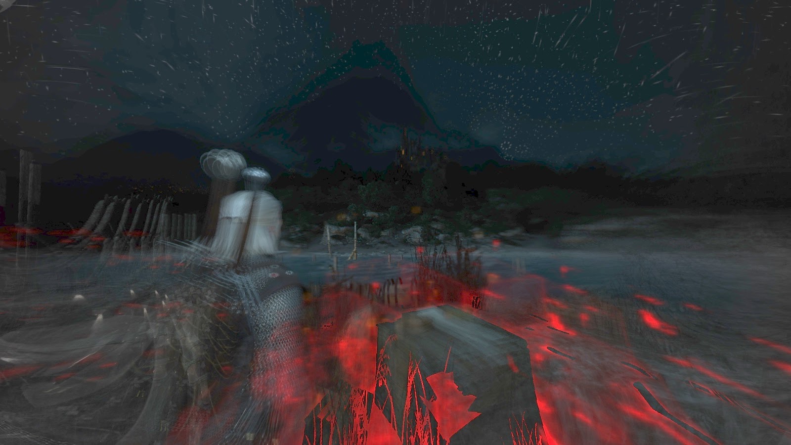
That is why I decided to take a closer look at the rendering mechanics of the “witcher instinct”. Geralt is a witcher, and therefore his feelings are much sharper than that of an ordinary person. Consequently, he can see and hear more than other people, which greatly helps him in his investigations. The witcher's flair mechanics allow the player to visualize such traces.
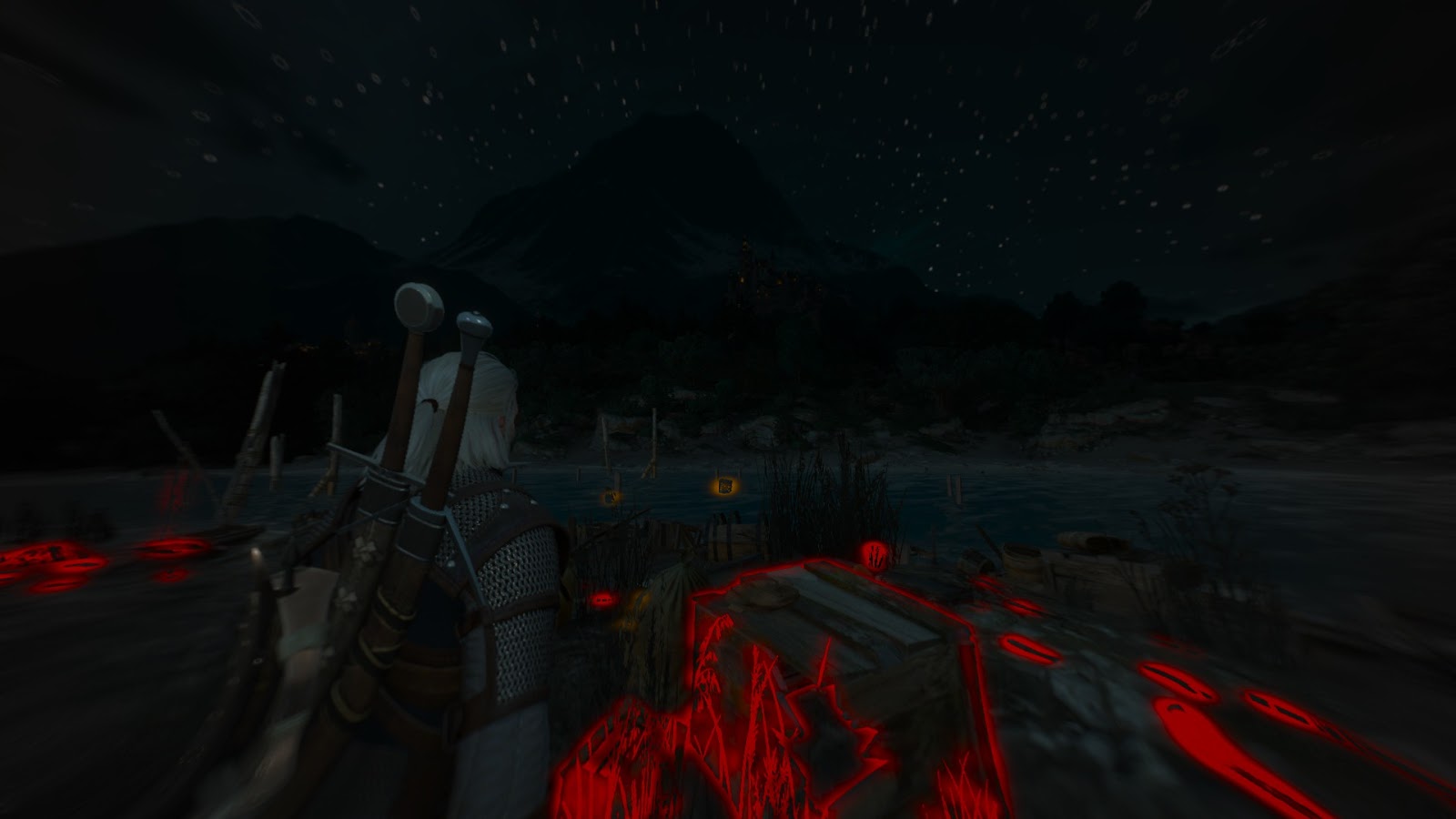
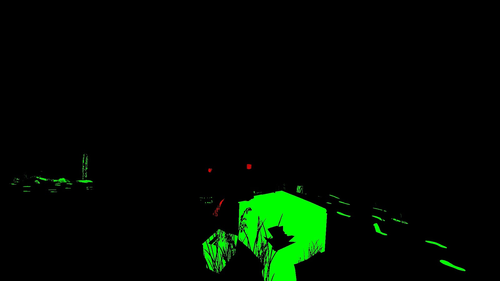
Here is a demonstration of the effect:
And one more, with better lighting:
As you can see, there are two types of objects: those with which Geralt can interact (yellow outline) and traces associated with the investigation (red outline). After Geralt examines the red trail, it can turn into yellow (first video). Notice that the entire screen turns gray and a fish-eye effect (second video) is added.
This effect is rather complicated, so I decided to divide his research into three parts.
In the first I will talk about the selection of objects, in the second - about the generation of the contour, and in the third - about the final unification of all this into one whole.
Select Objects
As I said, there are two types of objects, and we need to distinguish between them. In Witcher 3, this is implemented using a stencil buffer. When generating GBuffer meshes that should be marked as “traces” (red), they are rendered with stencil = 8. Meshes marked with yellow as “interesting” objects are rendered with stencil = 4.
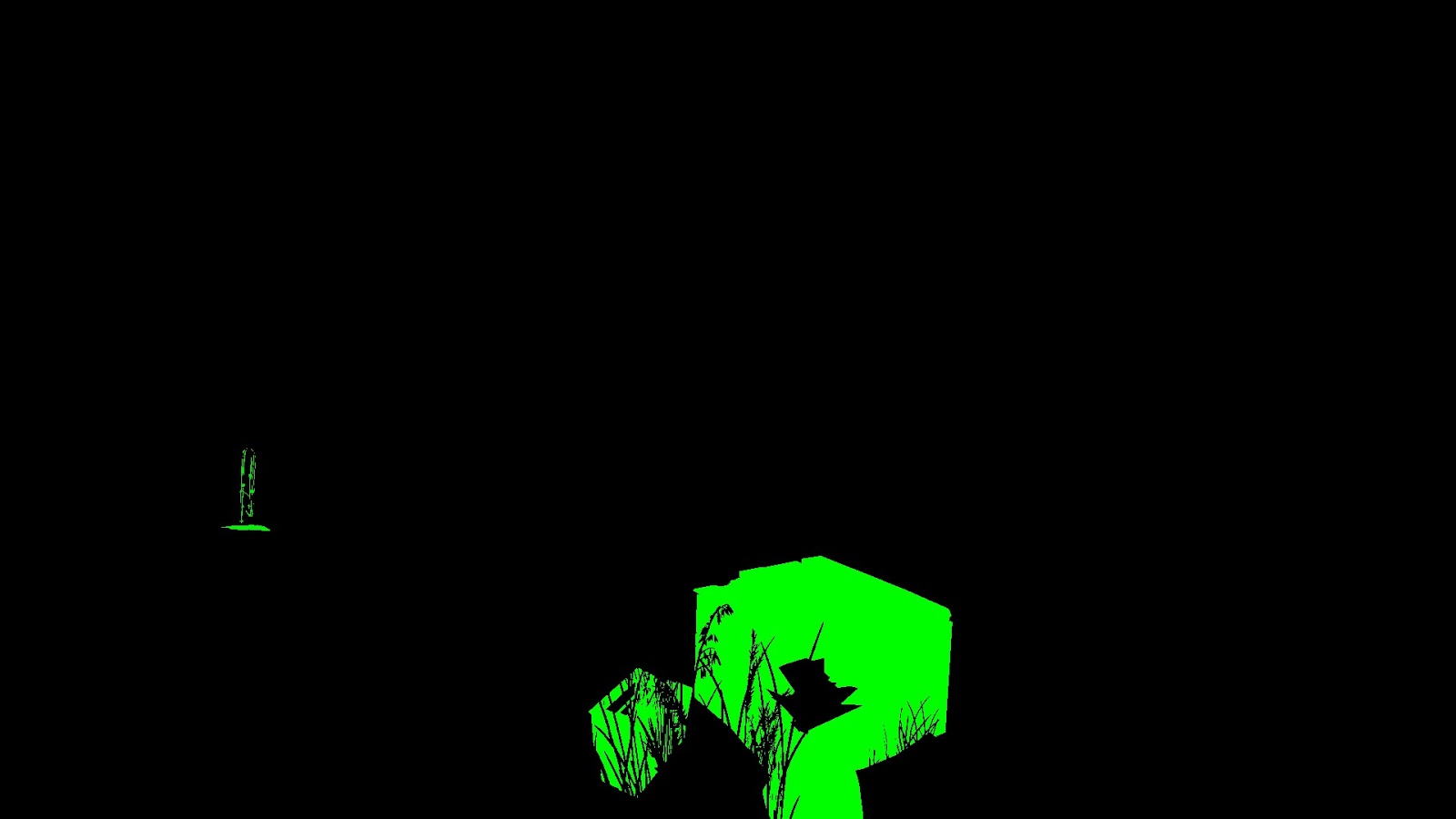
For example, the following two textures show an example frame with visible witcher instinct and the corresponding stencil buffer:

Stencil Buffer Brief
Stencil buffer is often used in games to tag meshes. Certain categories of meshes are assigned the same ID.
The idea is to use the Always function with the Replace operator if the stencil test is successful, and with the Keep operator in all other cases.
Here's how it is implemented using D3D11:
 D3D11_DEPTH_STENCIL_DESC depthstencilState;
 // Set depth parameters....
 // Enable stencil
 depthstencilState.StencilEnable = TRUE;
 // Read & write all bits
 depthstencilState.StencilReadMask = 0xFF;
 depthstencilState.StencilWriteMask = 0xFF;
 // Stencil operator for front face
 depthstencilState.FrontFace.StencilFunc = D3D11_COMPARISON_ALWAYS;
 depthstencilState.FrontFace.StencilDepthFailOp = D3D11_STENCIL_OP_KEEP;
 depthstencilState.FrontFace.StencilFailOp = D3D11_STENCIL_OP_KEEP;
 depthstencilState.FrontFace.StencilPassOp = D3D11_STENCIL_OP_REPLACE;
 // Stencil operator for back face.
 depthstencilState.BackFace.StencilFunc = D3D11_COMPARISON_ALWAYS;
 depthstencilState.BackFace.StencilDepthFailOp = D3D11_STENCIL_OP_KEEP;
 depthstencilState.BackFace.StencilFailOp = D3D11_STENCIL_OP_KEEP;
 depthstencilState.BackFace.StencilPassOp = D3D11_STENCIL_OP_REPLACE;
 pDevice->CreateDepthStencilState( &depthstencilState, &m_pDS_AssignValue );
The stensil value to be written to the buffer is passed as a StencilRef in the API call:
// from now on set stencil buffer values to 8
pDevCon->OMSetDepthStencilState( m_pDS_AssignValue, 8 );
...
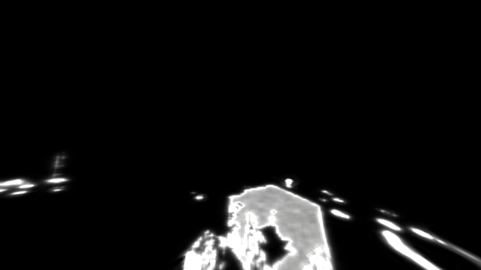
pDevCon->DrawIndexed( ... );Rendering brightness
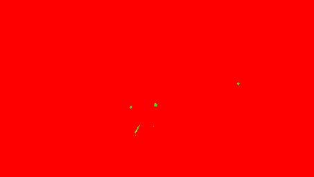
In this passage, from the point of view of implementation, there is one full-screen texture in the R11G11B10_FLOAT format, into which interesting objects and traces are stored in the channels R and G.
Why do we need this in terms of brightness? It turns out that Geralt's instinct has a limited radius, so objects only get outlines when the player is close enough to them.
Look at this aspect in action:
We start by cleaning the brightness texture, filling it with black.
Then two full-screen draw calls are made: the first for the trace, the second for interesting objects:
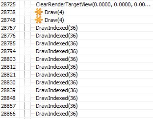
The first draw call is made for traces - the green channel:
The second call is made for interesting objects - the red channel:

Well, but how do we determine which pixels to consider? We'll have to use the stencil buffer!
For each of these calls, a stencil test is performed, and only those pixels that were previously marked as “8” (first draw call) or “4” are accepted.
Visualization of the stencil test for traces:

... and for interesting objects:
How is the test performed in this case? You can learn about the basics of stencil testing in a good post . In general, the stencil test formula has the following form:
 if (StencilRef & StencilReadMask OP StencilValue & StencilReadMask)
   accept pixel
 else
   discard pixel
where:
StencilRef is the value passed by the API call,
StencilReadMask is the mask used to read the stensil value (note that it is present on both the left and right sides),
OP is the comparison operator, set via the API,
StencilValue is the stencil buffer value in the current pixel being processed.
It is important to understand that we use binary ANDs to calculate the operands.
After getting acquainted with the basics, let's see how these parameters are used in these draw calls:
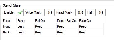
Stencil Condition for Traces

Stencil state for interesting objects
Ha! As we can see, the only difference is ReadMask. Let's check it out! Substitute these values in the stencil test equation:
 Let StencilReadMask = 0x08 and StencilRef = 0:
 For a pixel with stencil = 8:
 0 & 0x08 < 8 & 0x08
 0 < 8
 TRUE
 For a pixel with stencil = 4:
 0 & 0x08 < 4 & 0x08
 0 < 0
 FALSE
Cleverly. As you can see, in this case we do not compare the stensil value, but check whether a certain bit of the stencil buffer is set. Each pixel of the stencil buffer has the uint8 format, so the interval of values is [0-255].
Note: all DrawIndexed (36) calls are related to the rendering of footprints as footprints, so in this particular frame the brightness map has the following final form:
But before the stencil test there is a pixel shader. Both 28738 and 28748 use the same pixel shader:
 ps_5_0
    dcl_globalFlags refactoringAllowed
    dcl_constantbuffer cb0[2], immediateIndexed
    dcl_constantbuffer cb3[8], immediateIndexed
    dcl_constantbuffer cb12[214], immediateIndexed
    dcl_sampler s15, mode_default
    dcl_resource_texture2d (float,float,float,float) t15
    dcl_input_ps_siv v0.xy, position
    dcl_output o0.xyzw
    dcl_output o1.xyzw
    dcl_output o2.xyzw
    dcl_output o3.xyzw
    dcl_temps 2
   0: mul r0.xy, v0.xyxx, cb0[1].zwzz
   1: sample_indexable(texture2d)(float,float,float,float) r0.x, r0.xyxx, t15.xyzw, s15
   2: mul r1.xyzw, v0.yyyy, cb12[211].xyzw
   3: mad r1.xyzw, cb12[210].xyzw, v0.xxxx, r1.xyzw
   4: mad r0.xyzw, cb12[212].xyzw, r0.xxxx, r1.xyzw
   5: add r0.xyzw, r0.xyzw, cb12[213].xyzw
   6: div r0.xyz, r0.xyzx, r0.wwww
   7: add r0.xyz, r0.xyzx, -cb3[7].xyzx
   8: dp3 r0.x, r0.xyzx, r0.xyzx
   9: sqrt r0.x, r0.x
  10: mul r0.y, r0.x, l(0.120000)
  11: log r1.x, abs(cb3[6].y)
  12: mul r1.xy, r1.xxxx, l(2.800000, 0.800000, 0.000000, 0.000000)
  13: exp r1.xy, r1.xyxx
  14: mad r0.zw, r1.xxxy, l(0.000000, 0.000000, 120.000000, 120.000000), l(0.000000, 0.000000, 1.000000, 1.000000)
  15: lt r1.x, l(0.030000), cb3[6].y
  16: movc r0.xy, r1.xxxx, r0.yzyy, r0.xwxx
  17: div r0.x, r0.x, r0.y
  18: log r0.x, r0.x
  19: mul r0.x, r0.x, l(1.600000)
  20: exp r0.x, r0.x
  21: add r0.x, -r0.x, l(1.000000)
  22: max r0.x, r0.x, l(0)
  23: mul o0.xyz, r0.xxxx, cb3[0].xyzx
  24: mov o0.w, cb3[0].w
  25: mov o1.xyzw, cb3[1].xyzw
  26: mov o2.xyzw, cb3[2].xyzw
  27: mov o3.xyzw, cb3[3].xyzw
  28: ret
This pixel shader writes to only one render target, so lines 24-27 are redundant.
The first thing that happens here is depth sampling (with a point sampler with a value limit), line 1. This value is used to recreate a position in the world by multiplying by a special matrix, followed by perspective division (lines 2-6).
Taking the position of Geralt (cb3 [7] .xyz - note that this is not the position of the camera!), We calculate the distance from Geralt to this particular point (lines 7-9).
The following input is important in this shader:
- cb3 [0] .rgb - output color. It can have the format float3 (0, 1, 0) (traces) or float3 (1, 0, 0) (interesting objects),
- cb3 [6] .y - distance scaling factor. Directly affects the radius and brightness of the final output.
Later, we have pretty tricky formulas for calculating brightness depending on the distance between Geralt and the object. I can assume that all the coefficients are selected experimentally.
The final output is color * intensity .
The HLSL code will look something like this:
 struct FSInput
 {
      float4 param0 : SV_Position;
 };
 struct FSOutput
 {
      float4 param0 : SV_Target0;
      float4 param1 : SV_Target1;
      float4 param2 : SV_Target2;
      float4 param3 : SV_Target3;
 };
 float3 getWorldPos( float2 screenPos, float depth )
 {
   float4 worldPos = float4(screenPos, depth, 1.0);
   worldPos = mul( worldPos, screenToWorld );
   return worldPos.xyz / worldPos.w;
 }
 FSOutput EditedShaderPS(in FSInput IN)
 {
   // * Inputs
   // Directly affects radius of the effect
   float distanceScaling = cb3_v6.y;
   // Color of output at the end
   float3 color = cb3_v0.rgb;
   // Sample depth
   float2 uv = IN.param0.xy * cb0_v1.zw;
   float depth = texture15.Sample( sampler15, uv ).x;
   // Reconstruct world position
   float3 worldPos = getWorldPos( IN.param0.xy, depth );
   // Calculate distance from Geralt to world position of particular object
   float dist_geraltToWorld = length( worldPos - cb3_v7.xyz );
   // Calculate two squeezing params
   float t0 = 1.0 + 120*pow( abs(distanceScaling), 2.8 );
   float t1 = 1.0 + 120*pow( abs(distanceScaling), 0.8 );
   // Determine nominator and denominator
   float2 params;
   params = (distanceScaling > 0.03) ? float2(dist_geraltToWorld * 0.12, t0) : float2(dist_geraltToWorld, t1);
   // Distance Geralt <-> Object
   float nominator = params.x;
   // Hiding factor
   float denominator = params.y;
   // Raise to power of 1.6
   float param = pow( params.x / params.y, 1.6 );
   // Calculate final intensity
   float intensity = max(0.0, 1.0 - param );
   // * Final outputs.
   // *
   // * This PS outputs only one color, the rest
   // * is redundant. I just added this to keep 1-1 ratio with
   // * original assembly.
   FSOutput OUT = (FSOutput)0;
   OUT.param0.xyz = color * intensity;
   // == redundant ==
   OUT.param0.w = cb3_v0.w;
   OUT.param1 = cb3_v1;
   OUT.param2 = cb3_v2;
   OUT.param3 = cb3_v3;
   // ===============
   return OUT;
 }
A small comparison of the original (left) and my (right) assembler shader code.

This was the first stage of the witch's flair effect . In fact, it is the simplest.
Part 4. The Witcher Flair (outline map)
Once again, take a look at the scene we are exploring:
In the first part of the analysis of the effect of the witch’s instinct, I showed how the “brightness map” is generated.
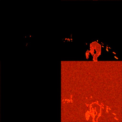
We have one full-screen texture of the R11G11B10_FLOAT format, which might look like this:
The green channel means “footprints”, the red - interesting objects with which Geralt can interact.
Having received this texture, we can proceed to the next stage - I called it the “contour map”.
This is a bit weird texture of the 512x512 R16G16_FLOAT format. It is important that it is implemented in the style of “ping pong”. The contour map from the previous frame is the input data (along with the brightness map) to generate a new contour map in the current frame.
Ping-pong buffers can be implemented in many ways, but I personally like the following (pseudocode) most of all:
 // Declarations
 Texture2D m_texOutlineMap[2];
 uint m_outlineIndex = 0;
 // Rendering
 void Render()
 {
   pDevCon->SetInputTexture( m_texOutlineMap[m_outlineIndex] );
   pDevCon->SetOutputTexture( m_texOutlineMap[!m_outlineIndex] );
   ...
   pDevCon->Draw(...);
   // after draw
   m_outlineIndex = !m_outlineIndex;
 }
This approach, where the input is always [m_outlineIndex] , and the output is always [! M_outlineIndex] , provides flexibility for the use of further post-effects.
Let's take a look at the pixel shader:
 ps_5_0
    dcl_globalFlags refactoringAllowed
    dcl_constantbuffer cb3[1], immediateIndexed
    dcl_sampler s0, mode_default
    dcl_sampler s1, mode_default
    dcl_resource_texture2d (float,float,float,float) t0
    dcl_resource_texture2d (float,float,float,float) t1
    dcl_input_ps linear v2.xy
    dcl_output o0.xyzw
    dcl_temps 4
   0: add r0.xyzw, v2.xyxy, v2.xyxy
   1: round_ni r1.xy, r0.zwzz
   2: frc r0.xyzw, r0.xyzw
   3: add r1.zw, r1.xxxy, l(0.000000, 0.000000, -1.000000, -1.000000)
   4: dp2 r1.z, r1.zwzz, r1.zwzz
   5: add r1.z, -r1.z, l(1.000000)
   6: max r2.w, r1.z, l(0)
   7: dp2 r1.z, r1.xyxx, r1.xyxx
   8: add r3.xyzw, r1.xyxy, l(-1.000000, -0.000000, -0.000000, -1.000000)
   9: add r1.x, -r1.z, l(1.000000)
  10: max r2.x, r1.x, l(0)
  11: dp2 r1.x, r3.xyxx, r3.xyxx
  12: dp2 r1.y, r3.zwzz, r3.zwzz
  13: add r1.xy, -r1.xyxx, l(1.000000, 1.000000, 0.000000, 0.000000)
  14: max r2.yz, r1.xxyx, l(0, 0, 0, 0)
  15: sample_indexable(texture2d)(float,float,float,float) r1.xyzw, r0.zwzz, t1.xyzw, s1
  16: dp4 r1.x, r1.xyzw, r2.xyzw
  17: add r2.xyzw, r0.zwzw, l(0.003906, 0.000000, -0.003906, 0.000000)
  18: add r0.xyzw, r0.xyzw, l(0.000000, 0.003906, 0.000000, -0.003906)
  19: sample_indexable(texture2d)(float,float,float,float) r1.yz, r2.xyxx, t1.zxyw, s1
  20: sample_indexable(texture2d)(float,float,float,float) r2.xy, r2.zwzz, t1.xyzw, s1
  21: add r1.yz, r1.yyzy, -r2.xxyx
  22: sample_indexable(texture2d)(float,float,float,float) r0.xy, r0.xyxx, t1.xyzw, s1
  23: sample_indexable(texture2d)(float,float,float,float) r0.zw, r0.zwzz, t1.zwxy, s1
  24: add r0.xy, -r0.zwzz, r0.xyxx
  25: max r0.xy, abs(r0.xyxx), abs(r1.yzyy)
  26: min r0.xy, r0.xyxx, l(1.000000, 1.000000, 0.000000, 0.000000)
  27: mul r0.xy, r0.xyxx, r1.xxxx
  28: sample_indexable(texture2d)(float,float,float,float) r0.zw, v2.xyxx, t0.zwxy, s0
  29: mad r0.w, r1.x, l(0.150000), r0.w
  30: mad r0.x, r0.x, l(0.350000), r0.w
  31: mad r0.x, r0.y, l(0.350000), r0.x
  32: mul r0.yw, cb3[0].zzzw, l(0.000000, 300.000000, 0.000000, 300.000000)
  33: mad r0.yw, v2.xxxy, l(0.000000, 150.000000, 0.000000, 150.000000), r0.yyyw
  34: ftoi r0.yw, r0.yyyw
  35: bfrev r0.w, r0.w
  36: iadd r0.y, r0.w, r0.y
  37: ishr r0.w, r0.y, l(13)
  38: xor r0.y, r0.y, r0.w
  39: imul null, r0.w, r0.y, r0.y
  40: imad r0.w, r0.w, l(0x0000ec4d), l(0.0000000000000000000000000000000000001)
  41: imad r0.y, r0.y, r0.w, l(146956042240.000000)
  42: and r0.y, r0.y, l(0x7fffffff)
  43: itof r0.y, r0.y
  44: mad r0.y, r0.y, l(0.000000001), l(0.650000)
  45: add_sat r1.xyzw, v2.xyxy, l(0.001953, 0.000000, -0.001953, 0.000000)
  46: sample_indexable(texture2d)(float,float,float,float) r0.w, r1.xyxx, t0.yzwx, s0
  47: sample_indexable(texture2d)(float,float,float,float) r1.x, r1.zwzz, t0.xyzw, s0
  48: add r0.w, r0.w, r1.x
  49: add_sat r1.xyzw, v2.xyxy, l(0.000000, 0.001953, 0.000000, -0.001953)
  50: sample_indexable(texture2d)(float,float,float,float) r1.x, r1.xyxx, t0.xyzw, s0
  51: sample_indexable(texture2d)(float,float,float,float) r1.y, r1.zwzz, t0.yxzw, s0
  52: add r0.w, r0.w, r1.x
  53: add r0.w, r1.y, r0.w
  54: mad r0.w, r0.w, l(0.250000), -r0.z
  55: mul r0.w, r0.y, r0.w
  56: mul r0.y, r0.y, r0.z
  57: mad r0.x, r0.w, l(0.900000), r0.x
  58: mad r0.y, r0.y, l(-0.240000), r0.x
  59: add r0.x, r0.y, r0.z
  60: mov_sat r0.z, cb3[0].x
  61: log r0.z, r0.z
  62: mul r0.z, r0.z, l(100.000000)
  63: exp r0.z, r0.z
  64: mad r0.z, r0.z, l(0.160000), l(0.700000)
  65: mul o0.xy, r0.zzzz, r0.xyxx
  66: mov o0.zw, l(0, 0, 0, 0)
  67: ret
As you can see, the output contour map is divided into four equal squares, and this is the first thing we need to study:
0: add r0.xyzw, v2.xyxy, v2.xyxy
1: round_ni r1.xy, r0.zwzz
2: frc r0.xyzw, r0.xyzw
3: add r1.zw, r1.xxxy, l(0.000000, 0.000000, -1.000000, -1.000000)
4: dp2 r1.z, r1.zwzz, r1.zwzz
5: add r1.z, -r1.z, l(1.000000)
6: max r2.w, r1.z, l(0)
7: dp2 r1.z, r1.xyxx, r1.xyxx
8: add r3.xyzw, r1.xyxy, l(-1.000000, -0.000000, -0.000000, -1.000000)
9: add r1.x, -r1.z, l(1.000000)
10: max r2.x, r1.x, l(0)
11: dp2 r1.x, r3.xyxx, r3.xyxx
12: dp2 r1.y, r3.zwzz, r3.zwzz
13: add r1.xy, -r1.xyxx, l(1.000000, 1.000000, 0.000000, 0.000000)
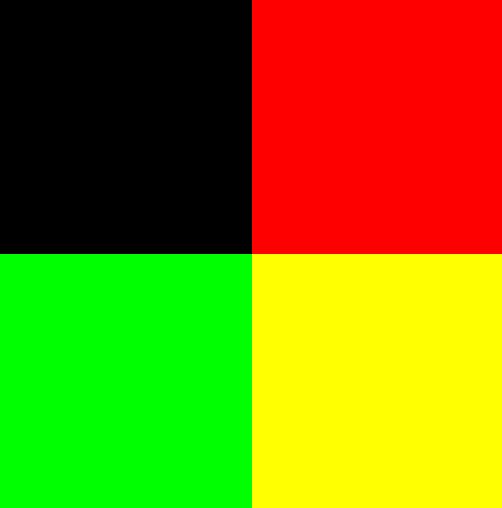
14: max r2.yz, r1.xxyx, l(0, 0, 0, 0)We start by calculating floor (TextureUV * 2.0), which gives us the following:
To determine the individual squares, a small function is used:
 float getParams(float2 uv)
 {
      float d = dot(uv, uv);
      d = 1.0 - d;
      d = max( d, 0.0 );
      return d;
 }
Notice that the function returns 1.0 with input float2 (0.0, 0.0).
This case occurs in the upper left corner. To get the same situation in the upper right corner, subtract float2 (1, 0) from the rounded texcoords, subtract float2 (0, 1) for the green square, and float2 (1.0, 1.0) for the yellow square.
So:
   float2 flooredTextureUV = floor( 2.0 * TextureUV );
   ...
   float2 uv1 = flooredTextureUV;
   float2 uv2 = flooredTextureUV + float2(-1.0, -0.0);
   float2 uv3 = flooredTextureUV + float2( -0.0, -1.0);
   float2 uv4 = flooredTextureUV + float2(-1.0, -1.0);
   float4 mask;
   mask.x = getParams( uv1 );
   mask.y = getParams( uv2 );
   mask.z = getParams( uv3 );
   mask.w = getParams( uv4 );
Each of the mask components is either zero or one, and is responsible for one square of the texture. For example, mask.r and mask.w :

mask.r

mask.w
We got mask , let's move on. Line 15 samples the luminance map. Note that the luminance texture is in the format R11G11B10_FLOAT, although we sample all the rgba components. In this situation, it is assumed that .a is 1.0f.
The Texcoords used for this operation can be computed as frac (TextureUV * 2.0) . Therefore, the result of this operation may, for example, look like this:

See the resemblance?
The next step is very smart - the four-component scalar product (dp4) is performed:
16: dp4 r1.x, r1.xyzw, r2.xyzwThus, only the red channel (that is, only interesting objects) remains in the upper left corner, only the green channel in the upper right (only traces), and everything in the lower right (because the luminance component .w is indirectly set to 1.0). Great idea. The result of the scalar product looks like this:

Having received this masterFilter , we are ready to determine the contours of objects. It is not as difficult as it may seem. The algorithm is very similar to that used to obtain sharpness - we need to get the maximum absolute difference of values.
Here's what happens: we sample four texels next to the current texel being processed (important: in this case, the texel size is 1.0 / 256.0!) And calculate the maximum absolute differences for the red and green channels:
   float fTexel = 1.0 / 256;
   float2 sampling1 = TextureUV + float2( fTexel, 0 );
   float2 sampling2 = TextureUV + float2( -fTexel, 0 );
   float2 sampling3 = TextureUV + float2( 0, fTexel );
   float2 sampling4 = TextureUV + float2( 0, -fTexel );
   float2 intensity_x0 = texIntensityMap.Sample( sampler1, sampling1 ).xy;
   float2 intensity_x1 = texIntensityMap.Sample( sampler1, sampling2 ).xy;
   float2 intensity_diff_x = intensity_x0 - intensity_x1;
   float2 intensity_y0 = texIntensityMap.Sample( sampler1, sampling3 ).xy;
   float2 intensity_y1 = texIntensityMap.Sample( sampler1, sampling4 ).xy;
   float2 intensity_diff_y = intensity_y0 - intensity_y1;
   float2 maxAbsDifference = max( abs(intensity_diff_x), abs(intensity_diff_y) );
   maxAbsDifference = saturate(maxAbsDifference);
Now if we multiply filter by maxAbsDifference ...
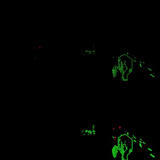
Very simple and efficient.
Having received the contours, we sample the contour map from the previous frame.
Then, in order to get a “ghostly” effect, we take a part of the parameters calculated on the current pass and the values from the contour map.
Say hello to our old friend - integer noise. He is present here. Animation parameters (cb3 [0] .zw) are taken from the constant buffer and change over time.
   float2 outlines = masterFilter * maxAbsDifference;
   // Sample outline map
   float2 outlineMap = texOutlineMap.Sample( samplerLinearWrap, uv ).xy;
   // I guess it's related with ghosting
   float paramOutline = masterFilter*0.15 + outlineMap.y;
   paramOutline += 0.35 * outlines.r;
   paramOutline += 0.35 * outlines.g;
   // input for integer noise
   float2 noiseWeights = cb3_v0.zw;
   float2 noiseInputs = 150.0*uv + 300.0*noiseWeights;
   int2 iNoiseInputs = (int2) noiseInputs;
   float noise0 = clamp( integerNoise( iNoiseInputs.x + reversebits(iNoiseInputs.y) ), -1, 1 ) + 0.65; // r0.y
Note: if you want to implement the witch's instinct yourself, I recommend limiting the integer noise to the interval [-1; 1] (as said on his website). There was no restriction in the original TW3 shader, but without it I got terrible artifacts and the entire outline map was unstable.
Then we sample the contour map in the same way as the brightness map earlier (this time the texel has a size of 1.0 / 512.0), and calculate the average value of the .x component:
  // sampling of outline map
   fTexel = 1.0 / 512.0;
   sampling1 = saturate( uv + float2( fTexel, 0 ) );
   sampling2 = saturate( uv + float2( -fTexel, 0 ) );
   sampling3 = saturate( uv + float2( 0, fTexel ) );
   sampling4 = saturate( uv + float2( 0, -fTexel ) );
   float outline_x0 = texOutlineMap.Sample( sampler0, sampling1 ).x;
   float outline_x1 = texOutlineMap.Sample( sampler0, sampling2 ).x;
   float outline_y0 = texOutlineMap.Sample( sampler0, sampling3 ).x;
   float outline_y1 = texOutlineMap.Sample( sampler0, sampling4 ).x;
   float averageOutline = (outline_x0+outline_x1+outline_y0+outline_y1) / 4.0;
Then, judging by the assembler code, the difference between the average and the value of this particular pixel is calculated, after which distortion by integer noise is performed:
   // perturb with noise
   float frameOutlineDifference = averageOutline - outlineMap.x;
   frameOutlineDifference *= noise0;
The next step is to distort the value from the “old” contour map using noise - this is the main line that gives the output texture a blocky feel.
Then there are other calculations, after which, at the very end, the “attenuation” is calculated.
   // the main place with gives blocky look of texture
   float newNoise = outlineMap.x * noise0;
   float newOutline = frameOutlineDifference * 0.9 + paramOutline;
   newOutline -= 0.24*newNoise;
   // 59: add r0.x, r0.y, r0.z
   float2 finalOutline = float2( outlineMap.x + newOutline, newOutline);
   // * calculate damping
   float dampingParam = saturate( cb3_v0.x );
   dampingParam = pow( dampingParam, 100 );
   float damping = 0.7 + 0.16*dampingParam;
   // * final multiplication
   float2 finalColor = finalOutline * damping;
   return float4(finalColor, 0, 0);
Here's a short video demonstrating an outline map in action:
If you are interested in the full pixel shader, then it is available here . Shader is compatible with RenderDoc.
It is interesting (and, to be honest, slightly annoying) that despite the identity of the assembler code with the original shader from Witcher 3, the final appearance of the contour map in RenderDoc is changing!
Note: in the last pass (see the next part) you will see that only the .r channel of the contour map is used. Why then do we need the .g channel? I think that this is some kind of ping-pong buffer in one texture - note that .r contains the .g channel + some new value.
Part 5: The Witcher Flair (Fisheye and the final result)
We will briefly list what we already have: in the first part, dedicated to the witcher's instinct, a full-screen brightness map is generated that tells how noticeable the effect should be depending on the distance. In the second part, I examined in more detail the outline map, which is responsible for the outlines and animation of the finished effect.
We have come to the last stage. All this needs to be combined! The last pass is a full-screen quad. Inputs: color buffer, contour map, and luminance map.
Before:
After:
Once again I will show the video with the applied effect:
As you can see, in addition to applying contours to objects that Geralt can see or hear, the fish-eye effect is applied to the entire screen, and the entire screen (especially the corners) becomes grayish to convey the feeling of a real monster hunter.
Full assembled pixel shader code:
 ps_5_0
    dcl_globalFlags refactoringAllowed
    dcl_constantbuffer cb0[3], immediateIndexed
    dcl_constantbuffer cb3[7], immediateIndexed
    dcl_sampler s0, mode_default
    dcl_sampler s2, mode_default
    dcl_resource_texture2d (float,float,float,float) t0
    dcl_resource_texture2d (float,float,float,float) t2
    dcl_resource_texture2d (float,float,float,float) t3
    dcl_input_ps_siv v0.xy, position
    dcl_output o0.xyzw
    dcl_temps 7
   0: div r0.xy, v0.xyxx, cb0[2].xyxx
   1: mad r0.zw, r0.xxxy, l(0.000000, 0.000000, 2.000000, 2.000000), l(0.000000, 0.000000, -1.000000, -1.000000)
   2: mov r1.yz, abs(r0.zzwz)
   3: div r0.z, cb0[2].x, cb0[2].y
   4: mul r1.x, r0.z, r1.y
   5: add r0.zw, r1.xxxz, -cb3[2].xxxy
   6: mul_sat r0.zw, r0.zzzw, l(0.000000, 0.000000, 0.555556, 0.555556)
   7: log r0.zw, r0.zzzw
   8: mul r0.zw, r0.zzzw, l(0.000000, 0.000000, 2.500000, 2.500000)
   9: exp r0.zw, r0.zzzw
  10: dp2 r0.z, r0.zwzz, r0.zwzz
  11: sqrt r0.z, r0.z
  12: min r0.z, r0.z, l(1.000000)
  13: add r0.z, -r0.z, l(1.000000)
  14: mov_sat r0.w, cb3[6].x
  15: add_sat r1.xy, -r0.xyxx, l(0.030000, 0.030000, 0.000000, 0.000000)
  16: add r1.x, r1.y, r1.x
  17: add_sat r0.xy, r0.xyxx, l(-0.970000, -0.970000, 0.000000, 0.000000)
  18: add r0.x, r0.x, r1.x
  19: add r0.x, r0.y, r0.x
  20: mul r0.x, r0.x, l(20.000000)
  21: min r0.x, r0.x, l(1.000000)
  22: add r1.xy, v0.xyxx, v0.xyxx
  23: div r1.xy, r1.xyxx, cb0[2].xyxx
  24: add r1.xy, r1.xyxx, l(-1.000000, -1.000000, 0.000000, 0.000000)
  25: dp2 r0.y, r1.xyxx, r1.xyxx
  26: mul r1.xy, r0.yyyy, r1.xyxx
  27: mul r0.y, r0.w, l(0.100000)
  28: mul r1.xy, r0.yyyy, r1.xyxx
  29: max r1.xy, r1.xyxx, l(-0.400000, -0.400000, 0.000000, 0.000000)
  30: min r1.xy, r1.xyxx, l(0.400000, 0.400000, 0.000000, 0.000000)
  31: mul r1.xy, r1.xyxx, cb3[1].xxxx
  32: mul r1.zw, r1.xxxy, cb0[2].zzzw
  33: mad r1.zw, v0.xxxy, cb0[1].zzzw, -r1.zzzw
  34: sample_indexable(texture2d)(float,float,float,float) r2.xyz, r1.zwzz, t0.xyzw, s0
  35: mul r3.xy, r1.zwzz, l(0.500000, 0.500000, 0.000000, 0.000000)
  36: sample_indexable(texture2d)(float,float,float,float) r0.y, r3.xyxx, t2.yxzw, s2
  37: mad r3.xy, r1.zwzz, l(0.500000, 0.500000, 0.000000, 0.000000), l(0.500000, 0.000000, 0.000000, 0.000000)
  38: sample_indexable(texture2d)(float,float,float,float) r2.w, r3.xyxx, t2.yzwx, s2
  39: mul r2.w, r2.w, l(0.125000)
  40: mul r3.x, cb0[0].x, l(0.100000)
  41: add r0.x, -r0.x, l(1.000000)
  42: mul r0.xy, r0.xyxx, l(0.030000, 0.125000, 0.000000, 0.000000)
  43: mov r3.yzw, l(0, 0, 0, 0)
  44: mov r4.x, r0.y
  45: mov r4.y, r2.w
  46: mov r4.z, l(0)
  47: loop
  48:  ige r4.w, r4.z, l(8)
  49:  breakc_nz r4.w
  50:  itof r4.w, r4.z
  51:  mad r4.w, r4.w, l(0.785375), -r3.x
  52:  sincos r5.x, r6.x, r4.w
  53:  mov r6.y, r5.x
  54:  mul r5.xy, r0.xxxx, r6.xyxx
  55:  mad r5.zw, r5.xxxy, l(0.000000, 0.000000, 0.125000, 0.125000), r1.zzzw
  56:  mul r6.xy, r5.zwzz, l(0.500000, 0.500000, 0.000000, 0.000000)
  57:  sample_indexable(texture2d)(float,float,float,float) r4.w, r6.xyxx, t2.yzwx, s2
  58:  mad r4.x, r4.w, l(0.125000), r4.x
  59:  mad r5.zw, r5.zzzw, l(0.000000, 0.000000, 0.500000, 0.500000), l(0.000000, 0.000000, 0.500000, 0.000000)
  60:  sample_indexable(texture2d)(float,float,float,float) r4.w, r5.zwzz, t2.yzwx, s2
  61:  mad r4.y, r4.w, l(0.125000), r4.y
  62:  mad r5.xy, r5.xyxx, r1.xyxx, r1.zwzz
  63:  sample_indexable(texture2d)(float,float,float,float) r5.xyz, r5.xyxx, t0.xyzw, s0
  64:  mad r3.yzw, r5.xxyz, l(0.000000, 0.125000, 0.125000, 0.125000), r3.yyzw
  65:  iadd r4.z, r4.z, l(1)
  66: endloop
  67: sample_indexable(texture2d)(float,float,float,float) r0.xy, r1.zwzz, t3.xyzw, s0
  68: mad_sat r0.xy, -r0.xyxx, l(0.800000, 0.750000, 0.000000, 0.000000), r4.xyxx
  69: dp3 r1.x, r3.yzwy, l(0.300000, 0.300000, 0.300000, 0.000000)
  70: add r1.yzw, -r1.xxxx, r3.yyzw
  71: mad r1.xyz, r0.zzzz, r1.yzwy, r1.xxxx
  72: mad r1.xyz, r1.xyzx, l(0.600000, 0.600000, 0.600000, 0.000000), -r2.xyzx
  73: mad r1.xyz, r0.wwww, r1.xyzx, r2.xyzx
  74: mul r0.yzw, r0.yyyy, cb3[4].xxyz
  75: mul r2.xyz, r0.xxxx, cb3[5].xyzx
  76: mad r0.xyz, r0.yzwy, l(1.200000, 1.200000, 1.200000, 0.000000), r2.xyzx
  77: mov_sat r2.xyz, r0.xyzx
  78: dp3_sat r0.x, r0.xyzx, l(1.000000, 1.000000, 1.000000, 0.000000)
  79: add r0.yzw, -r1.xxyz, r2.xxyz
  80: mad o0.xyz, r0.xxxx, r0.yzwy, r1.xyzx
  81: mov o0.w, l(1.000000)
  82: ret
82 lines - so we have a lot of work to do!
First, take a look at the input data:
   // *** Inputs
   // * Zoom amount, always 1
   float zoomAmount = cb3_v1.x;
   // Another value which affect fisheye effect
   // but always set to float2(1.0, 1.0).
   float2 amount = cb0_v2.zw;
   // Elapsed time in seconds
   float time = cb0_v0.x;
   // Colors of witcher senses
   float3 colorInteresting = cb3_v5.rgb;
   float3 colorTraces = cb3_v4.rgb;
   // Was always set to float2(0.0, 0.0).
   // Setting this to higher values
   // makes "grey corners" effect weaker.
   float2 offset = cb3_v2.xy;
   // Dimensions of fullscreen
   float2 texSize = cb0_v2.xy;
   float2 invTexSize = cb0_v1.zw;
   // Main value which causes fisheye effect [0-1]
   const float fisheyeAmount = saturate( cb3_v6.x );
The primary value responsible for the magnitude of the effect is fisheyeAmount . I think it gradually rises from 0.0 to 1.0 when Geralt begins to use his instinct. The rest of the values hardly change, but I suspect that some of them would be different if the user had disabled the fisheye effect in the options (I did not check this).
The first thing that happens here is that the shader calculates the mask responsible for the gray angles:
   0: div r0.xy, v0.xyxx, cb0[2].xyxx
   1: mad r0.zw, r0.xxxy, l(0.000000, 0.000000, 2.000000, 2.000000), l(0.000000, 0.000000, -1.000000, -1.000000)
   2: mov r1.yz, abs(r0.zzwz)
   3: div r0.z, cb0[2].x, cb0[2].y
   4: mul r1.x, r0.z, r1.y
   5: add r0.zw, r1.xxxz, -cb3[2].xxxy
   6: mul_sat r0.zw, r0.zzzw, l(0.000000, 0.000000, 0.555556, 0.555556)
   7: log r0.zw, r0.zzzw
   8: mul r0.zw, r0.zzzw, l(0.000000, 0.000000, 2.500000, 2.500000)
   9: exp r0.zw, r0.zzzw
  10: dp2 r0.z, r0.zwzz, r0.zwzz
  11: sqrt r0.z, r0.z
  12: min r0.z, r0.z, l(1.000000)
  13: add r0.z, -r0.z, l(1.000000)
In HLSL, we can write this as follows:
   // Main uv
   float2 uv = PosH.xy / texSize;
   // Scale at first from [0-1] to [-1;1], then calculate abs
   float2 uv3 = abs( uv * 2.0 - 1.0);
   // Aspect ratio
   float aspectRatio = texSize.x / texSize.y;
   // * Mask used to make corners grey
   float mask_gray_corners;
   {
     float2 newUv = float2( uv3.x * aspectRatio, uv3.y ) - offset;
     newUv = saturate( newUv / 1.8 );
     newUv = pow(newUv, 2.5);
     mask_gray_corners = 1-min(1.0, length(newUv) );
   }
First, the interval [-1; 1] UV and their absolute values. Then there is a tricky “squeeze”. The finished mask is as follows:

I will return to this mask later.
Now I will intentionally skip a few lines of code and carefully study the code responsible for the zoom effect.
  22: add r1.xy, v0.xyxx, v0.xyxx
  23: div r1.xy, r1.xyxx, cb0[2].xyxx
  24: add r1.xy, r1.xyxx, l(-1.000000, -1.000000, 0.000000, 0.000000)
  25: dp2 r0.y, r1.xyxx, r1.xyxx
  26: mul r1.xy, r0.yyyy, r1.xyxx
  27: mul r0.y, r0.w, l(0.100000)
  28: mul r1.xy, r0.yyyy, r1.xyxx
  29: max r1.xy, r1.xyxx, l(-0.400000, -0.400000, 0.000000, 0.000000)
  30: min r1.xy, r1.xyxx, l(0.400000, 0.400000, 0.000000, 0.000000)
  31: mul r1.xy, r1.xyxx, cb3[1].xxxx
  32: mul r1.zw, r1.xxxy, cb0[2].zzzw
  33: mad r1.zw, v0.xxxy, cb0[1].zzzw, -r1.zzzw
First, the “doubled” texture coordinates are calculated and subtraction float2 (1, 1) is performed:
   float2 uv4 = 2 * PosH.xy;
   uv4 /= cb0_v2.xy;
   uv4 -= float2(1.0, 1.0);
Such texcoord can be visualized as follows:
Then the scalar product dot (uv4, uv4) is calculated , which gives us the mask:

which is used to multiply by the above texcoords:

Important: in the upper left corner (black pixels) the values are negative. They are displayed in black (0.0) due to the limited accuracy of the R11G11B10_FLOAT format. It does not have a sign bit, so negative values cannot be stored in it.
Then the attenuation coefficient is calculated (as I said above, fisheyeAmount varies from 0.0 to 1.0).
   float attenuation = fisheyeAmount * 0.1;
   uv4 *= attenuation;
Then the restriction (max / min) and one multiplication are performed.
Thus, the offset is calculated. To calculate the final uv, which will be used to sample the color texture, we simply perform the subtraction:
float2 colorUV = mainUv - offset;
By sampling the input colorUV color texture , we get a distorted image near the corners:
Outlines
The next step is to sample the contour map to find the contours. It's pretty simple, first we find texcoords to sample the contours of interesting objects, and then do the same for the tracks:
   // * Sample outline map
   // interesting objects (upper left square)
   float2 outlineUV = colorUV * 0.5;
   float outlineInteresting = texture2.Sample( sampler2, outlineUV ).x; // r0.y
   // traces (upper right square)
   outlineUV = colorUV * 0.5 + float2(0.5, 0.0);
   float outlineTraces = texture2.Sample( sampler2, outlineUV ).x; // r2.w
   outlineInteresting /= 8.0; // r4.x
   outlineTraces /= 8.0; // r4.y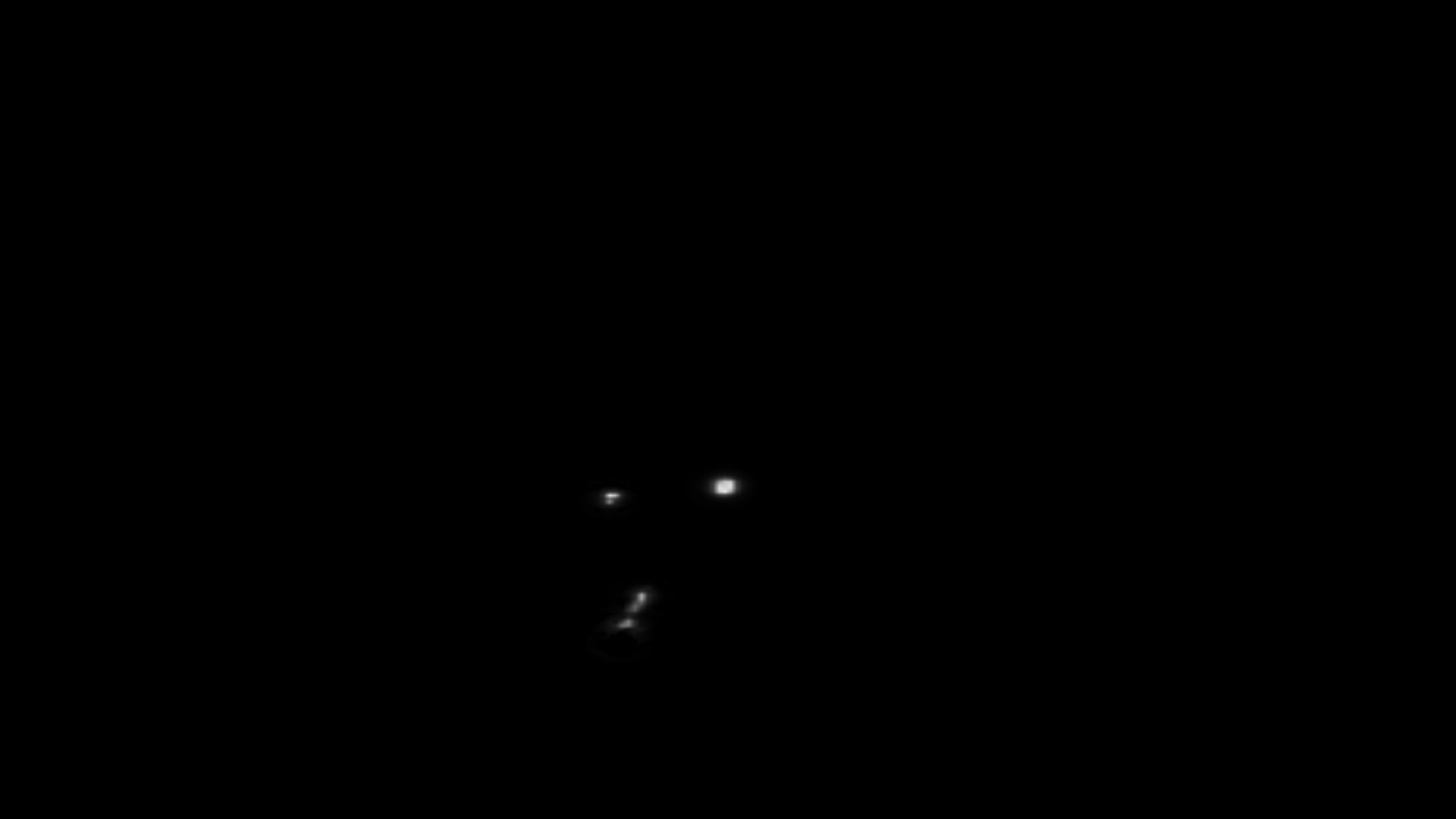
Interesting objects from the contour map
Traces from the contour map
It is worth noting that we sample only the .x channel from the contour map and take into account only the upper squares.
Traffic
To implement the movement of the tracks, almost the same trick is used as in the effect of intoxication. A unit-sized circle is added and we sample 8 times the outline map for interesting objects and traces, as well as the color texture.
Note that we only divided the found paths by 8.0.
Since we are in the space of texture coordinates [0-1] 2 , the presence of a circle of radius 1 to circle a single pixel will create unacceptable artifacts:
Therefore, before moving on, let's find out how this radius is calculated. To do this, we need to return to the missing lines 15-21. A minor problem with calculating this radius is that its calculation is scattered around the shader (possibly due to shader optimizations by the compiler). Therefore, here is the first part (15-21) and the second (41-42):
  15: add_sat r1.xy, -r0.xyxx, l(0.030000, 0.030000, 0.000000, 0.000000)
  16: add r1.x, r1.y, r1.x
  17: add_sat r0.xy, r0.xyxx, l(-0.970000, -0.970000, 0.000000, 0.000000)
  18: add r0.x, r0.x, r1.x
  19: add r0.x, r0.y, r0.x
  20: mul r0.x, r0.x, l(20.000000)
  21: min r0.x, r0.x, l(1.000000)
  ...
  41: add r0.x, -r0.x, l(1.000000)
  42: mul r0.xy, r0.xyxx, l(0.030000, 0.125000, 0.000000, 0.000000)
As you can see, we only consider texels from [0.00 - 0.03] next to each surface, summarize their values, multiply 20 and saturate. Here's what they look like after lines 15-21:

And here's how after line 41:

On line 42, we multiply this by 0.03, this value is the radius of the circle for the entire screen. As you can see, closer to the edges of the screen, the radius becomes smaller.
Now we can look at the assembler code responsible for the movement:
  40: mul r3.x, cb0[0].x, l(0.100000)
  41: add r0.x, -r0.x, l(1.000000)
  42: mul r0.xy, r0.xyxx, l(0.030000, 0.125000, 0.000000, 0.000000)
  43: mov r3.yzw, l(0, 0, 0, 0)
  44: mov r4.x, r0.y
  45: mov r4.y, r2.w
  46: mov r4.z, l(0)
  47: loop
  48:  ige r4.w, r4.z, l(8)
  49:  breakc_nz r4.w
  50:  itof r4.w, r4.z
  51:  mad r4.w, r4.w, l(0.785375), -r3.x
  52:  sincos r5.x, r6.x, r4.w
  53:  mov r6.y, r5.x
  54:  mul r5.xy, r0.xxxx, r6.xyxx
  55:  mad r5.zw, r5.xxxy, l(0.000000, 0.000000, 0.125000, 0.125000), r1.zzzw
  56:  mul r6.xy, r5.zwzz, l(0.500000, 0.500000, 0.000000, 0.000000)
  57:  sample_indexable(texture2d)(float,float,float,float) r4.w, r6.xyxx, t2.yzwx, s2
  58:  mad r4.x, r4.w, l(0.125000), r4.x
  59:  mad r5.zw, r5.zzzw, l(0.000000, 0.000000, 0.500000, 0.500000), l(0.000000, 0.000000, 0.500000, 0.000000)
  60:  sample_indexable(texture2d)(float,float,float,float) r4.w, r5.zwzz, t2.yzwx, s2
  61:  mad r4.y, r4.w, l(0.125000), r4.y
  62:  mad r5.xy, r5.xyxx, r1.xyxx, r1.zwzz
  63:  sample_indexable(texture2d)(float,float,float,float) r5.xyz, r5.xyxx, t0.xyzw, s0
  64:  mad r3.yzw, r5.xxyz, l(0.000000, 0.125000, 0.125000, 0.125000), r3.yyzw
  65:  iadd r4.z, r4.z, l(1)
  66: endloop
Let's stay here for a minute. On line 40 we get the time coefficient - just elapsedTime * 0.1 . In line 43 we have a buffer for the color texture obtained inside the loop.
r0.x (lines 41-42) is, as we now know, the radius of the circle. r4.x (line 44) is the outline of interesting objects, r4.y (line 45) is the outline of tracks (previously divided by 8!), and r4.z (line 46) is the loop counter.
As you might expect, the loop has 8 iterations. We start by calculating the angle in radians i * PI_4 , which gives us 2 * PI - a full circle. The angle is distorted over time.
Using sincos, we determine the sampling point (unit circle) and change the radius using multiplication (line 54).
After that, we go around the pixel in a circle and sample the contours and color. After the cycle, we get the average values (due to dividing by 8) of the contours and colors.
   float timeParam = time * 0.1;
   // adjust circle radius
   circle_radius = 1.0 - circle_radius;
   circle_radius *= 0.03;
   float3 color_circle_main = float3(0.0, 0.0, 0.0);
   [loop]
   for (int i=0; 8 > i; i++)
   {
      // full 2*PI = 360 angles cycle
      const float angleRadians = (float) i * PI_4 - timeParam;
      // unit circle
      float2 unitCircle;
      sincos(angleRadians, unitCircle.y, unitCircle.x); // unitCircle.x = cos, unitCircle.y = sin
      // adjust radius
      unitCircle *= circle_radius;
      // * base texcoords (circle) - note we also scale radius here by 8
      // * probably because of dimensions of outline map.
      // line 55
      float2 uv_outline_base = colorUV + unitCircle / 8.0;
      // * interesting objects (circle)
      float2 uv_outline_interesting_circle = uv_outline_base * 0.5;
      float outline_interesting_circle = texture2.Sample( sampler2, uv_outline_interesting_circle ).x;
      outlineInteresting += outline_interesting_circle / 8.0;
      // * traces (circle)
      float2 uv_outline_traces_circle = uv_outline_base * 0.5 + float2(0.5, 0.0);
      float outline_traces_circle = texture2.Sample( sampler2, uv_outline_traces_circle ).x;
      outlineTraces += outline_traces_circle / 8.0;
      // * sample color texture (zooming effect) with perturbation
      float2 uv_color_circle = colorUV + unitCircle * offsetUV;
      float3 color_circle = texture0.Sample( sampler0, uv_color_circle ).rgb;
      color_circle_main += color_circle / 8.0;
   }
Color sampling will be performed in much the same way, but we will add an offset multiplied by a “single” circle to the base colorUV .
Brightness
After the cycle, we sample the brightness map and change the final brightness values (because the brightness map does not know anything about the contours):
  67: sample_indexable(texture2d)(float,float,float,float) r0.xy, r1.zwzz, t3.xyzw, s0
  68: mad_sat r0.xy, -r0.xyxx, l(0.800000, 0.750000, 0.000000, 0.000000), r4.xyxx
HLSL Code:
   // * Sample intensity map
   float2 intensityMap = texture3.Sample( sampler0, colorUV ).xy;
   float intensityInteresting = intensityMap.r;
   float intensityTraces = intensityMap.g;
   // * Adjust outlines
   float mainOutlineInteresting = saturate( outlineInteresting - 0.8*intensityInteresting );
   float mainOutlineTraces = saturate( outlineTraces - 0.75*intensityTraces );
Gray corners and the final unification of everything
The gray color closer to the corners is calculated using the scalar product (assembler line 69):
   // * Greyish color
   float3 color_greyish = dot( color_circle_main, float3(0.3, 0.3, 0.3) ).xxx;
Then two interpolations follow. The first combines gray with the “color in the circle” using the first mask I described, so the corners become gray. In addition, there is a coefficient of 0.6, which reduces the saturation of the final image:
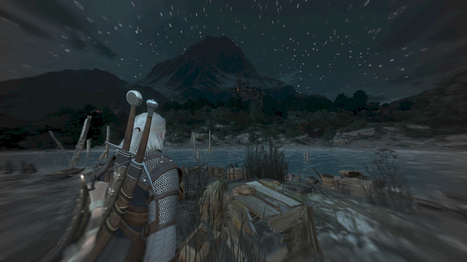
The second combines the first color with the above using fisheyeAmount . This means that the screen becomes gradually darker (due to multiplication by 0.6) and gray at the corners! Ingenious.
HLSL:
   // * Determine main color.
   // (1) At first, combine "circled" color with gray one.
   // Now we have have greyish corners here.
   float3 mainColor = lerp( color_greyish, color_circle_main, mask_gray_corners ) * 0.6;
   // (2) Then mix "regular" color with the above.
   // Please note this operation makes corners gradually gray (because fisheyeAmount rises from 0 to 1)
   // and gradually darker (because of 0.6 multiplier).
   mainColor = lerp( color, mainColor, fisheyeAmount );
Now we can move on to adding the contours of objects.
The colors (red and yellow) are taken from the constant buffer.
   // * Determine color of witcher senses
   float3 senses_traces = mainOutlineTraces * colorTraces;
   float3 senses_interesting = mainOutlineInteresting * colorInteresting;
   float3 senses_total = 1.2 * senses_traces + senses_interesting;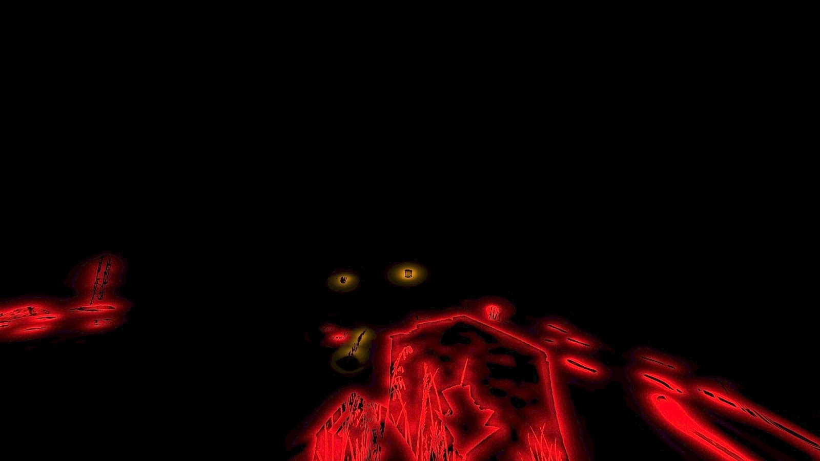
Fuh! We are almost at the finish line!
We have the final color, there is the color of the witch’s instinct ... it remains to somehow combine them!
And for this, simple addition is not suitable. First we compute the scalar product:
  78: dp3_sat r0.x, r0.xyzx, l(1.000000, 1.000000, 1.000000, 0.000000)
  float dot_senses_total = saturate( dot(senses_total, float3(1.0, 1.0, 1.0) ) );
which looks like this:

And these values at the very end are used to interpolate between color and the (saturated) witch's flair:
  76: mad r0.xyz, r0.yzwy, l(1.200000, 1.200000, 1.200000, 0.000000), r2.xyzx
  77: mov_sat r2.xyz, r0.xyzx
  78: dp3_sat r0.x, r0.xyzx, l(1.000000, 1.000000, 1.000000, 0.000000)
  79: add r0.yzw, -r1.xxyz, r2.xxyz
  80: mad o0.xyz, r0.xxxx, r0.yzwy, r1.xyzx
  81: mov o0.w, l(1.000000)
  82: ret
   float3 senses_total = 1.2 * senses_traces + senses_interesting;
   // * Final combining
   float3 senses_total_sat = saturate(senses_total);
   float dot_senses_total = saturate( dot(senses_total, float3(1.0, 1.0, 1.0) ) );
   float3 finalColor = lerp( mainColor, senses_total_sat, dot_senses_total );
   return float4( finalColor, 1.0 );
And that is all.
The full shader is available here .
Comparison of my (left) and original (right) shaders:
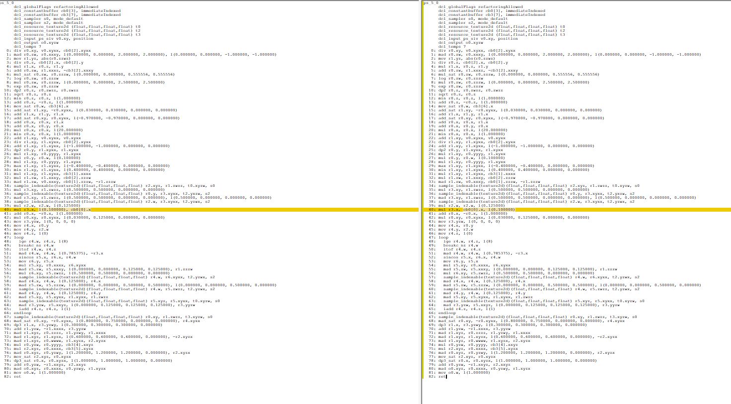
I hope you enjoyed this article! There are many brilliant ideas in the mechanics of the “witcher instinct”, and the finished result is very plausible.
[Previous parts of the analysis: first and second .]